
Chapter 3
Establishing Broad Functional Understanding
3.1 Introduction
In the previous chapter, we learned how to capture, in a concrete and actionable form, expectations stakeholders have for the system under consideration. These expectations are tied to higher-level business goals or mission objectives that define the purpose for which a system is being created. A system, however, exists within a context or operates within an external environment. Understanding a system’s operational aspects within its environment is also extremely important. It helps clearly delineate where a system’s boundary is, what elements in its external environment a system must interact with, and what those interactions are.
In military and government projects, the term concept of operations or ConOps is used to establish a broad operational understanding of the system in its environment. This broad understanding includes a system context, system use cases or operational scenarios, an end-to-end operational view of the system, and any design constraints along with a rationale for those constraints (American National Standards Institute/American Institute of Aeronautics and Astronautics [ANSI/AIAA], 2012; National Aeronautics and Space Administration [NASA], 2007). We discuss each of these elements in the sections that follow.
ConOps is an operational view of the system from the perspective of its users, and it gives a broad understanding of the capabilities a system must deliver to fulfill its mission objectives.
3.2 System Context
A system context shows the system as a black box along with all external entities (human and nonhuman) with which it must interact in its operational environment. Figure 3.1 shows a system context diagram for the building automation system we introduced in the previous chapter.
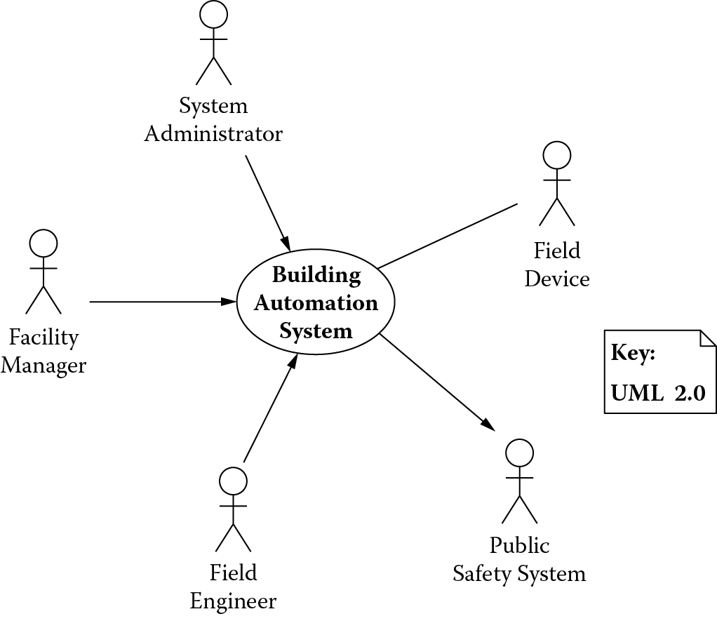
The diagram in Figure 3.1 shows the building automation system with all its actors, a term used in Unified Modeling Language (UML) to describe the external entities with which a system must interact. For the building automation system, these include field devices that report operating conditions of a building, a facility manager who monitors these conditions, a field engineer who deploys and maintains the field devices, a system administrator who administers the system and its users, and a public safety system that is notified under conditions that threaten the safety and security of residents in the building being monitored.
System context captures all external entities with which a system must interact in its operational environment.
3.3 System Use Cases
Functional capabilities or operational scenarios of a system can be represented with use cases based on how the external actors shown in the context diagram in Figure 3.1 intend to use the system. For instance, the field engineer intends to manage field devices and dynamically reconfigure them. The facilities manager intends to manage alarms generated by field devices that monitor a building. Alarms related to events that could cause loss of life also result in notifications to the public safety system. The system administrator intends to manage the users of the building automation system.
Some of the use cases related to the goals of the actors of the building automation system are shown in Figure 3.2. These use cases can be grouped by product features they realize (shown as notes on the right of Figure 3.2) and provide a broad functional context of the system under development.
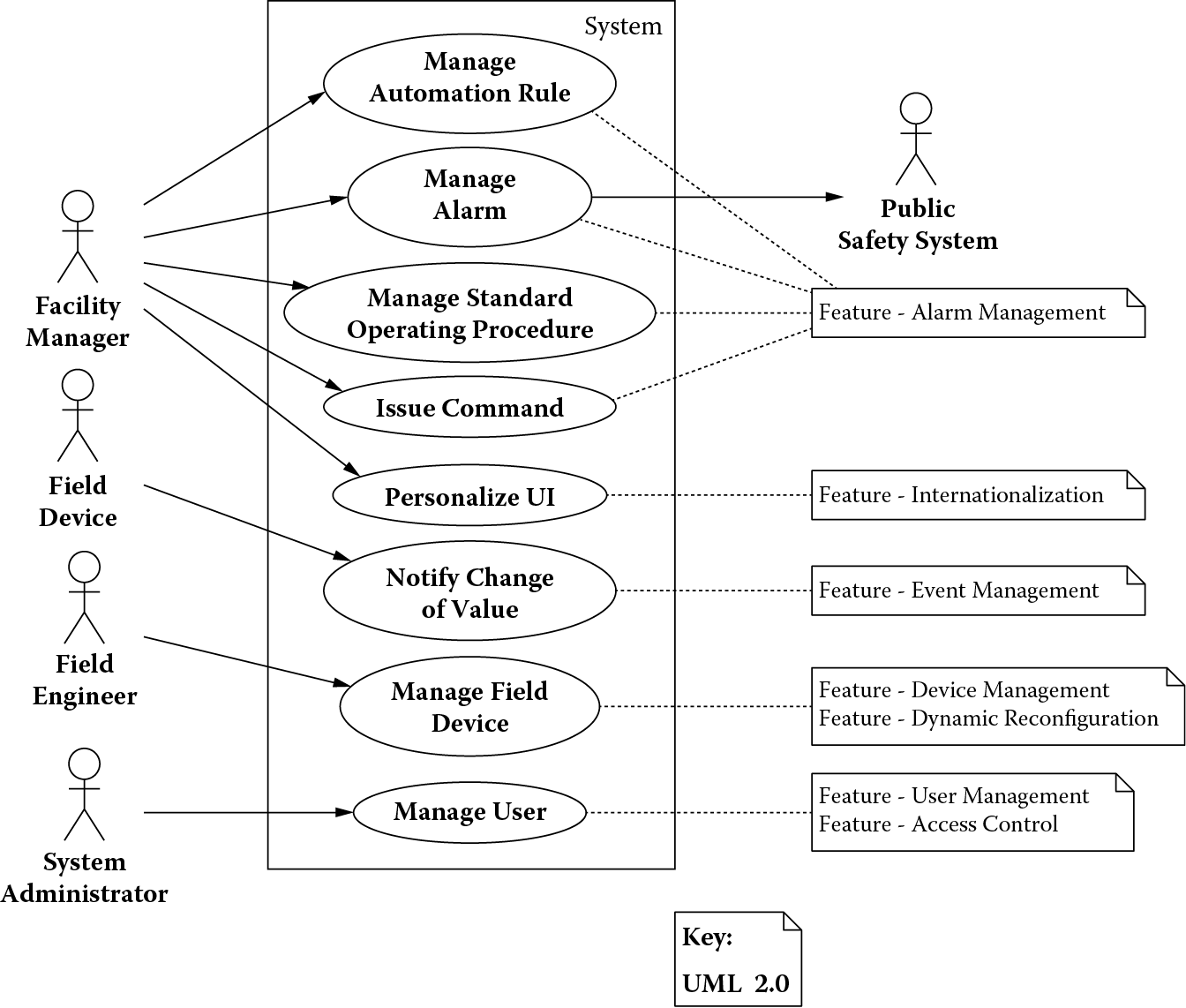
The use cases that implement the Alarm Management and Internationalization features are designed for the facilities manager. These include Manage Automation Rules for creating, updating, or deleting rules for automating building functions; Manage Alarm for responding to alarms generated by the system in response to a life-critical situation; Manage Standard Operating Procedures for creating, updating, or deleting standard operating procedures for handling policies related to monitoring the health of a building; Issue Command for commanding a field device (to reset itself, for example); and Personalize UI for customizing the user interface to a particular language and locale.
The Event Management feature includes a single use case, Notify Change of Value, used by a field device to notify change in any of its property values (temperature value change in a thermostat, for example). The features Field Device Management and Dynamic Reconfiguration are implemented through the use case Manage Field Device used by a field engineer. Finally, User Management and Access Control are provided through the use case Manage User used by a system administrator.
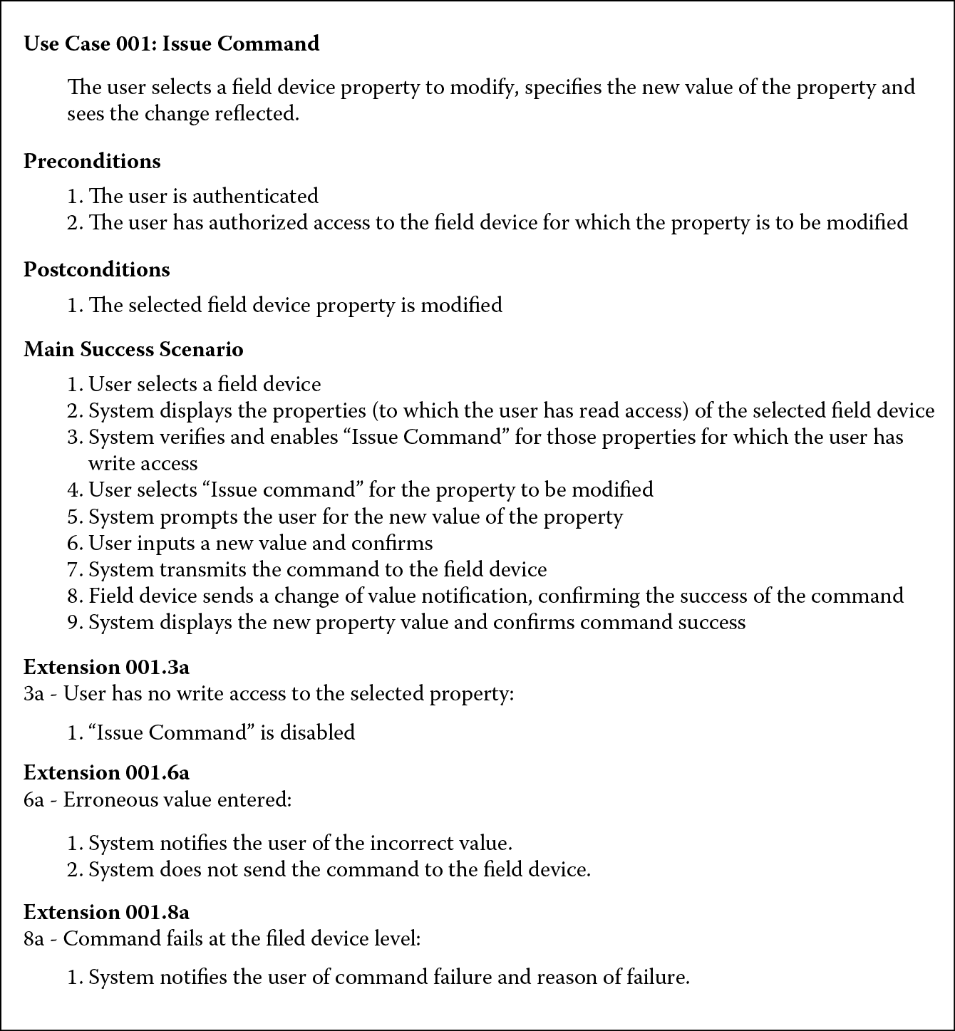
Although these are brief descriptions of the use cases, the elaboration of each use case can be fairly detailed (Larman, 2005). For illustration, the use case Issue Command is fully elaborated in Figure 3.3. The use case is given a unique identifier (Use Case 001) for cross-referencing. The elaboration consists of a brief description of the purpose of a use case followed by its preconditions, postconditions, the main success scenario, and extension points. Preconditions are things that must be true before the use case can be executed by the system; postconditions are things that must be true after the use case is executed by the system; a main success scenario consists of interactions between the user and the system that led to the desired outcome; and extension points are exceptions that might occur during the execution of the main success scenario. Extension points are numbered so it is clear which step of the given use case’s main success scenario caused the exception. For instance, Extension 001.6a is an exception that occurred at step 6 of the main success scenario for Use Case 001. If other exceptions were to occur at the same step, they would be labeled Extension 001.6b, Extension 001.6c, and so on.
The elaborated use cases can be used to determine the responsibilities (see responsibility-driven design by Wirfs-Brock and McKean, 2003) or operational capabilities of a given system. For instance, the following operational capabilities for the building automation system can be derived from the use cases shown in Figure 3.2:
- Send user commands to a field device
- Receive events from a field device
- Perform semantic translation for field device data
- Configure a field device
- Route data to a field device
- Evaluate and execute automation rules
- Send automation commands
- Generate alarm notifications
- Display device data
- Capture/relay user commands
- Display alarm notifications
- Edit/create automation rules
- Retrieve data from a field device
- Store field device configuration
- Propagate change-of-value notifications
- Authenticate and authorize users
- Persist automation rules, user preferences, alarms
Use cases are interactions initiated by users or external systems (referred to as actors). Use cases are goal oriented; in other words, at the end of a use case the actor initiating the given use case walks away from the system with something of value. They can be used for determining operational capabilities a system must support.
3.4 Domain Model
The descriptions of use cases introduce some significant concepts from the building automation domain, such as field device, field device properties, rules, alarms, and standard operating procedures. These concepts are significant because they represent the information/entities that are created, destroyed, associated, and used in various ways within a use case to achieve something of value. A conceptual or domain model is used to capture these significant terms and the relationships among them (Larman, 2005). Figure 3.4 shows this model for the building automation system using a UML class diagram. The convention of reading relationships shown in the diagram is top to bottom and left to right.
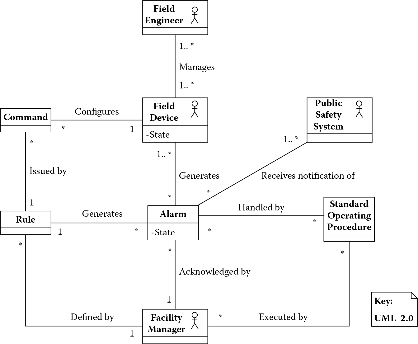
The domain model establishes a standard vocabulary of concepts that can be used when elaborating use cases and provides a succinct description from the problem domain. When examining the model in Figure 3.4, one can describe the building automation domain with relative ease. A field engineer manages field devices that monitor the internal operations of a building. The field devices can generate alarms under conditions that create a safety hazard. The alarms are monitored by facility managers, who follow standard operating procedures when handling these alarms. Facility managers can also define rules that can automatically evaluate hazardous conditions and generate alarms or can automatically issue commands to field devices to take certain actions.
Such a succinct description not only can be a great aid in establishing shared understanding of the problem domain but also can vastly improve the quality of system requirements because the standard vocabulary introduces a level of consistency, making requirements less subject to different interpretations. There are some additional applications of a domain model that are discussed in further chapters.
A domain model can be used to capture significant concepts and their relationships, creating a shared understanding of a problem domain, and can be used to establish a standard vocabulary that can be used to elaborate use cases consistently.
3.5 An End-to-End Operational View
The overall goal of the building automation system is to monitor the locations within the buildings (using field devices) for normal building operations. These devices periodically report back the conditions, and the facility managers can monitor these conditions on their workstations. Conditions that may threaten the safety and security of the building residents are raised as alarms so that prompt action can be taken. Figure 3.5 shows this end-to-end operational view of the system.
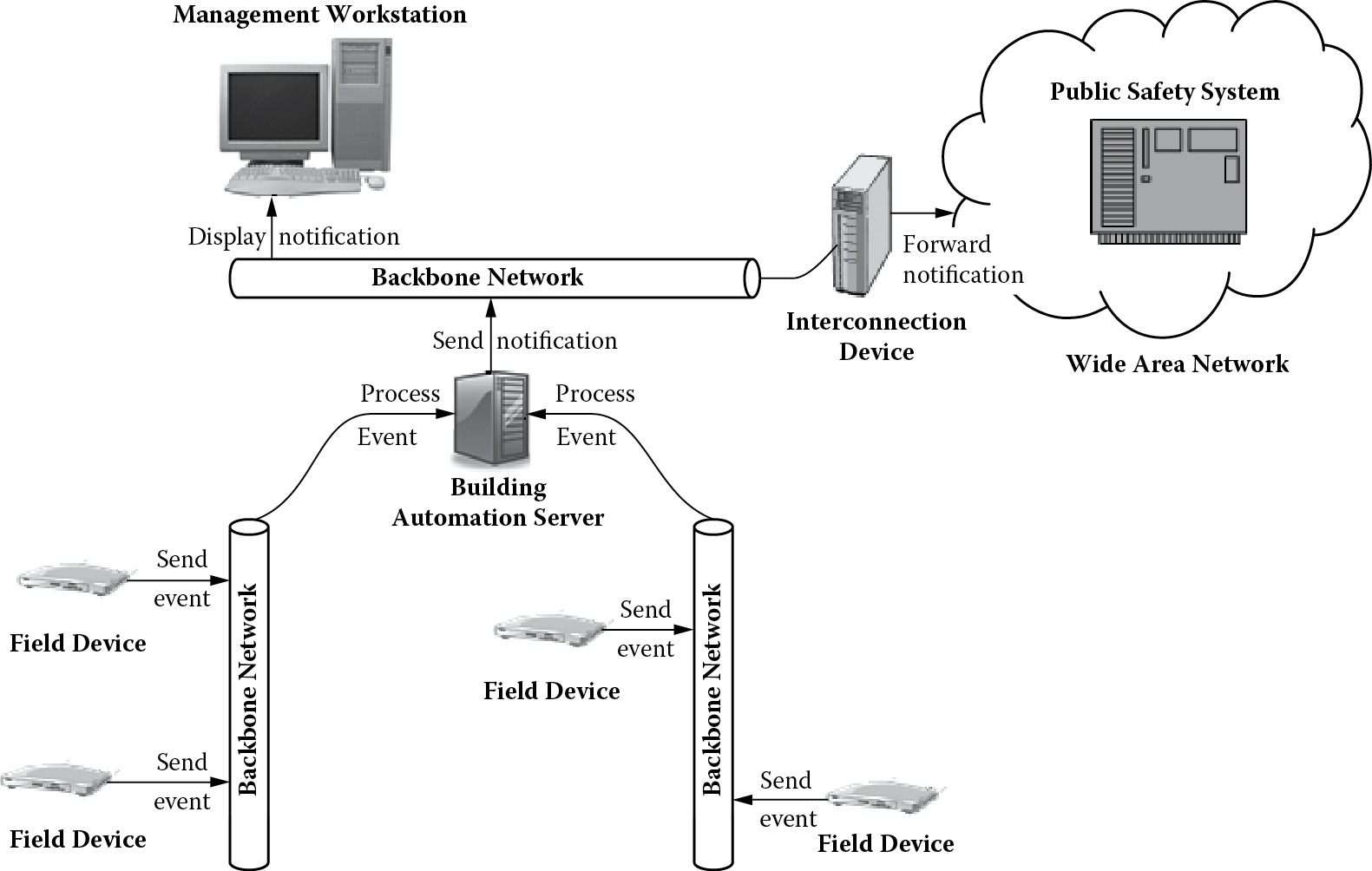
An end-to-end operational view provides a good conceptual understanding of the capabilities of a system. One can formulate an idea of what the system can do if it were available today. Operational scenarios or timelines based on this view can further provide details on time-sequenced order of major events the system must handle (NASA, 2007). Figure 3.6 shows one such operational scenario in which many field devices concurrently transmit events to the building automation system. The building automation system can process these events (and possibly request more data from the devices) to determine if there is a safety hazard, in which case an alarm is generated. The alarm needs to be displayed on a facility manager’s workstation, and a notification also needs to be sent to the public safety system.
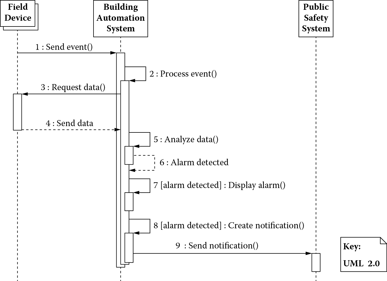
Such end-to-end operational scenarios can be useful in determining system configurations and operational activities necessary to achieve the engineering objectives. For instance, the execution snapshot in Figure 3.6 can be used as a basis for creating an initial performance model to obtain an estimate of the processing requirements of the building automation system to handle event volumes, event arrival rates, and timely dissemination of alarm notifications related to safety-critical situations.
Recall that one of the engineering objectives was that, in the event that data from the field devices begin to indicate the possibility of an alarm, the facilities managers and possibly the public safety system need to know about this possibility within 3 s of its occurrence. Under normal operating conditions, a single field device can generate 1 event/second in the worst case.
Table 3.1 specifies the computing requirements for each of these processing steps for a single event received from a field device. Work units represent central processing unit (CPU) consumption, the range being 1 to 5 with 1 representing CPU consumption for a simple task and 5 representing CPU consumption for a complex task. Network messages represent outbound messages from a processing step.
Computing Requirements
|
Processing Step |
Work Unit |
Network Message |
|
Send event (field device) |
0 |
1 |
|
Process event (building automation system) |
5 |
4 |
A sending event step does not require any processing (hence, a work unit value of 0) but merely transmission of data via a single network message from the field device to the building automation system. However, the process event step can be quite involved. First, the building automation system has to do semantic translation of event data received from a field device and evaluate it using a rule. The data may indicate an alarm condition and require additional data requests from other devices. For example, an event from a fire alarm may prompt a request for data from smoke detectors and sprinkler systems. We assume, in the worst case, an alarm condition leads to requests for data from two additional field devices (therefore, two data request messages to the devices). Finally, all the aggregated data need to be analyzed, possibly running several rules to determine if a situation is safety critical. So, a process event is a rather complex task; therefore, it is assigned a work unit value of 5. The total number of network messages is 4, assuming 2 messages for additional field devices mentioned previously and 1 message each to the facility manager workstation and the public safety system.
Table 3.2 shows the computing resources with their service times and the associated processing overhead. In the left section of the table, the names of computing devices in a typical server are in the leftmost column, the units of service provided by these devices in the second column, and the service time for each unit of service in the third column. For example, a CPU executes 1,000 instructions in 10 μs on a typical server that has a single CPU. The values in the right section of the table define processing overhead associated with the computing needs (work units and network messages) of the building automation system. For example, reading down the left processing overhead column, a single work unit results in the execution of 20,000 (20K) CPU instructions, no disk inputs/outputs (I/Os) or network messages. Reading down the right processing overhead column, a network message requires 10K CPU instructions, two physical I/Os, and transmission of one network message.
Computer Resources and Processing Overhead
|
Computer Resources |
Processing Overhead |
|||
|
Device |
Unit of Service |
Service Time/Unit of Service |
Work Unit |
Network Message |
|
CPU |
Thousand instructions |
0.00001 s |
20 |
10 |
|
Disk |
Physical I/O |
0.02 s |
0 |
2 |
|
Network |
Message |
0.01 s |
0 |
1 |
Table 3.1 and Table 3.2 can be used for calculating total computer resource requirements for our operational scenario. We show this in Table 3.3.
Total Computer Resource Requirements for Alarm Detection
|
Processing Step |
CPU Instructions (K) |
Physical I/O |
Network Messages |
|
Send event |
10 |
2 |
1 |
|
Process event |
140 |
8 |
4 |
|
Total |
150 |
10 |
5 |
The best-case elapsed time for the alarm detection scenario, therefore, is (150 × 0.00001) + (10 × 0.02) + (5 × 0.01) = 0.15150 s, which is well within our 3-s latency constraint for an alarm. This, however, is a ballpark estimate and does not take into account any network latency, unavailability, and queuing delays. We can continue to refine this model and its associated estimate as the design of the system matures and there is a better understanding of the event arrival rates and the topology of the system.
We can also try to gain a ballpark understanding of how we can handle the system load. Assume the building automation system is deployed on a 128-processor high-end server. The throughput of the server will be (128/0.15150) = approximately 845 events per second. To attain job flow balance, however, the system will have to be fast enough to handle the alarm events; thus, the throughput must be equal to the arrival rate of these events. Suppose the largest customer for the building automation system has 500,000 field devices on the premises. Assuming only 10% of these field devices are related to the safety-critical aspect of the building automation system (e.g., fire alarms, intrusion, etc.), we would need a cluster of (50,000/845) = approximately 60 servers just to handle the load created by these devices.
Although this is a ballpark analysis, such analysis can be valuable in understanding the flexibility that needs to be designed into the system such that it can be configured for handling the latency and throughput needs of its operational scenario. In case of the given scenario, the system would have to be designed with flexibility such that it can be deployed on a single low-end server for a smaller customer or on a cluster of high-end servers for a larger customer. Essentially, it should scale gracefully to accommodate varying degrees of load it needs to handle.
3.6 Constraints
There are additional stakeholder concerns that have to be considered as they may constrain how a system is designed. For instance, it may be the case that the system under consideration has to be developed using a certain technology suite, such as the Microsoft platform and the Oracle DBMS. This a priori choice of technology will limit the ability of an architect to make design decisions, such as how the system is partitioned into tiers, the communication mechanisms across these tiers, and the strategies for security, fault, and transaction management. Table 3.4 enumerates a few such factors for the building automation system.
Constraints for Designing the Building Automation System
|
Category |
Factor |
Description |
|
Organization |
Expertise |
The development organization has a strong background in development on the Microsoft platform. |
|
Technology |
Cost |
The system must reuse the company’s existing rules engine. |
|
Product |
Variability |
The system must handle a wide range of disparate field devices and configurations, ranging from 500 to 500,000 such devices at customer sites. |
These factors have been broadly categorized into those that result from the capabilities or limitations of an organization to work with a particular technology suite or type of system, a mandate that the project use a particular technology to promote strategic reuse or contain cost, and the characteristics of the product, such as the types of customers it needs to serve or the regulatory concerns it must address.
Constraints are decisions that have been made to limit the freedom an architect has with respect to those decisions, therefore constraining how the system must be designed.
3.7 Summary
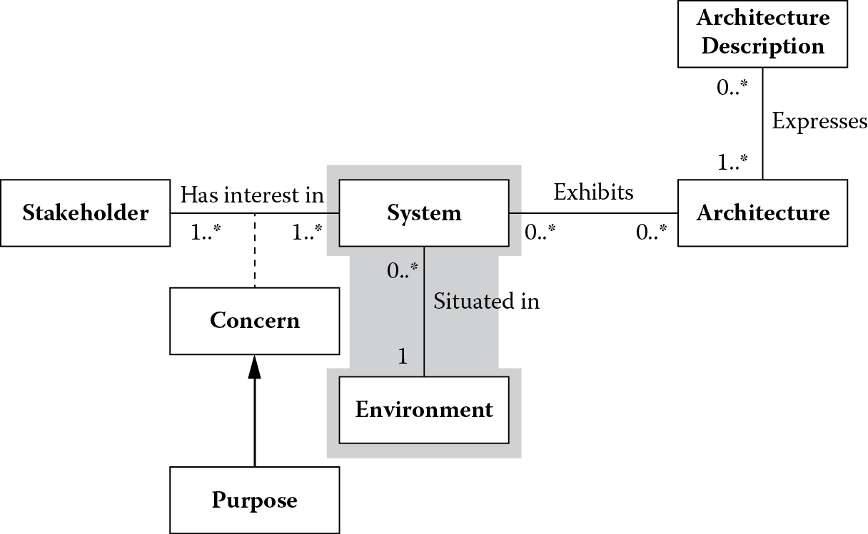
This chapter explored the shaded portion of ISO/IEC 42010 conceptual framework for system and software architecture shown in Figure 3.7.
ConOps can be used to understand the operational environment of a system under design. ConOps establish this operational understanding through the use of system context, system use cases or operational scenarios, domain model, an end-to-end operational view of the system, and design constraints. System context captures all external entities or actors a system must interact with in its operational environment. The intent of how these actors want to use the system becomes the basis for defining use cases and, finally, the responsibilities the system must fulfill. The use cases and responsibilities are expressed using a standard vocabulary established through the model of the problem domain. An end-to-end operational view of the system uses use case scenarios to capture a time-ordered sequence of major events a system must handle. This helps understand system configurations and operational activities necessary for achieving the capabilities a system must have. Constraints can limit the freedom of an architect in how the system must be designed to achieve these operational capabilities.
3.8 Questions
- Pick one use case from Figure 3.2 and elaborate using the format shown in Figure 3.3. Make sure you express the use case using the vocabulary of the problem domain as established in Figure 3.4.
- From the use case elaborated in problem 1, identify key operational capabilities that must be assigned to the building automation system.
- During elaboration of the use case, were there any significant terms or concepts that you found were not represented in the domain model shown in the chapter? If so, augment the domain model by adding these concepts.
- Consider an end-to-end scenario in which a user wants to change a property value (such as the temperature setting of a thermostat) of a device. Using the technique described in Section 3.5, model and estimate the elapsed time between the moment the user issues the command and the moment when the property value change takes effect.
References
American National Standards Institute/American Institute of Aeronautics and Astronautics (ANSI/AIAA), ANSI/AIAA G-043A-2012 Guide for the Preparation of Operational Concept Documents. Reston, VA: AIAA, 2012.
C. Larman, Applying UML and Patterns, third edition. Upper Saddle River, NJ: Prentice-Hall, 2005.
National Aeronautics and Space Administration (NASA), Systems Engineering Handbook (NASA/SP-2007-6105 Rev1). Washington, DC: NASA Headquarters, December 2007.
R. Wirfs-Brock and A. McKean, Object Design: Roles, Responsibilities, and Collaborations. Boston: Addison-Wesley, 2003.