
2.5. SM Display with Multi-zone Disks
Over the past few years, magnetic recording areal density has increased at the rate of 60% per year from increases in both bits per inch (bpi) and tracks per inch (tpi) [121], [82], [33]. Bits per inch (called linear density) shows how many bits can be stored on a track, i.e., the number of sectors on a track. To meet the demands for a higher storage capacity, disk drive manufacturers have invariably introduced disks with zones. A zone is a contiguous collection of disk cylinders whose tracks have the same storage capacity, i.e., the number of sectors per track is constant in the same zone (ZBR technique). Tracks are longer towards the outer portions of a disk platter as compared to the inner portions, hence, more data can be recorded in the outer tracks. This is because that the linear density should be maintained near the maximum that the disk drive can support. Thus the amount of data stored on each track should scale with its length.
While ZBR increases the storage capacity of the disk, it produces a disk that does not have a single data transfer rate. The multiple transfer rates are due to: 1) the variable storage capacity of the tracks, and 2) a fixed number of revolutions per second for the platters. Assuming m zones in a disk drive, we denote ith zone from the outermost zone as Zi, i.e., Z0 is the outermost zone and Zm–1 is the innermost one. We also denote the data transfer rate of zone Zi as R(Zi). Then, R(Zi) ≥ R(Zj) for all i, j where j > i and 0 ≤ i, j < m. For example, Figure 2.12 shows a disk drive with four zones. The outermost zone, z0, has four tracks of the size of four sectors. The innermost zone, Z3, has two tracks with the track size of one sector.
Figure 2.12. An example of zone configuration.

In this section, we discuss alternative designs to support a continuous display of SM objects using a single disk with m zones: Z0, Z1, …, Zm–1. The transfer rate of zone i is denoted as R(Zi). Z0 denotes the outermost zone with the highest transfer rate: R(Z0) ≥ R(Z1) ≥ … ≥ R(Zm–1). We will extend these techniques to a multi-disk architecture in Section 5.3. To describe these techniques, we first make a number of simplifying assumptions. Subsequently, we will relax these assumptions one by one. These assumptions are as follows:
A constant bit rate. That is, the display bandwidth RC of a single object is fixed for the entire display duration of the object. This will be relaxed in Section 2.5.3.
The display bandwidth is less than or equal to the average transfer rate of the disk,

2.5.1. Track Pairing (TP)
A straightforward way to model a multi-zone disk drive is to construct logical tracks that have the same size and identical data transfer rate regardless of the location of data in a multi-zone disk drive. Assuming a single disk drive with #TR physical tracks, track pairing (TP) [15] constructs a logical track by pairing two physical tracks such as pairing the outermost track (PT0) with the innermost track (PT#TR-1), working itself toward the center of the disk platter. The result is a logical disk drive that consists of ![]() logical tracks that have the same storage capacity. Thus, a logical track LTi consists of two physical tracks, PTi and PT#TR-i-1, where
logical tracks that have the same storage capacity. Thus, a logical track LTi consists of two physical tracks, PTi and PT#TR-i-1, where ![]() . Figure 2.13 shows the mapping between physical tracks and logical tracks in TP.
. Figure 2.13 shows the mapping between physical tracks and logical tracks in TP.
Figure 2.13. Track pairing (TP).

We can guarantee the same storage capacity of logical tracks with the assumption that the storage capacity of physical tracks increases linearly from the innermost track to the outermost track. However, in real multi-zone disk drives, there is no such linear increase in the storage capacity of tracks. Assuming m zones, there are only m different sizes of physical tracks because the storage capacity of tracks in the same zone is identical. To enforce the identical storage capacity of logical tracks in TP, the system limits the storage capacity of logical tracks by the smallest one among all logical tracks. Therefore, the fragmented data in a logical track is wasted. For example, Seagate Cheetah 4LP disk drive (see Table 2.1) with 4 GByte storage capacity consists of 56,782 physical tracks. We can construct 28,391 logical tracks by TP. The storage capacity of the smallest logical track is 0.146 MByte and the largest one is 0.158 MByte. Thus, the storage capacity of a logical track is determined as 0.146 MByte (sizeof(£T) = 0.146 MByte) and 181 MByte (4.2%) of disk space is wasted in this disk.
Using this logical single-zone disk drive, one can apply Simple in support of hiccup-free display. A block consists of one or multiple logical tracks:
Equation 2.17
![]()
Eq. 2.5 can be modified to support NTP simultaneous displays with TP.
Equation 2.18
![]()
where rot is one revolution time required to read a physical track. For example, one revolution time is 8.33 msec for a disk drive with the rotation speed of 7,200 revolutions per minute. Note that only one intra-block seek is considered even though a block consists of multiple logical tracks. This is because we can eliminate unnecessary seeks by constructing a block with adjacent logical tracks [12]. Thus, for a given block size, the maximum throughput is:
[12] A disk drive minimizes inter-track seek time with track skewing and read-ahead buffer techniques when it reads adjacent tracks [139].
Equation 2.19
![]()
Then, the cost per stream and the maximum startup latency are:
Equation 2.20
![]()
Equation 2.21
![]()
TP may suffer from a long intra-block seek time because a block consists of at least two separate physical tracks. For example, in order to retrieve Y1 in Figure 2.14, the system performs the maximum intra-block seek because it retrieves the outermost track and the innermost track. Combined with the maximum inter-block seek time assumed in Simple, the portion of wasteful work might be significant. Applying SCAN to TP (TP_SCAN) prevents this limitation because one block retrieval can be separated in two track retrievals and their retrieval order can be shuffled to minimize seek time among track retrievals. To determine the maximum throughput with TP_SCAN, the following equation should be satisfied:
Equation 2.22

Figure 2.14. Continuous display with TP.

The cost per stream and the maximum startup latency with TP_SCAN are:
Equation 2.23
![]()
Equation 2.24
![]()
2.5.2. Logical Track (LT)
LT [85] is an alternative approach to construct equi-sized logical tracks from various-sized physical tracks of a multi-zone disk drive. LT constructs a logical track with a set of physical tracks, each from a distinct zone provided by a disk drive. Thus, assuming m zones in a disk, a logical track consists of a set[13] of physical tracks:
[13] We use the set notation, { : }, to refer to a collection of tracks from different zones of several disk drives. This notation specifies a variable before the colon and the properties that each instance of the variable must satisfy after the colon.
Equation 2.25
![]()
where PTi(Zj) denotes ith physical track in zone Zj of the disk. The value of i is bounded by the zone with the fewest physical tracks, i.e., 0 ≤ i < Min[NT(Zj)], where NT(Zj) is the number of physical tracks in the zone j of the disk dive. Figure 2.15 shows the mapping between physical tracks and logical tracks in LT.
Figure 2.15. LT for a single disk drive.

Ideally, if there are the same number of tracks in all zones, there would be no wasted disk space with LT. However, different zones consist of different number of physical tracks (see Table 2.1). In order to enforce the same storage capacity of a logical track, LT wastes disk space because the zone with the fewest physical tracks determines the total number of logical tracks in a disk. In particular, this technique eliminates the physical tracks of those zones that have more than NTmin = Min[NT(Zj)], i.e., PTk(Zj) with NTmin ≤ k< NT(Zj), 0 ≤ j < m, are eliminated. For example, Seagate Cheetah 4LP disk drive (see Table 2.1) with 4 GByte storage capacity consists of 7 zones. The innermost zone has the smallest number of physical tracks, 5421, while the outermost zone has 11617. Thus, 6196 tracks in zone 0 must be eliminated. LT wastes 1.5 GByte (35%) of disk space with this disk model. Note that the amount of waste disk space with LT depends on the physical zone characteristics of a disk drive. However, in general, LT wastes far more disk space than TP.
Similar to TP, LT provides equi-sized logical tracks with a single data transfer rate such that one can apply the continuous display techniques such as Simple and SCAN. A block consists of one or multiple logical tracks:
Equation 2.26
![]()
Eq. 2.5 can be modified to support NLT simultaneous displays with LT.
Equation 2.27
![]()
where rot is one revolution time required to read a single physical track. Thus, for a given block size, the maximum throughput is;
Equation 2.28

Then, the maximum startup latency is:
Equation 2.29
![]()
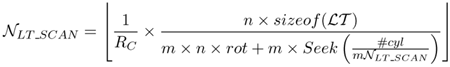
The increased number (m) of intra-block seeks may result in a poor performance. Applying SCAN to LT (LT_SCAN) reduces seek times as in TP _SCAN. The maximum throughput with LT _SCAN is;
Equation 2.30
The maximum startup latency with LT_SCAN is;
Equation 2.31
![]()
2.5.3. FIXB and VARB
We start by describing the two techniques based only on constrained data placement. The two proposed techniques partition each object X into / blocks: X0, X1, X2,…, Xf_1. The first, termed FIXB, renders the blocks equi-sized. With the second technique, termed VARB, the size of a block depends on the transfer rate of its assigned zone. The advantage of FIXB is its ease of implementation. There are two reasons for this claim. First, a fixed block size simplifies the implementation of a file system that serves as the interface between memory and magnetic disk drive. Second, the design and implementation of a memory manager with fixed frames (the size of a frame corresponds to the size of a block) is simpler than one with variable sized frames. This is particularly true in the presence of multiple displays that result in race conditions when competing for the available memory[14]. While VARB might be more complicated to implement, it requires a lower amount of memory and incurs a lower latency as compared to FIXB when the bandwidth of the disk drive is a scarce resource. FIXB and VARB share many common characteristics. In Section 2.5.3, we describe FIXB. Subsequently, Section 2.5.3 describes VARB and its differences as compared to FIXB. In Sec. 2.5.3, we extend both techniques to employ disk scheduling for further minimization of seek time.
[14] We have participated in the design, coding, and debugging of a multi-user buffer pool manager with a fixed block size for a relational storage manager. We explored the possibility of extending this buffer pool manager to support variable block size, and concluded that it required significant modifications.
Fixed Block Size, FIXB
With this technique, the blocks of an object X are rendered equi-sized. Let B denote the size of a block. The system assigns the blocks of X to the zones in a round-robin manner starting with an arbitrary zone. FIXB configures the system to support a fixed number of simultaneous displays, N. This is achieved by requiring the system to scan the disk in one direction, say starting with the outermost zone moving inward, visiting one zone at a time and multiplexing the bandwidth of that zone among N block reads. Once the disk arm reads N blocks from the innermost zone, it is repositioned to the outermost zone to start another sweep of the zones. The time to perform one such a sweep is denoted as TScan. The system is configured to produce and display an identical amount of data per TScan period. The time required to read N blocks from zone i, denoted TMUX(Zi), is dependent on the transfer rate of zone i. This is because the time to read a block (Tdisk(Zi)) during one TMUX(Zi) is a function of the transfer rate of a zone.
Figure 2.16 shows TScan and its relationship with TMUX(Zi) for m zones. During each TMUx period, N active displays might reference different objects. This would force the disk to incur a seek when switching from the reading of one block to another, termed[15] Tw _seek(Zi). The computation of TW_seek(Zi) depends on the disk scheduling technique employed and hence discussed in Sec. 2.5.3. At the end of a TScan period, the system observes a long seek time (Tcseek) attributed to the disk repositioning its arm to the outermost zone. The disk produces m blocks of X during one TScan period (m × B bytes). The number of bytes required to guarantee a hiccup-free display of X during TScan should either be lower than or equal to the number of bytes produced by the disk. This constraint is formally stated as:
[15] Tw_seek(Zi) also includes the maximum rotational latency time.
Equation 2.32


The amount of memory required to support a display is minimized when the left hand side of Eq. 2.32 equals its right hand side.
During a TMUx, N blocks are retrieved from a single zone, ZActive. In the next TMUx period, the system references the next zone Z(Active+1)
mod m. When a display references object X, the system computes the zone containing Xo, say Zi. The transfer of data on behalf of X does not start until the active zone reaches Zi. One block of X is transferred into memory per TMUx. Thus, the retrieval of X requires f such periods. (The display of X may exceed ![]() seconds as described below.) The memory requirement for displaying object X varies due to the variable transfer rate. This is best illustrated using an example. Assume that the blocks of X are assigned to the zones starting with the outermost zone, Z0. If Z Active is z0 then this request employs one of the idle Tdisk(Z0) slots to read Xo. Moreover, its display can start immediately because the outermost zone has the highest transfer rate. The block size and N are chosen such that the data accumulates in memory when accessing outermost zones and decreases when reading data from innermost zones on behalf of a display (see Figure 2.17). In essence, the system uses buffers to compensate for the low transfer rates of innermost zones using the high transfer rates of outermost zones, harnessing the average transfer rate of the disk. Note that the amount of required memory reduces to zero at the end of one Tscan in preparation for another sweep of the zones.
seconds as described below.) The memory requirement for displaying object X varies due to the variable transfer rate. This is best illustrated using an example. Assume that the blocks of X are assigned to the zones starting with the outermost zone, Z0. If Z Active is z0 then this request employs one of the idle Tdisk(Z0) slots to read Xo. Moreover, its display can start immediately because the outermost zone has the highest transfer rate. The block size and N are chosen such that the data accumulates in memory when accessing outermost zones and decreases when reading data from innermost zones on behalf of a display (see Figure 2.17). In essence, the system uses buffers to compensate for the low transfer rates of innermost zones using the high transfer rates of outermost zones, harnessing the average transfer rate of the disk. Note that the amount of required memory reduces to zero at the end of one Tscan in preparation for another sweep of the zones.
Figure 2.17. Memory required on behalf of a display.

The display of an object may not start upon the retrieval of its block from the disk drive. This is because the assignment of the first block of an object may start with an arbitrary zone while the transfer and display of data is synchronized relative to the outermost zone, z0. In particular, if the assignment of Xo starts with a zone other than the outermost zone (say Zi, i ≠ 0) then its display might be delayed to avoid hiccups. The duration of this delay depends on: 1) the time elapsed from retrieval of Xo to the time that block Xm–i is retrieved from zone z0, termed TaccessZ0, and 2) the amount of data retrieved during TaccessZ0. If the display time of data corresponding to item 2 (Tdisplay(m–i)) is lower than TaccessZ0, then the display must be delayed by TaccessZ0 – Tdisplay(m_i). To illustrate, assume that Xo is assigned to the innermost zone Zm–1 (i.e., i = m – 1) and the display time of each of its block is 4.5 seconds, i.e., Tdisplay(1) = 4.5 seconds. If 10 seconds elapse from the time X0 is read until X1 is read from Zo then the display of X must be delayed by 5.5 seconds relative to its retrieval from Zm–1. If its display is initiated upon retrieval, it may suffer from a 5.5 second hiccup. This delay to avoid a hiccup is shorter than the duration of a Tscan. Indeed, the maximum latency observed by a request is Tscan when the number of active displays is less than [16] N:
[16] When the number of active displays exceeds N then this discussion must be extended with appropriate queuing models.
Equation 2.33

This is because at most N – 1 displays might be active when a new request arrives referencing object X. In the worst case scenario, these requests might be retrieving data from the zone that contains X0 (say Zi) and the new request arrives too late to employ the available idle slot. (Note that the display may not employ the idle slot in the next TMUX because Zi+1 is now active and it contains X1 instead of X0.) Thus, the display of X must wait one Tscan period until Zi becomes active again.
One can solve for the block size by observing from Figure 2.16 that TMUX(Zi) can be defined as:
Equation 2.34
![]()
Substituting this into Eq. 2.32, the block size is defined as:
Equation 2.35

Observe that FIXB wastes disk space when the storage capacity of the zones is different. This is because once the storage capacity of the smallest zone is exhausted then no additional objects can be stored as they would violate a round-robin assignment[17].
[17] Unless the number of blocks for an object is less than m. We ignored this case from consideration because video objects are typically very large.
Variable Block Size, VARB
VARB is similar to FIXB except that it renders the duration of TMUX(Zi) independent of the zone's transfer rate. This is achieved by introducing variable block size where the size of a block, B(Zi), is a function of the transfer rate of a zone. This causes the transfer time of each block, Tdisk to be identical for all zones (i.e., ![]() ). Similar to FIXB, the blocks of an object are assigned to the zones in a round-robin manner and the concept of TScan is preserved. This means that the blocks of an object X are no longer equi-sized. The size of a block X depends on the zone it is assigned to. However, the change in block size requires a slight modification to the constraint that ensures a continuous display:
). Similar to FIXB, the blocks of an object are assigned to the zones in a round-robin manner and the concept of TScan is preserved. This means that the blocks of an object X are no longer equi-sized. The size of a block X depends on the zone it is assigned to. However, the change in block size requires a slight modification to the constraint that ensures a continuous display:
Equation 2.36

The duration of TMUX(Zi) is now independent of the transfer rate of a zone but still is a function of Zi due to the incurred seek time (see Sec. 2.5.3). TMUX(Zi) is now defined as:
Equation 2.37
![]()
Substituting this into Eq. 2.36, the size of a block for a zone Zi is defined as:
Equation 2.38

Similar to FIXB, VARB employs memory to compensate for the low bandwidth of innermost zones using the high bandwidth of the outermost zones. This is achieved by reading more data from the outermost zones. Moreover, the display of an object X is synchronized relative to the retrieval of its block from the outermost zone and may not start immediately upon retrieval of X0. VARB wastes disk space when ![]() , and 0 ≤ (i, j) < m. The amount of wasted space depends on the zone that accommodates the fewest blocks. This is because the blocks of an object are assigned to the zones in a round-robin manner and once the capacity of this zone is exhausted the storage capacity of other zones cannot be used by other video objects.
, and 0 ≤ (i, j) < m. The amount of wasted space depends on the zone that accommodates the fewest blocks. This is because the blocks of an object are assigned to the zones in a round-robin manner and once the capacity of this zone is exhausted the storage capacity of other zones cannot be used by other video objects.
Disk Scheduling
In Section 2.5.3, we termed TW_Seek(Zi) as the maximum seek time incurred between the retrieval of two blocks residing in a single zone. TW_Seek(Zi) is an important factor in computing the block size, duration of TMUX, and latency time with each technique. However, the computation of TW_Seek(Zi) depends on the disk scheduling technique employed. In this section we describe the computation of TW_Seek(Zi) assuming Grouped Sweeping Scheme [183], or GSS, as our disk scheduling technique employed within the zones. The reason that we chose GSS is because GSS is the most general disk scheduling technique and as we show by the end of this section, other disk scheduling techniques become a special case of GSS.
The seek time is a function of distance travelled by the disk arm. Let Seek(k) (see [139] for details) denote the time required for the disk arm to travel k cylinders to reposition itself from cylinder i to cylinder i+k (or i-k). Hence, assuming a disk with #cyl cylinders, Seek (1) and Seek(#cyl) denote the time required to reposition the disk arm between two adjacent cylinders, and the first and the last cylinder of the disk, respectively. Consequently, the maximum time required to seek among the cylinders of a zone i with #zcyli cylinders is Seek(#zcyli). If no disk scheduling is employed within the zones, TW-seek(Zi) is simply Seek(#zcyli).
GSS groups N active requests of a TMUX into g groups. This divides a TMUx into g subcycles, each corresponding to the retrieval of ![]() blocks. The movement of the disk head to retrieve the blocks within a group abides by the SCAN algorithm, in order to reduce the incurred seek time in a group. Across the groups there is no constraint on the disk head movement. To support the SCAN policy within a group, GSS shuffles the order that the blocks are retrieved. For example, assuming X, Y, and W belong to a single group, the sequence of the block retrieval might be X1 followed by Y4 and We (denoted as X1 → Y4 → W6) during the first subcycle of TMUX(Zi), while during the first subcycle of TMUX(Zi+1) it might change to w7 → X2 → Y5. In this case, the display of (say) X might suffer from hiccups because the time elapsed between the retrievals of X1 and X2 is greater than one TMUX(Zi). To eliminate this possibility, [183] suggests the following display mechanism: the displays of all the blocks retrieved during subcycle i start at the beginning of subcycle i + 1. To illustrate, consider Figure 2.8 where g = 2 and N = 4. The blocks X1 and Y1 are retrieved during the first subcycle. The displays are initiated at the beginning of subcycle 2 and last for two subcycles. Therefore, while it is important to preserve the order of groups across the TMUXs, it is no longer necessary to maintain the order of block retrievals in a group.
blocks. The movement of the disk head to retrieve the blocks within a group abides by the SCAN algorithm, in order to reduce the incurred seek time in a group. Across the groups there is no constraint on the disk head movement. To support the SCAN policy within a group, GSS shuffles the order that the blocks are retrieved. For example, assuming X, Y, and W belong to a single group, the sequence of the block retrieval might be X1 followed by Y4 and We (denoted as X1 → Y4 → W6) during the first subcycle of TMUX(Zi), while during the first subcycle of TMUX(Zi+1) it might change to w7 → X2 → Y5. In this case, the display of (say) X might suffer from hiccups because the time elapsed between the retrievals of X1 and X2 is greater than one TMUX(Zi). To eliminate this possibility, [183] suggests the following display mechanism: the displays of all the blocks retrieved during subcycle i start at the beginning of subcycle i + 1. To illustrate, consider Figure 2.8 where g = 2 and N = 4. The blocks X1 and Y1 are retrieved during the first subcycle. The displays are initiated at the beginning of subcycle 2 and last for two subcycles. Therefore, while it is important to preserve the order of groups across the TMUXs, it is no longer necessary to maintain the order of block retrievals in a group.
To estimate TW-seek(Zi) with GSS, we assume ![]() blocks retrieved during a subcycle are distributed uniformly across the zone surface. Hence, the disk incurs a seek time of Seek
blocks retrieved during a subcycle are distributed uniformly across the zone surface. Hence, the disk incurs a seek time of Seek![]() between every two consecutive block retrievals. That is,
between every two consecutive block retrievals. That is,
Equation 2.39

Note that since TW-seek(Zi) with GSS is now reduced as compared to no disk scheduling, all the parameters in FIXB and VARB that were a function of TW-seek(Zi) such as block size, duration of TMUx, and latency time are now reduced. In addition, observe that GSS with g = N simulates the no disk scheduling scenario while GSS with g = 1 is the SCAN disk scheduling. GSS with g = 1 is the SCAN disk scheduling.