
Install Advanced Accessories
If you’re just getting started with HomeKit and have simple tastes, feel free to skip this chapter for now, because it deals with installing HomeKit devices that are more complicated than simply plugging in an outlet or screwing in a light bulb—the kind that require tools!
Install a Door and Window Sensor
A door/window sensor is one of the more interesting HomeKit accessories, as it can notify you if a door or window is open or closed, and launch automations accordingly.
The Eve Door & Window is one of the few such accessories that works with HomeKit, so I’m going to use it as an example here. While it isn’t a dangerous or particularly complicated installation, it’s something of a finicky setup.
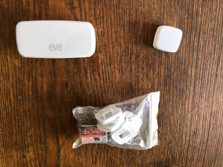
The Eve Door & Window consists of two pieces (one of which holds a small battery) that compose what’s known as a contact sensor. When the two sensors are close, they report to HomeKit that they are closed. When they’re apart, they read as open.
The package consists of the two sensors, the battery, and a series of spacers, which you may need to use to line up the sensors just so (Figure 41).
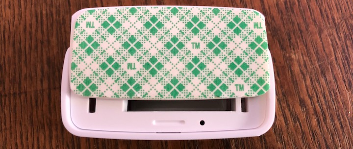
First, install the battery in the larger of the two sensors. Maybe I’m not the brightest Hue bulb, but I had a bit of trouble figuring out exactly how you remove the cover, since it’s covered by a sticky pad—the trick is to slide it up, as I demonstrate in Figure 42. As for installing the battery, align it so the flat end meets the spring—pretty standard stuff.
Next, set up the Eve Door & Window in the Home app (refer to Set Up Accessories if needed), because that makes testing and placement easier. Note that the Eve Door & Window supports notifications, as I discuss in Tweak Accessories.
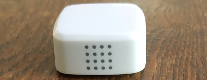
With the Door & Window powered on and configured in Home, take a look at each sensor and locate the series of holes that resemble a speaker grille. It’s easiest to see them on the small sensor (Figure 43)—on the larger one, they’re covered by the HomeKit code sticker, but you can still see them if you look closely in good light. Behind those holes are the actual sensors, and if you want the pair of sensors to work reliably, they need to be lined up as closely as possible when in the closed position.
Experiment with positioning the sensors on a desk or table where it’s easy and convenient to better see how they should fit together. The larger unit has a red LED on the front of it that lights up when they connect or disconnect. You can also observe the accessory button in Home, which tells you if the Door & Window sensor reads as open or closed (Figure 44).

Once you have a good sense of how the sensors should go together, study the door or window you want to install it on and figure out how the Door and Window can work with it.
You may find that you need to raise the little sensor a bit to get it to line up correctly with the big sensor. That’s where the six included spacers come in. They go on a sticky pad (with a rectangular cutout) on the back of the little sensor, but you must apply them in a particular order:
Spacer with a hole in the middle: If you need spacers, this one is mandatory. It sticks to the sticky pad on the back of the little sensor and provides a hole for the other spacers to snap into. Look for the little arrow next to the hole—that side needs to be facing out so the other spacers can click into place.
Spacer with a peg on one side and a sticky pad on the other: This spacer must be the last one in the chain. It clicks into the above spacer, and its sticky pad adheres to the surface.
Spacers with holes on one side and pegs in the other (3): If you need them, these spacers go between the first and last spacer.
In Figure 45, I try to demonstrate how these spacers go together. Hopefully with my guide and a little common sense, you’ll figure it out. If all else fails, use chewing gum.

Finally, it’s time to mount the sensors. The good news is that the little sensor is magnetic, so if you’re mounting it on a steel door, it’ll stay in place temporarily to make it easier to line everything up.
Line up your sensors so that one is in a fixed position and one is on the moving part. If you’re working with a door, you want the big sensor on the door jamb or frame and the little sensor on the door itself; on a window, you’ll usually want the big sensor on the window casing and the little sensor on the window that moves.
Line the sensors up so that the red LED on the larger unit lights up when the door or window is fully closed. Open and close the door or window repeatedly to make sure that the LED lights up every time you open and close it (Figure 46).

Once you know where you want the sensors, clean the surfaces so that the adhesive sticks well—I used a microfiber cloth and isopropyl alcohol—and then dry them thoroughly. Put the sensors back in place and use a pencil to outline their position.
Remove the sticker paper from the back of one sensor and place it where you marked it. Do the same for the other sensor. Test again to make sure that the LED still lights up every time you open or close the door or window.
That’s it, you’re done!
Work with Electricity Safely
Most HomeKit accessories require no tools for installation and, at worst, are as dangerous as any other appliance you plug into the wall. However, some more-advanced devices (including light switches, which I’ll be covering next) must be directly wired into your home’s electrical system.
If you’re uncomfortable doing that, then I highly recommend hiring a qualified electrician to install these accessories. However, tasks like swapping wall switches are easy jobs that anyone with a bit of caution and know-how can perform.
Here’s a quick rundown of the process, which I’ll detail more throughout this section:
Verify that the outlet or switch is receiving power and that your tester is functioning correctly.
Cut power to that circuit so you can safely manipulate the wires without suffering electrical shocks.
Verify that the outlet or switch is no longer electrified.
Perform the work you need to do.
Restore power to the circuit and test the connection. Make sure that there’s no arcing or other issues.
Choose the Right Tools
To do this sort of work, you’ll need a few basic tools. None are very expensive, and can be had for just a few bucks at stores like Harbor Freight, Home Depot, or Walmart:
Non-contact voltage detector: These are indispensable for electrical work around the house. They’re like an electric pen that can sense electrical voltage—press the button, hold it to the small plug slot on an electrical outlet, or to the screw terminals of a switch, and it starts flashing and beeping if the circuit is powered (Figure 47). They’re much easier to use and safer than a multimeter when you just need to make sure that a wire isn’t hot. If you need help choosing one, check out Wirecutter’s guide.
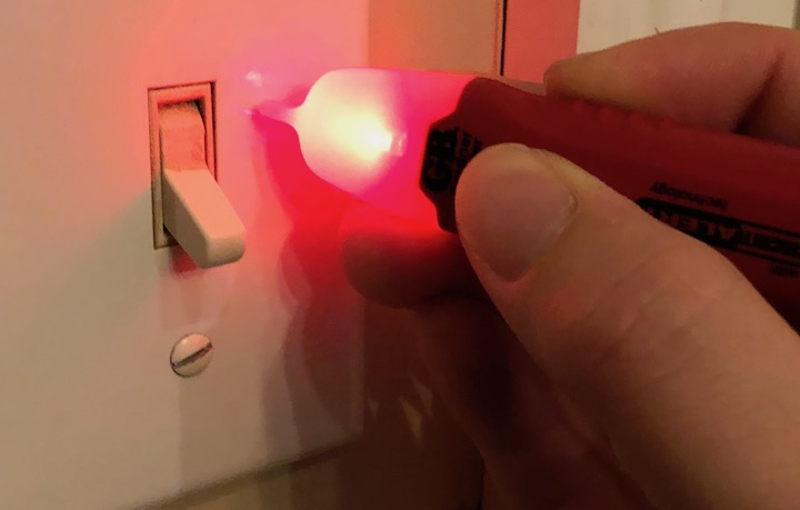
Figure 47: Ideally, you should remove the cover plate before testing the switch for power, but you can often pick up the voltage beforehand. If you can verify that the detector is working correctly and cut power to the switch before removing the cover, you’ll be that much safer. Plug-in outlet tester: I don’t go into outlet replacements in this book, but in case you ever do replace one, or just want to test one you have, these cheap gizmos are essential. Simply plug it into an outlet and see which lights turn on (Figure 48). Check it against the guide printed on the tester itself to make sure the outlet is working correctly. They’re easy to use and help prevent equipment damage and fire. Fire bad. I use one similar to this, but there are several kinds on the market.
Figure 48: I may never expect the Spanish Inquisition, but I can expect my electrical outlet to work flawlessly. Multimeter: Multimeters aren’t the easiest gadgets to use, but they’re an essential part of any electrical toolkit. They can measure resistance, capacitance, and voltage in AC or DC. You probably don’t need one for anything I discuss in this book, but they’re useful for checking for bad grounds, broken connections, low voltage, and various wiring problems. More-expensive models can measure all kinds of other stuff. You can spend hundreds on one, but you can find one with enough features for our purposes for under $10. I use this cheap one from Harbor Freight, which is best described as “sufficient,” and Harbor Freight often gives them away for free.
Needle-nose pliers: Home electrical work involves manipulating and twisting thick electrical wire, and there is no better tool for it than needle-nose pliers. Again, they don’t have to be expensive. Wirecutter has some recommendations here as well.
Wire strippers/cutters: Surprisingly, I don’t find that I need these much, because most of the wires I use come pre-stripped. I usually just use a simple pocket knife if I need to trim any insulation. Some needle-nose pliers have built-in cutters and/or strippers. Unsurprisingly, Wirecutter has recommendations for, uh, wire cutters.
Screwdrivers: You’ll need basic flat-head and Philips screwdrivers in a variety of sizes. Use the right size for the job so you don’t strip the screw head! Most electrical components, including light switches and wall outlets, as well as outlet and switch covers, use fairly standard screw sizes, so you’ll likely need only one flat-head and one Phillips.
Break the Connection
Before fooling around with electrical wires, you need to cut power to that circuit! In most modern homes that’s accomplished via a breaker box, which acts as a central panel for your home’s electrical circuitry. Each circuit is wired to a circuit breaker, which you can flip to turn on or off (Figure 49).

The trick is figuring out which breaker goes to the circuit you need to turn off. If your breaker box is well labeled, that’s easy. Otherwise, you’re going to have to use trial and error to figure it out. Here’s the method I’ve adopted, and it’s been serving me well for years:
Verify that the outlet or switch is receiving power and verify that your tester is working correctly. I test it with either a voltage detector or multimeter. If it’s a light switch, I turn it on. If it’s an outlet, I plug in a lamp or other simple electrical appliance and turn it on.
If you have a partner (highly recommended), have them stand by the test light—if they’re not in earshot, preferably with a phone or walkie-talkie so you can talk to each other.
If you have any electronics that don’t react well to having their power cut abruptly (for example, a computer without a UPS, a NAS, or some DVRs), be sure to shut them down gracefully before turning off any circuits.
Go to your breaker box and make an educated guess about which breaker it might be. If you have no labels to go on, work systematically by starting at one end and moving in a single direction. Flip a breaker off, see (or have your partner tell you) if your light is still on, and then flip it back on again. If the light turned out, you’ve found the breaker; if not, move on to the next one. (If the light isn’t in view and you don’t have a partner, you’re going to have to do a lot of walking.)
Once you have identified the correct breaker, make sure it’s off, then test the outlet or switch with your tester to ensure that the power is off. Bonus points if you label the breaker for future reference.
If worse comes to worse and you can’t figure out which breaker to kill, you can turn off the main power, which should be an extra-large breaker at the top of the box. That cuts power to your entire house, so make sure to have portable lighting on hand!
Install a Light Switch
Now that I’ve bored you to tears teaching you how to not die when performing electrical work, it’s time to put that knowledge to good use by showing you how to install a light switch.
As an example, I’ll use an Eve Light Switch. The Eve Light Switch replaces a standard single-pole in-wall light switch. If the light (or outlet) you want to control can be controlled by more than one switch—called a three-way (or even four-way) switch—the Eve Light Switch is not the solution for that light. The Eve Light Switch also requires a neutral wire—typically colored white. Don’t worry, I’ll show you how to find that.
There are three items in the box that I want to call your attention to:
The Eve Light Switch itself.
Four black wire nuts.
The manual, which has the HomeKit code printed on the back—put it in a safe place! There’s also a code on the switch itself, under the cover, but it’s better to have the code easily accessible.
There are four colored wires on the back of the Eve Light Switch. Each one corresponds to a wire that may be in your wall:
Black: This is the live wire, which is also usually black inside your wall. The live wire is always “hot” or receiving an electrical current. Here’s an easy way to remember black = live: if you touch a live wire, black is what your friends and family will be wearing to your funeral. Sorry if that’s dark, but you won’t forget it!
Red: Red goes to the load wire, which is sometimes black inside your wall. This wire doesn’t get hot until the switch is flipped to on.
White: The white wire is the neutral wire, which should also be white in the wall. White is a neutral color, so that’s easy to remember.
Green: The green wire is ground, which is an optional wire for the Eve Light Switch. If it’s present in your wall, it’s either a bare wire or a green insulated wire.
To understand how these wires work in comparison to a kitchen sink: live is the water pipe going into the sink, load is the faucet, the actual switch is the faucet handle, white is the drain, and green is an overflow outlet.
Now, with all of your electrical knowledge, let’s begin:
At the switch you want to replace, there should be two flat-head screws securing the wall plate. Remove them to expose the switch and its wires.
Carefully peek inside the hole in your wall and see what sort of wires are connected to your existing switch. Typically, you have two black wires (live and load) on one side, a white neutral wire on the other, and if you have a ground wire, it is connected at the top or bottom (Figure 50). If you do not have a white neutral wire, the Eve Light Switch will not work in that outlet; replace the cover and treat yourself to some Hue bulbs.

Figure 50: If you see this white wire, you’re in business! Assuming you have the necessary wires, now we need to verify electrical current and identify the live and load wires. Locate the screw terminals on the existing switch, which secure the electrical wires in place. With the switch turned to “Off,” take your voltage detector, hold down the button, and place the tip near those screws. The screw connected to the live wire should cause your detector to beep and flash (Figure 51).

Figure 51: Although the switch is off, power is still flowing to this terminal. That’s the live wire. Flipping the switch to on sends power to the load wire. Note the screws I’ve highlighted with green boxes—we’ll remove those in step 7. The other black wire adjacent to the live wire should be the load wire. Here’s how to tell: if there’s no voltage at that terminal with the switch off, but there is when you turn the switch on, that’s the load wire.
With the live and load wires verified, turn off the breaker to that circuit.
Test the switch’s wires with your voltage detector to ensure that there is no longer power flowing to it.
After verifying that the switch’s wires are no longer carrying current, remove the top and bottom mounting screws. Refer back to Figure 51, where I’ve highlighted them with green boxes. Note that your mounting screws may instead be in the little “ears” to each side of the highlighted screws.
With the switch physically unattached, gently pull it away to expose the terminals and wires.
Use a screwdriver to remove the screw terminals. The exposed ends of the electrical wire are wrapped around those terminals. You may prefer to merely loosen the screws and then unwrap the wires, but I always find it easier to remove the screws entirely.
If whoever wired your switch used plug-in wire connections instead of screw terminals, you’ll likely have to cut the wires from the current switch and strip back some insulation to reveal enough bare copper to connect it to the Eve Light Switch.
With the screws removed, you should have exposed wires sticking out. Be sure to note which wire is which. Write it down if you have to. Note how stiff the wires are—they’re not going anywhere!
Take your needle-nose pliers and gently straighten out the ends of exposed wire (Figure 52).

Figure 52: On the left, I have removed the screw terminal for the load wire. On the right, I have removed the terminals for the load, live, and neutral wires, removed the switch, and have used needle-nose pliers to straighten the exposed ends of wire. It’s now time to wire the Eve Light Switch—get the switch and the wire nuts ready. Here’s how to use the wire nuts to connect the wires:
Place a wire from the Eve Light Switch beside the corresponding wall wire, facing the same way, with the tips even.
Put the wire nut over the two wires and push firmly to seat them in place.
Turn the wire nut clockwise. You should feel it tightening. Keep turning until it feels good and snug.
Gently tug at each wire in the wire nut. If one comes loose, remove the wire nut by turning it counter-clockwise and pulling it off. Straighten any twisted wire and try again. Remain calm and be patient and you will be rewarded.
If there’s any bare copper sticking out of the back of the wire nut, consider wrapping it with electrical tape.
The Eve Light Switch should now be properly wired to your home. If you have a helper, it’s good to have them hold the switch and provide some support, but if you’re flying solo, it should hang by the wires just fine if you wired it correctly.
Here’s an optional step I like to take at this point: turn the breaker back on (if it’s a long walk, have a helper do it!) and make sure that there is no arcing, sparking, or other nastiness. When I installed my Eve Light Switch, I even checked the connections with my voltage detector—all three wires triggered it this time. If anything seems out of line, turn off the breaker and rewire the switch. If you’re struggling, don’t be afraid to call for help! An electrician’s bill is far less expensive than going to the emergency room or cleaning up a house fire!
If you followed the optional portion of step 12, turn the breaker back off!
Now is your moment of truth. Get the mounting screws for the switch (the two that came with your Eve Light Switch) ready, gently push the switch back to the wall, making sure to not pop any wires loose and trying to not cross any wires (Figure 53). If the wires in your wall are long, you may need to gently bend them to get them to fit behind the switch, especially because most smart switches and outlets are bulkier than the simple ones they replace.
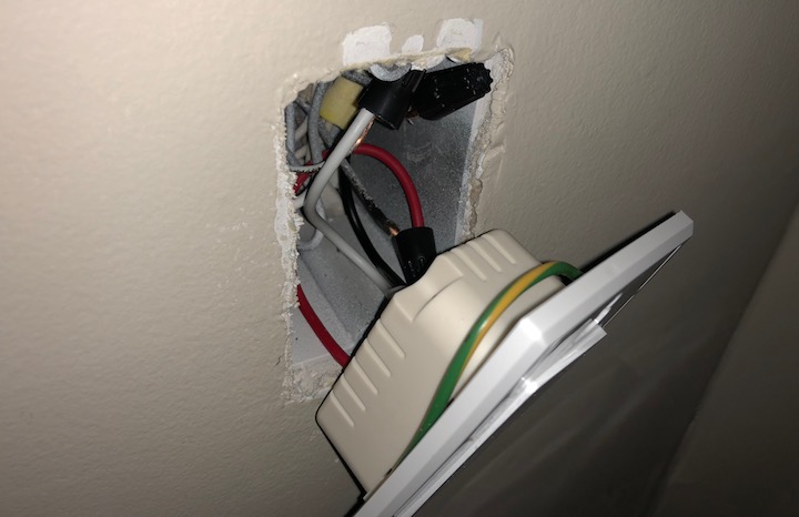
Figure 53: The wire nuts are securely connecting the wires. Note the bit of copper sticking out of the back of the nut on the live (black) wire—you should cover that with a bit of electrical tape. Also note that I didn’t need the switch’s ground wire, so I just wrapped it around the Eve Light Switch’s casing. This is a little tricky, but I’ll try to explain my technique. I push the switch up near the wall but leave a slight gap. I insert the screw through the mounting hole in the switch and use the gap to visually line the screw up to the mounting hole in the wall. I then turn the screw clockwise with my fingers to get it started and secure the switch in place. I then do the same for the other screw, and then finish with a screwdriver.
Turn the breaker back on.
Your hardware installation is done! The Eve switch is touch-sensitive—try it out! Tap it to turn the switch off and on—a green light should appear when it’s off.
Since the HomeKit code is exposed on the switch itself, before snapping the cover plate back in place, go ahead and set up the switch in HomeKit as I explain in Set Up Accessories.
Install a Thermostat
After lighting and outlets, probably the most popular category for home automation is thermostats. Adjusting the temperature of your house from bed is awesome! Having your thermostat schedule itself is great, too! Not only that, but a smart thermostat can help you spend less on heating and cooling.
I’ll explain how I installed an ecobee4 thermostat in my house. HVAC systems are complex and diverse, so the exact method for your home may be very different. Most smart thermostats include excellent documentation, and many companies provide additional information online or in the accompanying app. For example, the ecobee app includes useful graphical instructions—tap Install Your Device on the first screen after launching the app. And don’t be afraid to contact ecobee support if you run into a problem.
Installing a thermostat is the most complex installation in the book, so don’t be afraid to call an HVAC professional. I got my system running well, but it’s taken some tweaking and guesswork. Incorrectly installing a thermostat can really mess up your heating and cooling system, which can lead to expensive repairs!
Check for the C-Wire
Behind every thermostat is a series of wires, each represented by a letter. The C-wire is also known as the “common wire,” but in reality it’s not as common as would be ideal. In essence, the C-wire, found most commonly in newer HVAC systems, delivers more power to power-hungry thermostats like the ecobee.
You don’t need the C-wire to power an ecobee thermostat—the ecobee4 comes with a device called the Power Extender Kit (PEK), which is attached at the actual HVAC unit rather than the thermostat. ecobee offers installation instructions for the PEK, but I would recommend consulting a professional for two reasons: it involves working around high voltage, which can be dangerous to yourself and your HVAC system, and the PEK works by “stealing” power from other wires in your system, which could strain your system and shorten its lifespan. Take your chances if you like, but if I didn’t have a C-wire, I’d call a pro. I’ve heard from a few people who said they had a C-wire added inexpensively, which would be a better solution if it’s cost-effective.
Fortunately, figuring out if you have a C-wire is easy: just crack open your thermostat. Usually, this is as easy as pulling the cover off. But before you start yanking, look to see if there are any tabs you need to press or screws to remove.
Once you get the cover off, you should see a series of small wires connected to terminals as shown in Figure 54.
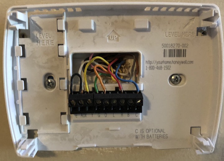
If you see a C-wire, you should be able to install the ecobee thermostat without any trouble. If you don’t see it, consult an HVAC specialist and discuss your options. They may be able to install a C-wire inexpensively, which would be a better solution than the PEK.
If you’re not installing the ecobee right away, go ahead and put your thermostat cover back on for now.
Prepare to Install the ecobee
Once you have your ecobee in hand, it’s time to review the included parts (Figure 55). Be sure to also read through the included instruction manual!
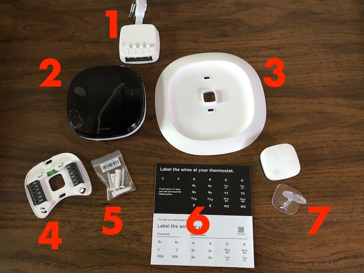
Here are the main parts of the ecobee4 (other models should be similar):
Power Extender Kit: If you don’t have a C-wire, you’d attach this to the actual HVAC unit to power the thermostat. I won’t be covering that procedure in this book.
ecobee thermostat: This is the actual unit that you’ll be interacting with on a daily basis. Be extra careful with this part!
Trim plate: Usually when you remove an old thermostat, it reveals holes and unpainted spots. If your old thermostat was larger than the ecobee, the ecobee may not fully cover these blemishes. This included plate goes between the ecobee and the wall to make things look nice. If the ecobee completely covers these flaws, you can ignore this piece—the ecobee looks better on the wall without it.
ecobee backplate: This is the part that is attached to the wall, to which you connect your HVAC system’s wires. The ecobee thermostat plugs into this part. If you use the trim plate, the backplate snaps into it.
Screws and drywall anchors: These are used to secure the backplate and trim plate to the wall.
Wire labels: These included labels are useful for labeling each of your thermostat wires as you disconnect them from the old thermostat—it’s a lot easier to connect them to the new thermostat if they’re labeled.
Remote sensor and stand: Higher-end ecobee models, such as the ecobee4, include one of these remote sensors, which can sense temperature and occupancy in other rooms in your house. The ecobee3 lite does not include remote sensors, but you can purchase them separately. See Set Up ecobee Sensors.
Before getting started, you’ll also want to have these tools:
Small flat-head screwdriver: You’ll need this to loosen the thermostat wires.
Drill and bits: You’ll need to make a couple of holes in your wall, and these are the best tools to do so.
Phillips-head screwdriver: Just a regular old screwdriver.
Needle-nose pliers: For manipulating small wires.
Hammer or mallet: Just in case you have a stubborn drywall anchor.
Now you have the parts and you have the tools. There’s one last thing to do before getting started: figure out how to wire the thermostat.
Get a scrap piece of paper. Make two columns: one for your existing thermostat and another for your ecobee (Figure 56). Take the cover off your existing thermostat, and in its column on the paper, write down the letter the wire is connected to and the color of the wire. Besides helping you plan out your wiring, it also acts as a reference in case you lose a wire label.
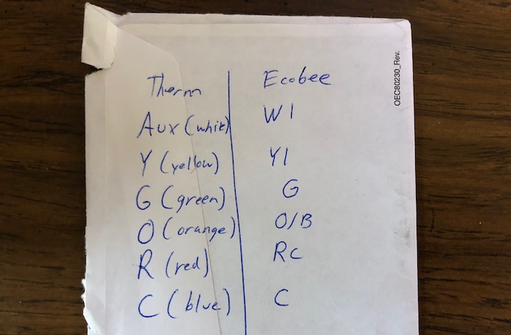
Next, look at your ecobee backplate and see which wires line up with your existing thermostat. On my thermostat, G, O, and C directly lined up with terminals on the ecobee backplate (my O wire lined up with the ecobee O/B terminal).
I had to consult the manual for the Y and R wires; the manual told me to connect the Y wire to the Y1 terminal and R to the Rc terminal.
But I was left with one mystery to solve: the white wire, which was connected to the Aux terminal on my existing thermostat, which was in turn jumpered to the E terminal (refer back to Figure 54). Fortunately, ecobee supplies several wiring diagrams on the company’s website, and I found this one that suggested connecting Aux and E to the W1 terminal on the ecobee. Additional research confirmed this to be correct.
Write all of this down so you can refer to it as you’re wiring your ecobee. Save it for later reference!
Remove Your Old Thermostat
Once you know how you’re going to wire your new thermostat, it’s time to uninstall the old one. This is a straightforward process, but some care must be taken.
First, turn the HVAC system off at the thermostat. The reason to do this is because when you’re setting up the ecobee, one of the first questions it asks you is what the old thermostat was set to, so the ecobee can sync to your system. Just turn it off to avoid any hassle.
Next, you need to turn off the breaker for both the inside and outside portions of your HVAC system. The risk of electrical shock from a thermostat is low, but the bigger risk is creating a short as you’re manipulating the wires, which could cause expensive damage to your HVAC equipment. It’s best practice to kill the power while you’re replacing the thermostat.
I explained how to cut breakers in Break the Connection. ecobee recommends testing the breakers by turning your thermostat on and seeing if any air blows out of the vent after the breaker is off. I was fortunate enough to have well-labeled breakers and a thermostat powered by a C-wire, so this part was easy—when I turned the breaker off, the thermostat also turned off.
Once the power is off, loosen each wire from the existing thermostat terminal by turning its screw counterclockwise, labeling the wire with one of the included labels, if you have a label for that wire (Figure 57).
Don’t bother removing any jumper wires unless ecobee recommends jumping two terminals on the ecobee unit. The manual instructed me to not jump any R wires that may have been jumped on the old thermostat, and I saw no reason to fool with the jumper wire connecting Aux and E on my old thermostat, because both of those corresponded with the W1 terminal on the ecobee. In many cases, the ecobee is smart enough to handle any required jumping via software.
Once all the wires are removed from the existing thermostat, it’s time to unmount the thermostat unit from the wall. As you can see in Figure 57, I just had to remove two screws.
Install the ecobee Backplate
At this point, you have a hole in your wall with colored wires sticking out, and you’re probably looking at some drywall anchors that held the old thermostat in place. Time to finish the job:
Decide whether you want to use the trim plate. Just hold the ecobee thermostat up to the wall to see if it would completely cover the unpainted spots (Figure 58). If it won’t, and you won’t be patching and painting the wall right now, you should use the plate.
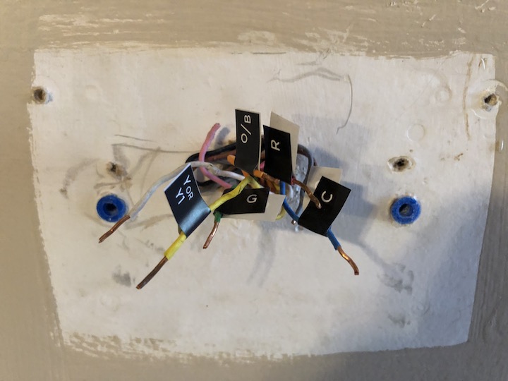
Figure 58: The ecobee thermostat without the trim plate wasn’t enough to cover this mess! Note the unused wires that I’m ignoring. You also probably want to remove any unused drywall anchors to ensure an even surface for the thermostat and plate to rest on. I’m going to assume that you’ll use the trim plate. Fortunately, pairing the backplate to the trim plate is easy: just line up the square holes and snap them together.
You need to mount the backplate to the wall, with or without the trim plate attached. To do so, first you need to line up the backplate with the wall. Chances are that your wires are all over the place after detaching them from the old thermostat and labeling them. Carefully arrange your wires into a neat bundle that will fit through the hole in the backplate and/or trim plate.
Thread the wires through the backplate hole so that the plates sit flush against the wall. The first time I tried this, I didn’t thread the unused wires through, so it wobbled a bit. If you have unused wires, thread them through, as well.
Once the wires are through, and the backplate is flush against the wall, level out the plates and mark where to drill the mounting holes.
Usually when you install a thermostat, you have to balance a level on top of the unit when you’re lining it up. But many modern thermostats, including the ecobee, include a small level on the backplate! Just rotate the plate until the bubble is perfectly centered between the two lines.
To mark the location of the holes you’ll need to drill for the mounting screws, I recommend taking one of those screws, putting it through one of the two holes, and gently pressing the tip against the drywall; repeat for the other hole. Then take a sharp pencil, find the indentation, and mark it with the pencil lead. Remove the plate(s) from the wall.
Before you grab your drill, let’s talk mounting solutions. If you have wood paneling or some other sort of solid wall surface, or if there happens to be a wall stud behind one of your mounting marks, you won’t need to use the included drywall anchors for those screws—just drill a pilot hole and then screw them into the wall.
But most modern homes have chalky drywall, which is cheap, easy to paint, attractive, and easily repaired, but can’t hold much weight. So they invented these little plastic doodads called drywall anchors. You drill a hole in the drywall just big enough for the anchor’s tip to go into, and then place the tip of a screwdriver into the hole on the anchor and screw it into the wall. You then insert the screw into the opening on the drywall anchor—the anchor helps support the weight of whatever you’re screwing to the wall. Refer back to Figure 58—the drywall anchors are those blue things in the wall.
You always need drywall anchors when screwing stuff to drywall unless there’s a stud—a 2x4 piece of lumber that serves as part of your wall’s skeleton—behind one of your mounting holes. When drilling, you’ll know you’ve hit a stud if you have an especially hard time drilling and/or you see wood chips on the drill bit’s flutes. Its unlikely you’ll hit a stud here, but contractors make odd decisions sometimes when framing houses.
With an understanding of wall fixtures under your belt, pick up your drill and choose a bit. ecobee recommends a 3/16" bit if you’re using the included wall anchors. Always start with the smallest bit and work your way up, because it’s much easier to widen a hole than it is to undrill it! I started with a 3/32" bit and worked my way up.
In theory, if you’re working with drywall, this is how this should work:
Drill a 3/32" hole in each of the spots you marked with a pencil.
Insert the tip of the included drywall anchors into holes.
Insert a Phillips screwdriver into the hole of the drywall anchor and turn the screwdriver clockwise while putting gentle pressure on it.
Once the flared edges of the drywall anchor are flush to the drywall, put the ecobee plates back into position, carefully threading the thermostat wires through the center hole, insert each included screw through the holes in the backplate into the hole in its corresponding drywall anchor, and use a screwdriver to tighten the screws to affix the thermostat to the wall.
Once the plate(s) are affixed to the wall, tug them gently to make sure the backplate is not going to fall off and break your fancy thermostat (and probably take a chunk of drywall with it). Don’t try to do pull-ups here—just make sure that the plate(s) are secure to the wall.
Now it’s time to put the wires into the terminals. Take one wire at a time and insert its bare tip into the side of the proper terminal (Figure 59). Each terminal has two holes: one in the front and one in the side. Do not stick the wire in the front hole, as those are where the pins on the back of the actual thermostat go.
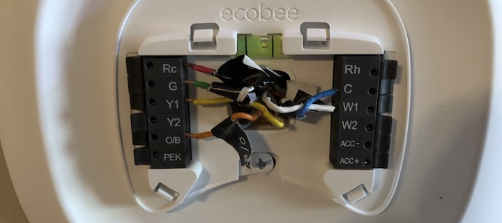
To insert the wire, just stick the bare end into the side hole and push it in until you feel a click. Needle-nose pliers are useful here for pushing the wire in firmly. As you insert the wire into the terminal, the little lever at the opposite side of that terminal should depress itself and then pop back into position. Some of mine stayed depressed, probably because the wire tips were so long. Regardless, they seem to be well in place.
If a wire seems too short to get far enough into a terminal to click, try gently pulling it until you can get the end locked into the terminal. I had to do that for my G wire. (If you put the wrong wire in a terminal and need to remove it, just press the little lever to release the wire.)
When finished, gently tug each wire to make sure it’s not going to pop out on its own.
If you did everything right, the hard part is over!
Finish the ecobee Installation
Take the thermostat (the black, shiny part) and push it onto the wall plate. Look at the back of the thermostat. See those little pins? They go into those front-facing holes on the backplate, the ones that you weren’t supposed to stick wires in! It should be as simple as pushing the thermostat in place until it clicks. Very gently wiggle the thermostat to make sure it’s secure.
Now is the moment of truth. Turn the breaker back on, and your ecobee should turn on and say “hi,” followed by “please give me a moment while I stretch my wings” (Figure 60).

If the thermostat doesn’t turn on, double-check your wiring, contact ecobee support, and/or call an HVAC professional.
Now the ecobee guides you through HVAC configuration. It first asks questions about the thermostat wiring, which you should know the answers to.
It then asks if you have an accessory connected to your thermostat, like a humidifier, dehumidifier, or ventilator. You likely do if you have an ACC wire. Follow the onscreen instructions to set that up or seek additional help.
Next you’ll be asked if you want temperature in Fahrenheit or Celsius. Choose wisely.
If the ecobee asks what type of heat pump you have, you can choose air to air or geothermal. It offers some guidance here, but I’d assume you’d know if you had a geothermal unit, since they’re somewhat rare.
Next is a very tricky question: is your O/B reversing valve energized on cool or on heat? The good news is that getting this wrong won’t damage your system, but if you choose incorrectly, you’ll get cold air when you want heat. Follow the ecobee’s advice and set it to “Energize on cool” at first, since that’s the most common configuration. If that turns out to be wrong later, you can go back to the settings screen on the thermostat and go to Settings > Installation Settings > Equipment > Heat Pump > O/B Reversing Valve to change it.
Next up is another tricky question: let the heat pump and aux heat run simultaneously? The ecobee warns to set it to Disable if your auxiliary heat is natural gas or oil. My auxiliary heat is an electric heat pack, so I enabled it to allow smoother transition between my electric heat pump and my electric heat pack.
Next you’re asked the minimum outdoor temperature for your compressor, assuming you have one. The default is 35°F, which is a safe default for an air-to-air pump. Any colder and the ecobee turns off the heat pump and switches to auxiliary heat to avoid damaging the pump.
The next question is likely whether you have a furnace or a boiler. Choose appropriately for your home.
Next, you may be asked whether you want your fan to be controlled by the ecobee or the furnace. ecobee recommends that it should control the fan, but I found that caused cold air to blow out of my vents when I turned the heat on, and it’s apparently a common problem. I recommend setting this to By Furnace; you can always switch it back later.
You’re asked to name your ecobee. Choose what you like—I just went with the default My ecobee because it’s descriptive, and it hasn’t given me any problems. If you have a multi-zone HVAC system, you probably want to give the ecobee a name that describes where it is in your home, like Bedrooms.
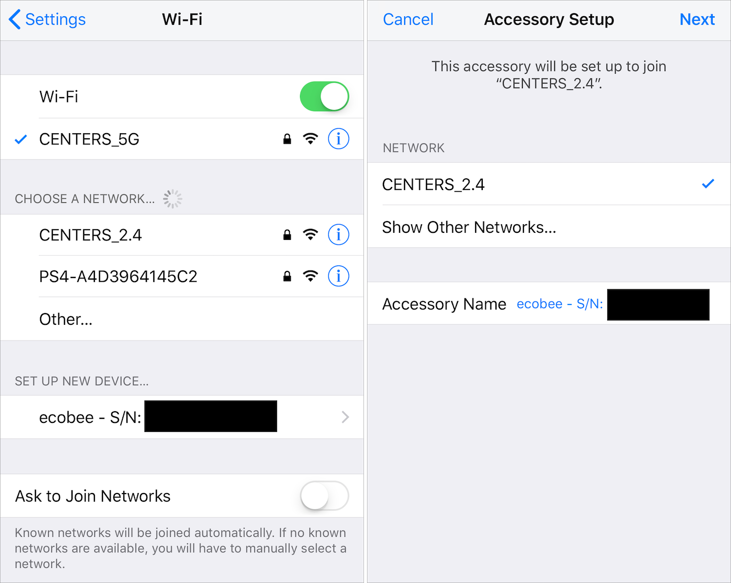
Next you’re asked to set up Wi-Fi access for the thermostat. The easiest option is Use iPhone, iPad, or iPod. You’ll be prompted to go to Settings > Wi-Fi on your iOS device and choose the ecobee under Set Up New Device, followed by choosing the Wi-Fi network (Figure 62).
After Wi-Fi is established, you’ll be asked what the current mode of your HVAC system is. If you followed my advice, it should be Off. Otherwise, see if you can tell from looking at your old, disconnected thermostat.
You’re asked ideal home temperatures during summer and winter. Enter what you like here.
You’re prompted to enable Smart Home/Away. Some ecobee models can detect home occupancy (via motion detectors in the thermostat and remote sensors), and they use that information to automatically set Home and Away settings to reduce energy usage when no one is home. I find that this works pretty well, but Disable it if you’re unsure.
You’re asked to choose your country of residence and time zone, and then you’re presented with a registration code that you’ll use to connect your thermostat to the ecobee service, which is required to connect it to HomeKit. Be sure to save this code!
At this point, your thermostat is set up, but it will not be operational until the calibration process is complete. This only took a few minutes for me, but some users report it taking several hours.
Connect ecobee to HomeKit
Don’t bother digging through the ecobee packaging for a HomeKit code. The only way to link the ecobee thermostat to HomeKit is to do so via the ecobee app, which involves linking your thermostat to ecobee’s online service.
When you first open the ecobee app, you need to enter the registration code you were given when you set up the thermostat. If you didn’t save that, don’t fret—tap the menu ![]() button on the thermostat followed by Registration and Continue to view it again. Tap Finish on the thermostat when you’re done.
button on the thermostat followed by Registration and Continue to view it again. Tap Finish on the thermostat when you’re done.
After you use the app to set up an ecobee account, you’ll be asked whether you want to enable the weather service, which lets you check the current weather and forecast on your thermostat. I like to turn this on because it’s a handy feature. At the next screen, when you’re asked for your address, you don’t have to enter your full address—just the city and state to get a weather report.
You’re asked whether to enable Home IQ, which lets you track system usage and energy consumption on the ecobee web portal. I left it on, but if you’re particularly privacy conscious, you may want to turn it off. If you turn it on, you’ll have to provide details about your home such as the square footage. If you don’t have that handy or don’t want to provide that, leave Home IQ off.
If you’re using an ecobee4, which has Amazon’s Alexa voice assistant built in, you’re prompted to set it up by linking to an Amazon account.
Once the app is set up, you can finally set up HomeKit. Refer to ecobee’s website for the most up-to-date instructions.
Use the ecobee
If you’ve read Use Accessories, you shouldn’t have much trouble controlling the ecobee thermostat, but I’ll offer some quick tips here:
Sync between the ecobee app and HomeKit is nearly perfect, so feel free to control your thermostat with whichever is more convenient at the time.
The ecobee is designed to let you set up schedules, using the app, based on when you’re home, away, or asleep, which are called Comfort Settings. To configure these, choose your ecobee in the app, tap the menu
 button at the bottom of the screen, and choose Schedule. Tap the plus
  button to add a new schedule item. Choose a comfort setting (by default: Home, Away, and Sleep) and a start time, and tap done.
To manually control your thermostat with the Home app, tap the ecobee’s accessory tile. Use the wheel to switch between Off, Heat, Cool, and Auto. (Auto lets you specify thresholds that turn on the heat or the air conditioning.) The slider lets you set the desired temperature.
While you can create regular scenes in the Home app, creating them in the ecobee app lets you call upon your Comfort Settings. To do so, go to the Account screen, tap HomeKit, tap Scenes, and then tap the plus
button in the upper-right corner.
Set Up ecobee Sensors
The ecobee4 includes a separate room sensor, which you can also purchase separately or in bundles of two if you want additional sensors, or if you have an ecobee3 lite. Each of these small, battery-powered sensors detects occupancy (via movement) and temperature. You can set them up to help the ecobee balance out the temperatures in occupied rooms, and to allow the ecobee to automatically switch between Comfort Settings based on whether or not someone is home.
Setting up room sensors is easy. Just flip one over, pull out the plastic tab to turn it on, and pop off the battery cover. Notice how the battery cover has a hole in it. That’s so you can use the included screw and anchor to install the sensor on your wall. If you don’t want to do that, replace the battery cover with the included stand, which just pops into place. Wherever you place the sensor, keep it out of direct sunlight, but in a frequently trafficked area so it can pick up movement—near a doorway is good.
To finish setup, return back to the thermostat and follow the onscreen prompts to set up the sensor and pick which room it resides in.
Troubleshoot the ecobee Thermostat
If your ecobee gives you much trouble, I highly recommend using ecobee support or contacting a qualified HVAC technician. But there are often issues you can quickly fix yourself.
Here’s how to fix common ecobee problems:
Various issues—check the wiring: It’s possible that a wire isn’t fully inserted in its terminal without being obvious from a visual inspection. Thankfully, the ecobee itself can tell you which wires are connected: from the thermostat main menu, check in Settings > Installation Settings > Equipment > Wiring.
Cold air when you want heat: First, understand that it may take your heat pump a few minutes to get up to temperature, especially if it’s very cold outside. To make sure that your vents aren’t blowing cold air, I find that an infrared thermometer like my Etekcity Lasergrip is handy. If the temperature at the vent is higher than it is around the vent, I know for sure I’m getting warm air, and I can track it getting warmer over time.
If you’re not getting warm air, or if it never seems to get warm enough, here are a few things I would check:
When you set up the thermostat, if you were asked if the O/B reversing valve energized on cool or on heat, go to Installation Settings > Equipment > Heat Pump > O/B Reversing Valve and change it to the opposite of what it’s set to. If cold air is still coming out of the vent when you want heat, switch it back, because that wasn’t the problem.
During setup, if you set it so that the thermostat controls your fan, I’ve found that often the ecobee kicks the fan on well before the pump is putting out warm air. Try setting it so that your HVAC system controls the fan instead in Installation Settings > Equipment > Furnace > Fan Control in Heat Mode.
By default, the ecobee keeps the fan on for a few seconds after the heat has stopped in order to circulate the remnants of the heat in your ducts. I personally don’t like this; you can turn it off in Installation Settings > Thresholds > Heat Dissipation Time.
If it’s very cold outside, it’s possible that your heat pump can’t work efficiently enough to keep you warm. Consider locking it out below a certain temperature in Installation Settings > Thresholds > Compressor Min Outdoor Temperature.
Aux running too long: If you have auxiliary heat and get a message complaining that it has been running too long, there may not be any reason to be concerned. If it’s super cold, your auxiliary heat runs more! You can adjust the threshold for the warning in Reminders & Alerts > Preferences > Aux Heat Runtime Alert. But if you’re worried that it actually is running too long, here are some things to try:
Check your heat pump lockout temperature in Installation Settings > Thresholds > Compressor Min Outdoor Temperature—it may be too low. Refer back to This COP Can Save You Money to learn how low you can set your lockout.
If your aux is running too long when it’s relatively warm outside, lower your Aux lockout in Settings > Installation Settings > Thresholds > Aux Heat Max Outdoor Temperature.
It’s also worth checking Settings > Installation Settings > Thresholds > Compressor to Aux Temperature Delta, which controls “the minimum number of degrees from the desired temperature before engaging the auxiliary heat.”
Also look at the Settings > Installation Settings > Thresholds > Compressor to Aux Runtime, which sets the “maximum number of minutes running the compressor before engaging the auxiliary heat.” If you set this too low, the heat pump may not have a chance to get up to temperature before turning on the auxiliary heat.