2
Whole life carbon – practical application
Reducing embodied and whole life carbon through the RIBA work stages
It is possible at every RIBA stage to examine options to reduce the whole life carbon cost of a building.1 To optimise the overall carbon reduction potential of a project, each stage should be considered from the outset. Every building should be thought of as an organism that evolves over time after it is ‘finished’; the architects and engineers who design it are responsible for setting up the most carbon-efficient process for the building’s whole life. The following is a summary of how a ‘carbon consultant’ (CC) might work within a project team. Chapter 6 sets out the calculation methodology for each of the BS EN 15978 modules. This methodology would be used in the context of RIBA project stages as explained below.

Figure 2.01: RIBA Plan of Work 2013 – stages.
RIBA STAGE 0 – strategic definition
The starting point is a client decision to include embodied and whole life carbon (WLC) accounting within project objectives as a key performance indicator – a choice that clients are increasingly making. The principal reasons for undertaking WLC assessments include: producing a specifically low carbon building, futureproofing asset value by pre-empting changes in standards and legislation, marketing advantages, corporate social responsibility, circular economic considerations, added value, resource efficiency, or a genuine desire to reduce the impact on climate change.
RIBA STAGE 1 – preparation and brief
WLC would typically be seen as part of ‘sustainability aspirations’ within the project objectives. It would therefore be necessary to define for the project team what must be achieved through WLC assessment. Implicit in WLC is life cycle assessment (LCA). This encourages the design team to engage with long-term thinking about the building’s fabric and functional performance past practical completion. A carbon consultant must be selected to provide the required level of advice.
This should ideally cover all modules (ie A, B, C, D) of BS EN 15978 (for more detail see Chapter 6), and all RIBA stages.
RIBA STAGE 2 – concept design
WLC thinking should be embedded within the design process from the outset. Even at a conceptual stage, the issues of materiality and life cycle thinking play their part. LCA considerations such as climate change, future building flexibility, intended life and durability, materiality, deconstruction and disposal are all relevant to concept development. The carbon consultant can assist with concept development by providing comparative WLC assessments of various building fabric options being considered, as well as the carbon cost/benefit relationship with operational environmental strategies. WLC analysis can contribute to BREEAM 2014, specifically: Mat 01 Life cycle impacts; Mat 04 Insulation; Man 02 Life Cycle Costing; Ene 01 Reduction of energy use and carbon emissions; Wst 01 Construction waste management; Wst 02 Recycled aggregates.
Generally, design teams have little or no experience of embodied and whole life carbon reduction. It is therefore important for the carbon consultant to start with a team workshop to explain the process, issues and what is required. This form of introductory communication is key to success.
RIBA STAGE 3 – developed design
WLC analyses of the more detailed options under consideration – typically structural and envelope options – and the relationship with the building’s proposed environmental performance should be undertaken. The carbon consultant should be working closely with the project team. A ‘carbon budget’ should be prepared using the stage 2 or stage 3 cost plan’s material descriptions and quantities. This will form the baseline carbon budget against which improvements can be judged. A life cycle analysis will be undertaken to enable an assessment of the carbon life cycle costs over the building’s desired lifespan. This LCA should be synchronised with any life cycle costing (as part of Man 02, usually by the QS). The carbon budget can be presented as a total carbon cost and/or as a m2 rate. Typically a list of detailed options and their impact on the carbon budget would be prepared to enable the design team to choose low carbon, and preferably cost neutral, options.
WLC can contribute to planning applications, although even the most enthusiastic local authorities are usually not yet familiar with, nor yet have policies to accept, embodied carbon savings in lieu of shortfalls against Part L. SCP has had some success in using embodied savings to offset operational shortfalls.
The last part of this chapter contains two case studies, on structure and cladding. These are examples of the detailed thinking that can contribute to better design choices.
RIBA stage 4 – technical design
Low carbon choices made during stage 3 are now integrated into the detailed drawings, specifications and tender documentation, with further support from local assessments. The carbon budget should be updated and included within the tender documentation. It is important that the tender documentation ensures that the tendering contractors understand the WLC requirements, the goals, and the process of delivering and monitoring carbon reductions during construction. This process needs to be tailored to engage with but not burden the supply chain.
Low carbon strategies developed at the design stage will come to nothing unless they can be delivered during procurement. With any tendering process there are a number of actions that can facilitate this. Whatever the procurement route, and particularly with design and build, it is vital that the tender documentation includes clear and understandable WLC information.
It is also important to ensure that the way carbon-related information is asked for during tender does not increase project costs. Generally, if tendering contractors are engaged in the process from the outset, it is not difficult for them to buy into a low carbon process. In fact, many contractors are enthusiastic and contribute to what is essentially a resource efficiency exercise that is as beneficial to them as it is to the client or the planet. Education and early explanation of requirements is crucial, as for many main contractors, and certainly for those in the supply chain (tier one and tier two subcontractors), this is new territory.
RIBA stage 5 – construction
The key issue is monitoring the actual carbon impacts of the construction process against the carbon budget, and what has been agreed on completion of the tender process. To ensure continuing focus, and depending on project size and scope, reporting at intervals of every three to six months ensures that problems or proposed design changes can be managed from a carbon perspective. In this sense, monitoring the carbon budget is not dissimilar to monitoring the construction costs. Proposed WLC and life cycle impacts of variations can be brought to the client’s attention.
Efficiency and carbon emissions reduction go hand in hand. Efficient construction entails efficient use of resources, which reduces both costs and carbon emissions. Monitoring the delivery of commitments made during design and procurement is essential to ensure delivery of a low carbon building. The pressures of programme and cost can conspire to water down these commitments. Client support is crucial, and with design and build in particular it is necessary to create contractual mechanisms to ensure enforcement of targets. Typically, with good early engagement, most contractors see these issues as beneficial to them as well as the client.
RIBA STAGE 6 – handover and close out
Post practical completion, the carbon consultant should undertake a final review of the ‘as built’ information and produce a final assessment of the WLC impacts of the completed project.
The final version of the LCA should be included within the O&M manual. The final assessment should be compared to the initial budgets so that lessons can be learned.
As with any process requiring positive action, verification and assessment of the completed product is vital. Knowledge of the post-completion assessment requirement helps ensure compliance. The completion assessment can include certification that a certain embodied carbon footprint has been achieved.
RIBA Stage 7 – in use
Any post-occupancy evaluation (PoE) should take account of the WLC impacts. This should include the fabrics’ physical performance, and an assessment of maintenance regimes.
Buildings are living things in the sense that they change and deteriorate in response to environmental impacts and the actions of the occupants. How a building evolves over its life is very much down to decisions made at the design stages. The carbon intensity of maintenance, repair and refurbishment can be substantially affected by both the initial design solutions, and the regimes in place to manage the building. The latter is similar to environmental control systems, which, if poorly managed, can substantially increase running costs.
Low carbon design choices
Design choices made at each RIBA stage will affect the carbon cost of the final building. The following gives some idea of the considerations that help to achieve low WLC outcomes. Low carbon design is a state of mind that should ideally become second nature, to the same extent as designing for gravity, rain and sunlight.
Existing resources
Establish which materials, structure and fabric already on site are suitable for reuse within the project. Retention of structure and major components are significant benefits as they remove demolition, transportation of waste, disposal, new fabrication, more transportation and construction of new components from the carbon cost equation. Recycling of existing material within the scheme is the next best thing, provided that it results in lower overall emissions compared to new. Recycling that involves carbon-intensive transport away from site, energy-intensive reworking, and transport back to site, will probably not contribute to a lower footprint, even if the recycled content proportion looks high. Existing resources for which there is no further use should be disposed of as efficiently as possible, preferably for beneficial recycling (for which there are an increasing number of material-specific recycling companies, and websites such as Recipro-UK.com).
Part of the conceptual approach is to consider what the next architect/engineer would do with your building when it comes to future refurbishment. Can your building be dismantled and recycled in its entirety? Can the components be reused at the same level, ie not just at a lower use level? The ideal is for nothing to be wasted, and everything to be reusable.
Designing for flexibility from the outset makes it easier for a building to be reused in its entirety in a different use class. This also presupposes a high level of durability in the external fabric, as well as architectural design quality. Well-designed buildings have social and economic benefits for both the occupier and the locality. People enjoy good architecture and that contributes to its retention, whereas poor architecture is often rejected by society, leading to early demolition (a very poor carbon outcome).
In conclusion, resource-efficient low carbon design should start with what is available on site for reuse. This is not often done; our cultural demand for the new produces vast amounts of unnecessary waste.
Environmental strategy
The relationship between operational and embodied emissions and their collective mitigation is key to a low carbon building. Mechanical systems not only use energy but require maintenance and replacement on a relatively short life cycle. Fabricating, transporting and disposing of such systems is energy- and carbon-intensive. Passive systems are therefore sensible for both operational and embodied emission reduction.
The performance of services and the relative merits of different environmental systems are not the subject of this book. However, the carbon cost of installing and maintaining services is an important feature of a building’s lifetime carbon cost. Mechanical systems are energy-intensive to make, and do not have a long life expectancy. Central plant is usually replaced after 20–25 years, as are lift systems. Most sophisticated heating, cooling and renewable energy systems have comparatively short life expectancies (15–25 years). In addition, the materials that go into fabricating mechanical systems are often high quality and high on embodied energy fabrication costs. This combination of high initial carbon cost and short life expectancy, in addition to the operational running costs, means that mechanically managed environments are very poor carbon performers on all fronts. Efficiently designed building fabric and ‘natural’ strategies reduce or even omit the need for mechanical systems.
The corollary is that buildings that manage their environments without the use of mechanical systems have lower overall whole life carbon footprints. Omitting mechanical systems omits a large part of a building’s regulated operational energy use, and the embodied costs of the plant. However, the equation is incomplete without factoring in the carbon costs of naturally ventilated or renewable energy systems. The Everyman Theatre in Liverpool (2014 Stirling Prize winner) has large brick towers to provide a natural ventilation strategy. These have a carbon cost (mitigated by using recycled brick already on site) but also a very long life expectancy. Both the lifetime carbon and financial costs will therefore be low.
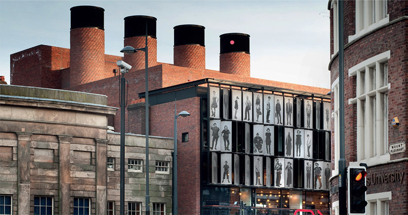
Figure 2.02:
Everyman Theatre, Liverpool.
A whole life carbon analysis of a project will examine the carbon cost, including any support infrastructure, of the proposed renewables in relation to the carbon benefits over the life expectancy of the project. It is a simple matter of comparing costs and benefits from the carbon emissions perspective. Typically cost/benefit analysis with respect to renewables is purely financial, and omits the carbon cost/benefit, which can be misleading.
Primary structure
The structural systems for buildings are many and varied. All systems have a carbon cost to source and assemble. However, the key to a low carbon structural strategy is to select the optimal system not just for the immediate requirement, and for the desired life expectancy, but also for future flexibility. This means optimising use of recycled content and considering the ultimate potential for reuse, either whole or in components. Many architects, such as Waugh Thistleton, Hopkins, PLP and SOM, are challenging preconceptions as to what this means and are exploring ways of using timber as primary structure in large buildings.
Some solutions such as steel or timber can be designed for easy dismantling and reuse. Concrete, using cement replacements, recycled content in steel, and recycled aggregate can be relatively carbon-efficient, particularly if durability and long life are required. Post-tensioned slabs use less concrete than a regular flat slab or reinforced concrete slab and deck combination, but are also less flexible for future adaptation such as creating new voids or moving shear walls. Typically, these structural choices are determined by the cost and procurement options around the initial construction, and not by longer-term, post-completion considerations. Owner-occupiers are best placed to take a long-term view; however, the design and construction industry does not generally provide life cycle choices to such clients, nor act to ensure that such buildings are designed for an efficient or evolving life past practical completion.
Structure-related emissions reduction strategies are important for achieving low carbon buildings since that is where, proportionately, most of the carbon reductions can be found.
Case study 1 is a comparative analysis of several structural systems from the carbon footprint perspective. It shows the issues that should be considered when determining the carbon cost of structural options.
External walls and cladding
The design of the external skin has a variety of performance demands: environmental, cost and aesthetic. It is directly linked to the environmental management of the internal spaces, and whether the building is passively or mechanically ventilated. There are several principal parameters that need to be considered in relation to optimising the overall (embodied and operational) performance of a facade. These are the initial embodied carbon costs of construction, the lifetime embodied carbon costs through maintenance and disposal, the potential for deconstruction and reuse, and the lifetime operational performance costs consequent on the design. The relationship between these parameters depends on required life expectancy and desired lifetime performance. Inappropriate choices can have significant unnecessary carbon costs.
The Library of Birmingham, a 2014 RIBA Stirling Prize finalist, uses what is essentially an office cladding system with circular aluminium decorative elements. This type of system typically has a life expectancy of no more than about 40 years. The owners will also have to deal with the significant financial and carbon costs of replacing the cladding after this short timeframe. The redundant materials will have to be disposed of (preferably recycled), and the owners will have to consider how to re-clad the building under what is likely to be a much more stringent regulatory regime. A more robust facade might have had a higher initial carbon cost but, if it lasts longer and is capable of incremental repair (ie replacing windows in a ‘hole in wall’ typology), then it may be the most carbon-efficient solution in the long term. The Birmingham example is, sadly, representative of the short-term thinking typical of much contemporary architecture.

Figure 2.03:
The Library of Birmingham – a public building using a comparatively short-life, office-type, powder-coated aluminium cladding system.
Another 2014 Stirling Prize finalist is the Shard in London, which has a unitised double skin (single- plus double-glazed) cladding system designed to provide operational performance benefits. However, the Shard houses a variety of uses (offices, residential, hotel, retail), all of which have different lease lengths. What will happen to the occupants when the cladding has to be replaced in 40-plus years’ time? This will entail a carbon and financial cost at a time when, in accordance with the low carbon transition plan, the UK should be achieving 80% CO2 reductions against 1990 levels. The facade’s unitised system gives the Shard a further disadvantage. Unitised systems typically interlock across an entire building, making it difficult – if not impossible – to replace part of the cladding in line with lease expiries.
It is interesting to compare the Shard with One Canada Square, the Canary Wharf tower, which was completed in 1990. This has stainless steel cladding but with a ‘hole in wall’ elevation so that the high-performance windows can be individually removed and replaced. This means that incremental upgrading, ie floor by floor, can happen in sync with lease cycles or even deterioration of sections of the facade. The stainless steel cladding has a comparatively high carbon cost of production, but this is mitigated by its very long life expectancy. Overall, One Canada Square’s cladding strategy seems more carbon-efficient, flexible and financially efficient in the long term than the Shard’s.

Figure 2.04:
The Shard (2014). High carbon investment, limited lifespan (approximately 40–50 years) cladding. The unitised system makes incremental replacement very difficult.

Figure 2.05: One Canada Square (1990). This building has been designed with ‘hole in wall’ type cladding. Individual windows or floors can have windows replaced to suit lease cycles.
The idea that it is acceptable for major new buildings to have a short life expectancy is a relatively recent one. The construction of a new building takes a significant amount of material and energy resources, so the life expectancy of the finished item and how it is disposed of have great importance from a carbon emissions perspective. When it comes to buildings with very short life requirements, the maintenance aspects are less important; the focus should be on low carbon materials for the initial construction, the potential for dismantling and reuse for the whole building, and/or recycling of components and systems. What happens to the building when it is no longer required should be an integral part of the initial design philosophy.
An interesting example of short-term building is the Serpentine Pavilion, the annual temporary art gallery in London’s Kensington Gardens. This is always a signature building showcasing the latest in design thinking; in 2016 it was designed by the Danish firm BIG. The pavilion represents a carbon investment in a building that is required only for a short period. What it is made of, what the construction emissions are and what happens to it once it is no longer required are all relevant questions in a post-COP 21 world.
What is instructive about the Serpentine commission, and BIG’s design as an example, is that it represents the opposite problem to the one we normally face, ie ensuring durability and long-term thinking when it comes to an efficient use of resources. Instead the issue is the appropriate carbon cost of a building that is only required for a few months. The nature of the architecture itself may provide the solution. If the building is considered as an organism, rather than a static object, then its time as a pavilion may only be a short part of a much longer, more varied and maybe even dispersed life. The nature of the assembly allows it to morph into many different things.
BIG’s pavilion is made from glass fibre-reinforced plastic (GRP), a lightweight, oil-based material, with these particular units being made in Denmark. Denmark has a very sustainable electricity grid (less than 50% the carbon density of the UK’s) and the embodied carbon of the manufacturing process is therefore very low. If the carbon cost of the pavilion were spread over its three-month life and then incinerated on demolition, this would be a bad carbon outcome. However, after completing its term at the Serpentine, the pavilion was then reinstalled across Asia and the US. Its prefabricated nature means it can be disassembled and reassembled with minimal effort; transport is the principal carbon cost. After that, it is a question of whether the components can be reassembled into another use entirely.
What happens at the end of life is still a concern with GRP. It can be used as a fuel source, or alternatively as a form of recycled aggregate. Of course, there are other materials with a lower inherent carbon cost and less damaging disposal costs that could have produced a better overall whole life carbon cost.
So, this particular pavilion does have reuse benefits that mitigate its overall carbon impact. The use of oil-based products is not great but is mitigated by the efficiency of Denmark’s power grid. I would challenge future Serpentine Pavilions to be designed with full resource efficiency to make the minimum carbon impact and be 100% recyclable. It could be a truly zero carbon building and an exemplar of circular economic thinking. This is surely the environmentally and socially responsible thing to do.

Figure 2.06:
Serpentine Gallery Pavilion by BIG. Short life, but capable of relocation and reassembly.
Interiors
The interior design and fitout of buildings change on a much shorter life cycle than the structure and shell. Therefore, while the initial carbon cost of fitout may be comparatively small in relation to structure or cladding, the aggregate carbon cost can exceed these large initial capital carbon cost items over the life of a building, particularly in commercial or public buildings that have heavy use or churn (see Figure 6.06 on Page 115 Chapter 6). From the outset, interiors decisions need to be strategic from a future maintenance perspective as much as aesthetic and cost driven. Natural finishes such as brick, which do not need a finishing layer or regular maintenance, fit a low carbon strategy on both counts.
Retail is an area that generally has a comparatively high interior design turnover with consequently high carbon costs. But there are exceptions – Apple stores are simple and sparse with a resulting low carbon life cycle cost. Retailers such as Marks & Spencer are making significant efforts to understand and mitigate the issue by, for example, careful material selection and omitting ceilings in their Simply Food stores.
The issue of recyclability is crucial where high interior turnover is necessary. The more redundant material can be beneficially recycled, the lower the overall carbon cost. A well-known technology company, for example, has a dynamic and creative approach to its interior spatial requirements that entails a short life cycle for some interior components but also flexible layouts. Lifetime carbon costs are kept to a minimum by a combination of low carbon initial choices, including recycled content, high reuse potential, and partitioning systems that are easily demountable and reusable.
Office interiors are often problematic, typically with high carbon cost entrance halls, and entire ceiling systems being disposed of when not required by the incoming occupier. However, developers are increasingly avoiding fitting out office space until a tenant is secured and their requirements known. This avoids significant carbon and financial waste.
See Chapter 6 for more information on the relationship between carbon, money and life cycle.
Whole life carbon – structural systems
This case study was originally complied for an article in Building magazine.2 The aim was to compare the carbon emissions associated with choosing different structural systems. It has been edited and adapted for inclusion here.
The selection of a structural system is key to non-domestic developments from an architectural, stability and cost perspective, but it is also highly influential on the embodied carbon side. The structure constitutes the backbone of the building and is the longest serving set of elements. Given the above, getting it right in all aspects is essential. The focus of this study is the impact of different structural systems on whole life carbon. A range of typical structural forms featuring the three main structural constituent materials – concrete, steel and timber – have been comparatively examined in terms of embodied carbon and cost. Beyond that, the substantial role of careful design and material specification in the overall carbon emissions, as well as end of life (EoL) scenarios and the concepts of futureproofing, designing for reuse, and the recyclability of structural components have been explored.
Material elements of structural systems
The three main materials used for structural purposes are concrete, steel and timber. Simple, low-rise housing schemes often feature load-bearing brick and block masonry but these are deemed outside of the scope of this study. The aforementioned have been established as the predominant constituents of structural elements due to their robustness, particular characteristics and initial relative abundance. However, growing construction activity results in material scarcity, making resource efficiency increasingly important. Combating climate change is also encouraging mitigation of carbon emissions.
Concrete

Figure 2.07: Concrete-framed structure in London
The concrete industry accounts for approximately 5% of the total manmade CO2 emissions. Concrete has good compression and stiffness properties and high density. The main ingredients of concrete mixes are cement, aggregate and water. Cement is the most carbon-intensive item due to the mining process, but it can be substituted to a degree with by-products from other industries (eg GGBS, originating from steel manufacture, or PFA, originating from coal burning). Cement replacement results in substantial carbon reductions without compromising the structural performance. The substitute materials are also marginally cheaper than Portland cement. Over 40–50% cement replacement with GGBS may have implications for the construction programme due to longer concrete curing times. However, if the specification calls for more than 50% GGBS replacement, any potential delays can be accommodated with early consideration and careful scheduling.
As far as aggregate is concerned, the use of secondary/recycled aggregates is encouraged where it does not compromise structural performance, ie not requiring higher cement rates to achieve the same strength. Travel distances also need to be considered.
Steel reinforcement provides the necessary tensile strength but contributes additional carbon cost to concrete structures. However, it is by now standard practice for steel reinforcement rods produced in Europe to be fabricated using secondary steel scrap, ie recycled material.
Timber formwork is the most common form of shuttering; however, it is often used no more than a handful of times as it can get damaged in the pouring process. It is crucial that poor material management is avoided and timber waste does not get landfilled but reused or incinerated, as when left to rot it emits CO2 as well as methane (CH4, with a global warming potential about 25 times higher than CO2). Steel or plastic reusable formwork systems are recommended from a carbon emissions perspective as they can be used multiple times.
Concrete has operational benefits due to its thermal mass in that it can act as a heat store to alleviate heating and cooling loads. This needs to be factored in with the operational emissions of a building to understand the whole life carbon picture.
Steel
Structural steel provides great strength with a relatively low weight. It is therefore widely used in construction and in numerous other fields and contributes about 5% of the total anthropogenic carbon emissions attributed to the steel industry. Steel is 100% recyclable without degrading in quality over its life, enabling recycling and reuse multiple times, which means that secondary steel (scrap steel) has an economic value, leading to recovery rates of over 90%.
Steel from virgin iron ore – primary production – is manufactured in basic oxygen furnaces (BOF) with a small percentage of scrap, while secondary steel, mainly from scrap, is fabricated in electric arc furnaces (EAF). The EAF process is less carbon-intensive than BOF both in terms of raw materials as well as manufacturing-related emissions.
Structural steel used in construction also requires fire protection, which must be factored into any carbon performance comparison.
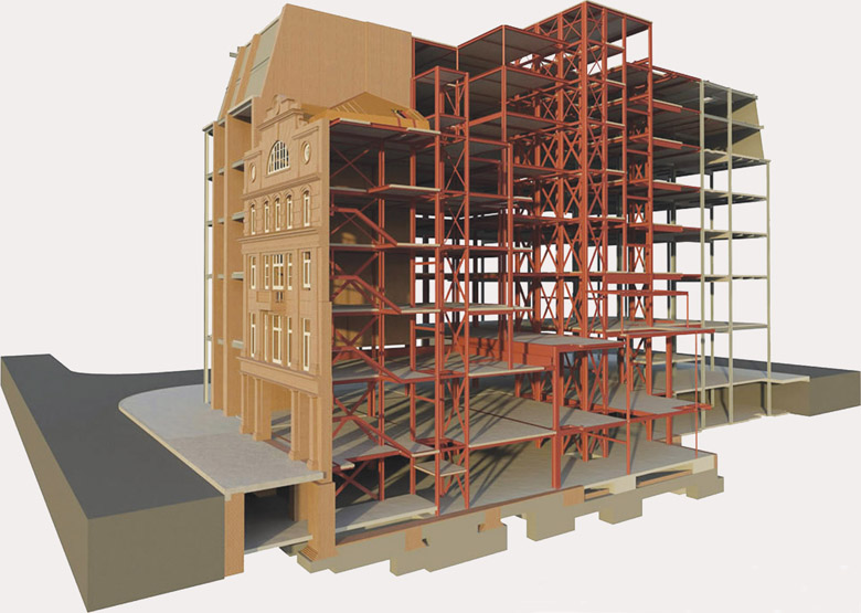
Figure 2.08: Model of steel-framed structure with retained listed facade.
Timber
A basic starting point is that any timber used should be sustainably sourced, holding an FSC or equivalent certification. Trees absorb CO2 through photosynthesis during their growth. After being cut down and fabricated, the benefit of the carbon they have captured and stored can be claimed – the so-called carbon sequestration.
In general, for simple structural timber more CO2 is captured during growth than emitted through fabrication. Disposal is key and landfilling should be avoided as noted in the point above about timber shuttering. Another area to consider is the specific preservatives and adhesives used in fabricating composite timber elements, such as glued laminated timber (GLULAM) and cross-laminated timber (CLT), which can release harmful substances including CO2.
Structural systems
The most popular structural solutions across the UK commercial building stock, including residential blocks, were selected to be analysed for this study: reinforced concrete (RC) frame, post-tensioned concrete (PT RC) frame, steel frame with metal decking, and steel frame with CLT slabs (the latter being less commonly used). The relative contribution of superstructure to the total embodied carbon of different commercial building projects SCP has worked on is substantial: 44% on average, ranging between 30 and 64%, depending on the circumstances.
The durability of all structural systems investigated has been assumed to be equivalent and to exceed 60 years. The case study buildings used were office type. Several variants have been modelled for each of the main structure types to account for different design specifications, and the embodied carbon has been calculated for each. The focus has been on the various types of superstructure, while the substructure – piled foundations – has been assumed to be the same across all options and proportionate to the dead weight of the superstructure. The live loads remain unchanged for all case studies as they are all the same building type. Images and additional guidance have been kindly provided by HTS structural engineers.
The bar graph in figure 2.09 illustrates the whole life carbon footprint of each of the variants per m2 of Gross internal (floor) area (GIA) of the building. The embodied carbon of the substructure is hatched with oblique lines while the embodied carbon of superstructures is shown in solid bars, each colour representing the overarching structural system type. The pale grey bars display carbon emissions related to the structures’ EoL. Regarding the systems featuring timber, the orange shaded rectangles with the arrow pointing down represent the carbon sequestered.
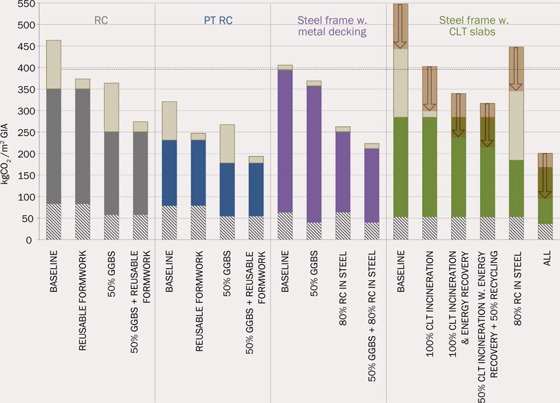
Figure 2.09: Comparative graph of the carbon emissions per m2 GIA of the different variations of the structural systems analysed.
| COST SUMMARY | RC | PTRC | Steel frame w.nbdeck | Steel frame w.CLT |
| Superstructure | 210–285 f/m2 GIA | 280–380 f/m2 GIA | 255–345 f/m2 GIA | 300–410 f/m2 GIA |
| Total | 265–355 f/m2 GIA | 350–475 f/m2 GIA | 325–445 f/m2 GIA | 380–515 f/m2 GIA |
Source: SCP Data (Athina Papakosta)
As demonstrated in figure 2.09, the EoL carbon emissions due to any sort of organic waste – either formwork for the RC and PT RC structures or CLT floor slabs – contribute a substantial share to the whole life picture. The variation in the results reveals sizeable carbon reduction potential for all types of structures against the respective baselines for basic specification. The standard RC frame has been considered as the baseline. The total whole life carbon of the different options varied between up to +18% for conventional steel frame with CLT slabs if the timber gets landfilled, and up to -58% for concrete frame with PT slabs using 50% GGBS cement replacement against the RC baseline, as shown in table 2.01.
The steel frame options are fairly high in embodied carbon due to the base assumption of 20% recycled content in steel, which results in about 1.7 times higher embodied carbon compared to the more commonly used average of 60% recycled content for steel products. 20% recycled content was selected as it represents the current UK market average for steel sections more accurately; 60% is an average across all steel products and not specifically structural steel profiles. Based on the same logic, 100% recycled content has been set as the baseline for steel bar reinforcement.
Looking at the steel frame with CLT slabs variant, it is apparent that the EoL carbon impact of timber is decisive and should be considered from the outset. Timber can be a highly sustainable material option if care is taken to avoid the considerable carbon footprint arising from its decomposition or incineration where the produced heat is not put to use.
Designing for the future – end of life, circular economy, reuse, recycling
The EoL figures presented in this case study clearly highlight the importance of considering a whole life perspective for structural systems, as opposed to the common perception that such elements have no further carbon implications beyond practical completion as they do not require any maintenance or replacement over the life cycle of a building. To create more environmentally conscious buildings, the reusability, recyclability and further potential EoL scenarios of structural elements must be incorporated into the decision-making process from an early design stage.
The adaptability of structures is also key as it determines a building’s capacity to cater for future needs. A flexible structural design is more likely to be retained in the future as it will respond well to change and so contribute to a lower overall carbon footprint. ‘Flexibility’ in this context can mean the ability to accommodate different uses. It can also mean demountable structural elements, eg precast concrete floor planks of standardised spans, or bolted instead of welded steel connections. These are useful ways to ensure adaptability and reusability within the context of resource efficiency and the circular economy. Fitness for purpose in a holistic sense, balancing durability and flexibility, should be a key driver for optimising the design.
Conclusions
The type of structural system chosen is highly influential on a building’s layout as well as on the type and quantities of materials to be used. It also has a big impact on embodied and whole life carbon. End of life needs to be considered from the outset to enable future adaptations and minimise carbon cost. Any of the structural systems examined can result in low carbon solutions if they are efficiently designed and carefully specified in terms of materials and EoL treatment. Reusing and recycling of elements is an effective carbon reduction and resource efficiency measure and constitutes the basis of circular economy.
Whole life carbon – curtain walling
This case study is based on SCP’s work on a commercial office project for Argent LLP at the King’s Cross development site in London.3 SCP was engaged at RIBA stage 2 to provide carbon analysis advice across all areas of design for the duration of the project. At stage 2, SCP provided detailed life cycle and carbon emissions analysis of the various cladding and structure options under consideration.
Facade systems can typically account for a significant proportion of a building’s embodied carbon (13–21% range; average 16%) and construction costs (17–22% range; average 19%) at practical completion.
Additionally, the specification and procurement of a building’s facade can have a long lead-time (40-plus weeks is typical). This can limit flexibility, so early discussions and decisions around low carbon facade options are important.
Aluminium, a commonly used facade material, has a highly energy-intensive production process and is responsible for around 1% of global greenhouse gas emissions. However, since the carbon intensity of aluminium can vary 20-fold (from virgin to recycled aluminium), the embodied carbon of aluminium components can be greatly reduced through some simple design and specification decisions.
The global consumption of aluminium is expected to triple or quadruple by 2050 and, while the rate of recycling can be improved (approximately 30% of aluminium in circulation is recycled), much of this demand will need to be met through carbon-intensive virgin aluminium. Within Europe, 65% of the aluminium consumed is produced outside the EU Emissions Trading System, so it is important to consider the global aluminium supply chain. Figure 2.10 maps out an illustrative example of virgin aluminium production: Bauxite (labelled 1 in figure 2.10) is extracted from a mine in Brazil and transported by road to a refinery where it is converted to alumina (2). The alumina is shipped to a plant in Norway where it is smelted into aluminium billets (3) via an electrolytic process. The billets are transported to Germany where they are extruded (4) into profiles. These are then anodised (5) in England before being fabricated (6) into curtain wall frames in Northern Ireland. Finally, the frames are delivered to the construction site in London (7).

Figure 2.10:
Illustrative supply chain for aluminium curtain wall frame.
The most significant step from a carbon perspective is the electrolytic smelting process, which uses a large amount of electricity and accounts for around 60–90% of emissions. The location of the smelting plant, and consequently the mix of energy sources of the electricity used, is therefore a key negative emissions factor. The energy mix can range from coal-dominated (80% coal in China – the world’s largest producer of virgin aluminium, representing a third of global supply) to renewable-dominated (90% hydroelectric in Latin America). The careful selection of an aluminium supplier (in terms of recycled content and energy source) can greatly reduce the embodied carbon of the purchased product. This ‘green demand’ can also provide a market signal to aluminium producers and incentivise investment in low carbon production technologies, recycling and the circular economy, thus helping to drive the decarbonisation of the aluminium sector in the long term.
The effect of some common specification and procurement choices on the embodied carbon of 1kg of aluminium is shown in figure 2.11. One of the simplest ways to reduce aluminium’s embodied carbon is to use aluminium with a higher recycled content. Compared with virgin aluminium, increasing the proportion of recycled content can reduce the embodied carbon by around 42% for medium recycled content (50% recycled), or by 75% for very high recycled content (90% recycled). Sourcing aluminium produced using renewable hydro-energy (rather than a conventional energy mix) can reduce embodied carbon by 25%.
Finally, the choice of aluminium finish will alter the embodied carbon, but this may affect the appearance. A polyester powder coated (PPC) finish can save up to about 30% embodied carbon compared with an anodised finish. Some large paint manufacturers now offer an ‘anodised look’ PPC finish, which offers much lower embodied carbon without compromising the aesthetic. The finish also affects recyclability at end of life. Anodising aluminium changes its chemistry and makes it more expensive and complex to recycle than a PPC finish. Therefore, anyone following circular economy principles would do well to avoid anodising aluminium.
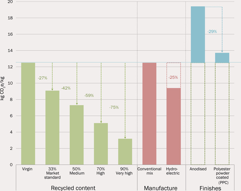
Figure 2.11: Embodied carbon of 1kg aluminium (BS EN 15978:2011, module A1-A3).
Timber/composite frames
An effective way to reduce the embodied carbon of a curtain wall frame is to move away from a fully aluminium construction to a composite aluminium and timber frame. Timber has considerably lower embodied carbon than aluminium and has the benefit of carbon sequestration during tree growth. However, it is important to note firstly that this composite material should be easy to separate, and secondly that the timber should be disposed of appropriately at end of life (recycling, reuse, or combustion for energy or heat). If the timber is sent to landfill, the subsequent methane emitted during decomposition can negate much of the carbon benefits that timber offers.

Figure 2.12:
Curtain walling types – composite aluminium timber frame (right) and aluminium (left).
Curtain wall systems – WLC analysis
The WLC per m2 of façade for the worst case scenario – fully anodised, virgin aluminium frame produced using a conventional energy mix, and including glass, gaskets, fixings, etc – is shown on the left of figure 2.13. The potential percentage reduction in WLC for each measure is shown in turn, starting with the energy source, then the aluminium frame finish, the recycled content of the aluminium, and finally the option of a composite (aluminium timber) frame. The far right of the diagram shows the WLC of the best case scenario: a composite frame with highly recycled, PPC-finished aluminium produced using renewable energy.
If the appearance of the facade cannot be changed, the WLC can still be reduced by 54% against the worst case. Our analysis shows that 10% of this reduction comes from sourcing hydro-produced aluminium, 17% from specifying a PPC finish with an anodised look instead of an anodised finish, and a further 27% is achieved by using aluminium with 90% recycled content.
If the appearance can be changed, specifying a composite aluminium timber frame provides a further 17% saving, giving a total WLC reduction of 71% against the worst case scenario.
This analysis shows that these reductions are not marginal, and that big improvements can be made through a thorough understanding of the environmental consequences of aesthetic design decisions. These can also have direct financial benefits, as PPC on aluminium with high recycled content is usually significantly cheaper than anodising predominantly virgin aluminium extrusions.
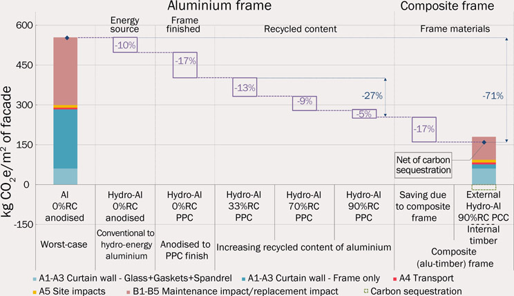
Figure 2.13: The effect of low carbon choices on the whole life carbon of a facade system.
Curtain wall systems – life cycle and other considerations
Typically, the life cycle of traditional aluminium curtain walling is limited to about 40–50 years. The principal reasons are that the seals to the double- (or triple-) glazed units fail, the finishes (particularly powder coating) deteriorate and the neoprene gaskets need replacing. Some of these failures are accentuated by the orientation and location of the building. Knowledge and consideration of the lifespan aspects of such systems should be included in design thinking from the outset. The components of any such system will deteriorate at different rates; thus a system is usually dependent on the item with the shortest life expectancy, ie the ‘weakest link’. Examining the comparative life cycles of the various components in a system such as a facade is therefore crucial to its overall life expectancy.
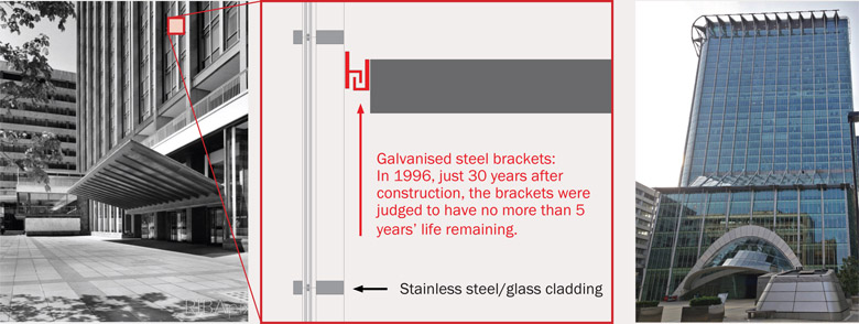
Figure 2.14:
Stainless steel/glass cladding – Britannic House, London. Illustrating that the life of a system is dependent on the weakest link.
The above example shows the original Britannic House, built in 1967 with stainless steel cladding. This had a potentially unlimited lifespan except that, crucially, the stainless steel cladding was held to the structure with galvanised fixings that needed replacing by 1996. This led to a full cladding replacement and remodelling by architects Sheppard Robson. Fortunately, the concrete frame was retained and reused.
Cladding maintenance and replacement life cycles should be considered in relation to the maintenance/replacement cycles of other systems within the building, and in relation to the activities of the occupants (eg lease cycles). Construction methodology also has an impact on life cycle. Unitised cladding systems, which are interlocking across a facade, make local change or upgrading very difficult, if not impossible. The ability to maintain and/or to dismantle a facade easily and efficiently is a low carbon characteristic. A final positive life cycle attribute is designing in the ability to recycle or even fully reuse a facade. Other factors to consider that could reduce the WLC footprint include high road transport emissions associated with heavy glazing elements; using local sources will reduce emissions and provide social benefits local to the site.
Conclusions
The most significant factors with respect to the carbon footprint of aluminium used in curtain walling are recycled content and surface finish. Most cladding manufacturers use a proportion of recycled content, but this can vary considerably – by up to as much as 80–90%. It is worth asking for this information as part of the tender process. Where the recycled content is sourced also influences the transport emissions.
Typically powder coating has lower initial carbon costs in comparison with anodising; however, finish life expectancy should also be considered when making a choice.
Anodising requires more consistent and therefore higher quality aluminium to ensure a consistent colour, whereas powder coating does not. This can affect price. Each finishing process has different energy demands and chemical impacts. The key point is to be aware of these impacts when making choices.