
Chapter 9. IP Services
This chapter discusses the evolution from circuit-switched to Internet Protocol (IP)—based packet-switched infrastructures to support the variety of IP services in use today, including IP telephony (IPT), IP television (IPTV), and virtual private networks (VPNs). IPT involves the transmission of voice, fax, and related services over IP-based packet-switched networks. IPTV systems deliver digital television service to a subscriber, using IP over a broadband connection. VPNs are a critical requirement for businesses because they distribute mission-critical and sensitive traffic to remote locations; they offer networking security and performance comparable with that available at the office.
The Evolution to IP Services
Service providers are in the midst of a gradual evolution from circuit-switched to IP-based packet-switched infrastructures. IP is attractive for two main reasons: cost savings and revenue. Carriers expect operational and infrastructure savings from deploying new IP-based services because they believe that implementing applications on IP networks will be much less expensive than running them on circuit-switched networks. In addition, every carrier is looking for new ways to enhance its service suites, which are rapidly becoming commodities.
The evolution to IP-based infrastructures means more shared networks. Because IP emphasizes logical over physical connections, IP makes it easier for multiple carriers to coexist on a single network. This encourages cooperative sharing of interconnected networks, structured as anything from sales of wholesale circuits to real-time capacity exchanges. It also means increased competition because there are reduced barriers to entry; new companies can enter the market without the huge fixed costs associated with traditional network models.
Most of the evolution so far has taken place in the transport and access parts of the network and in the development of IP infrastructure elements, such as gateways, softswitches, and the IP Multimedia Subsystem (which is discussed in Chapter 10, “Next-Generation Networks”). The market for next-generation IP application services is beginning to take shape, and IP-based application servers have been developed to deliver actual revenue-generating services for carriers.
The problem is that IP has been positioned as a magical potion that will cure everything, and the industry has suffered from too much hype and wishful thinking. Equipment and service providers have been guilty of promoting such thinking, claiming that their products can enable multiple new services without clearly identifying just what those new services will be. While there are indeed very good reasons to transition to IP, it is important to be realistic and pragmatic about them. The migration to IP is not without risk. In terms of the IP application services market, two key questions need to be answered: Will the quality of the real-time services over IP be good enough in the next few years to drive carriers and customers to switch? To what extent will enterprises take advantage of their existing IP infrastructure and data communications expertise to implement their own services, thus avoiding additional service provider charges?
Traditional Internet applications, such as e-mail, Telnet, FTP, and the World Wide Web, are referred to as elastic applications because they are tolerant of network delays and packet losses. Unlike those applications, advanced real-time applications are highly sensitive to timely data delivery. Quality of service (QoS) is the most important obstacle for the Internet and IP networks to overcome, especially in light of the growing use of voice and video. As QoS emerges within the Internet, the ability to differentiate services will result in differentiated pricing. QoS capabilities will allow revenue-generating service levels to be implemented and service-level agreements (SLAs) to be negotiated.
The ability to control and manage a network effectively will allow the creation of value-added services and packages. Providing value-added IP services implies increased attention to tools and equipment that help service providers succeed. These include software that gives service providers greater network control and visibility; intrusion prevention systems that support always-on stateful inspection (i.e., a form of stateful inspection that provides cumulative data against which subsequent communication attempts can be evaluated and acted on in real-time) and deep packet analysis capabilities; software that can deliver flexible bandwidth; tools that offer granular analysis of bandwidth consumption by customers; and tools that enable creative solutions that reduce costs, such as the robots from CityNet Telecommunications (www.citynettelecom.com) that string fiber through sewers at a fraction of the cost of digging up city streets to lay the fiber.
Value-added IP services allow carriers greater differentiation from their competitors. Evolving next-generation IP services include IP virtual private networks (VPNs), IP telephony (IPT) and Voice over IP (VoIP), IP centrex and IP call centers, application hosting, mobility management/follow-me services, unified messaging, instant messaging (IM), presence management, Video over IP, IP television (IPTV), and different types of conferencing, including audioconferencing, videoconferencing, and Web/data conferencing. As carriers consolidate and wireless broadband networks are deployed, a major challenge will be developing viable business models to market, bill, provision, and provide excellent customer care for all these services.
Many incumbent carriers are choosing to initially implement IP-based services on an overlay network. Carriers that take this approach do not have to replace circuit-switched network elements, which usually have minimal ongoing operational expenses. In an overlay network scenario, the packet-switched network is isolated from the circuit-switched network, and the two are connected via a gateway.
IPT
IPT has been drawing a lot of attention in the past couple years, and terminology in this area is confusing, with VoIP being the most common expression, even though there are in fact technical differences between IPT (the umbrella term), VoIP (IPT over private IP networks), and Internet telephony (voice over the Internet). The following sections cover the types of applications anticipated for IPT as well as what network elements are required in order to make IPT work and provide similar capabilities to what we are used to from the PSTN.
Although IPT has a very important place, it is not yet taking over the traditional circuit-switched approach to accommodating voice telephony. The truly exciting future of IPT, or VoIP, lies in advanced and interesting new applications, an environment where voice is but one of the information streams comprising a rich media application. While such applications are being developed, there are other compelling reasons to adopt IPT, including the reduction of toll and international calling charges, which makes a strong argument for many businesses and consumers. The network-specific cost for VoIP on dedicated networks is quite a bit lower than the cost of calls on circuit-switched networks, not to mention the benefit an average residential user, with family members and friends scattered around the globe, can gain by avoiding the normally sky-high charges associated with international calling. Many analysts expect that sales of VoIP equipment will grow rapidly in the coming months and years.
People use several IP-related terms interchangeably. However, according to the International Telecommunication Union (ITU; www.itu.int), there are distinctions between the following terms:
- IPT—The transmission of voice, fax, and related services over packet-switched IP-based networks. Internet telephony and VoIP are specific subsets of IPT.
- Internet telephony—Telephony in which the principal transmission network is the public Internet. Internet telephony is commonly referred to as Voice over the Net, Internet phone, and net telephony, with appropriate modifications to refer to fax as well, such as Internet fax.
- VoIP—IPT in which the principal transmission network or networks are private, managed IP-based networks.
This chapter generally uses the encompassing term IPT.
With leading telecommunications carriers and cable companies unveiling major VoIP initiatives, consumers and businesses will be hearing a great deal more about VoIP in the near future. Despite the long road ahead, consumer and business migration to VoIP is on the verge of moving out of the early adoption phase and into the mainstream, and the hope is that widespread (although not ubiquitous) VoIP use will finally take off by 2007. It appears that some 20% of businesses have already adopted VoIP technology. Interestingly, companies are citing benefits other than reduced costs as the reasons for switching to VoIP. The biggest reasons mentioned have to do with strategic investments, integration with existing IP VPNs, employee mobility, and increased productivity. Reduced costs alone are not likely to propel IPT or VoIP to the pedestal envisioned by its proponents.
The IPT Evolution
We know that IPT is here for several reasons. First, we can do it effectively, and greater processing power (following Moore’s Law) applied to signal processing along with lower costs makes VoIP attractive. Second, as discussed later in this chapter, standards for VoIP have made progress. Third, IP has become pervasive: It is easier now for both businesses and consumers to enter the IPT realm. Finally, the marketplace is now home to many commercial entries.
Moore’s Law refers to a prediction made in 1965 by Gordon Moore, cofounder of Intel. Moore said that the number of transistors occupying a square inch of integrated circuit material had doubled each year since the invention of the integrated circuit, and he predicted that this multiplication of circuitry would continue. For the most part, the prediction held true until the late 1970s, when the time span of a year increased to about 18 months. Today Moore’s Law is commonly used as an expression to state that the power of microprocessor technology doubles and its cost of production halves every 18 months.
Many variations of phones, gateways, IP PBXs, and open-source PBXs are now available to both consumers and enterprises. Several key milestones have been reached. There has been a surge of Session Initiation Protocol (SIP) support and offerings for SIP-based enterprise communications, and SIP products are now widely available. Avaya (www.avaya.com), Lucent (www.lucent.com), and NEC (www.nec.com) have announced SIP enterprise product lines. Microsoft (www.microsoft.com), IBM (www.ibm.com), Novell (www.novell.com), and Sun Microsystems (www.sun.com) are all moving to SIP for their enterprise collaboration tools. Cisco (www.cisco.com) has announced the migration of its proprietary call manager technology to SIP. (SIP is discussed in detail later in this chapter.)
Most enterprises today are not using or considering IPT services, but many are using or considering migrating to Multiprotocol Label Switching (MPLS), in part because combining voice, video, and data can finally justify the cost of MPLS. Most organizations are currently using predominantly ATM or Frame Relay, with some IP VPNs here and there. The cost differential between Frame Relay or ATM and MPLS is less than 10%. But if voice and video are added, it can reach 25% and justify the move to both MPLS and IPT.
However, many unresolved issues challenge widespread deployment of IPT. For example, the connection to emergency service access systems is problematic. Callers may not know that the IPT phone they are using is not connected to emergency services, creating potentially fatal problems. Surveillance is another public safety issue. Data encryption schemes are making it more difficult for law enforcement agencies to conduct surveillance because they may not be able to listen to IPT calls in the manner that has become standard in the circuit-switched world. For example, if police officers have to decrypt an IPT call instead of listening in real-time, they may have to wait three weeks after the call took place in order to use it as a basis for arrest.
IPT is being deployed today on a trial basis. The main application is currently LAN-to-LAN or cross-enterprise solutions, typically using matched gateways linked by private lines. The cost justifications are roughly split between toll bypass or WAN savings and cost reductions in moves, adds, and changes. Justifying the move to IPT therefore is largely centered initially around cost justification. Besides the benefit of toll bypass, IPT offers a reduction in the cost associated with staff; increased efficiencies due to using the existing IP data networks to also carry voice; less expensive moves, adds, and changes; and applications benefits, such as the ability to combine the Web and computer telephony integration applications and to provide a universal desktop device.
Regulatory Issues Surrounding IPT
IPT services are not seeing large growth yet, but they are definitely affecting decisions about WAN architectures. Ultimately, whether and how quickly we move to IPT is not just a question of technical solutions; the regulatory environment may determine whether these services flourish in the long run.
In an interview he did with the San Jose Mercury News on December 31, 2003, then-Chairman of the U.S. Federal Communications Commission (FCC; www.fcc.gov) Michael Powell said, “To be a phone company you don’t have to weave tightly the voice service into the infrastructure. You can ride it on top of the infrastructure. So if you’re a Vonage, you own no infrastructure, you own no trucks, you roll to no one’s house. They turn voice into an application and shoot it across one of these platforms and suddenly you’re in business. And that’s why if you’re the music industry you’re scared. And if you’re the television studio, movie industry, you’re scared. And if you’re an incumbent infrastructure carrier, you’d better be scared because this application separation is the most important paradigm shift in the history of communications and will change things forever. I have no problem if a big and venerable company no longer exists tomorrow, as long as that value is transferred somewhere else in the economy.” These are interesting words to contemplate as we try to predict what the regulatory approach toward IP communications will be, and the approach will no doubt vary around the world.
The area of international regulation has seen increasing activity, mostly from the United Nations (UN) and the ITU (which has regulated spectrum and telephony for decades and was placed under the auspices of the UN). For some time, the ITU has been considering what role it should take in relationship to the Internet, a medium that grew up completely independent of the ITU and where most activists see no positive role for the ITU. Another UN/ITU activity, the World Summit on the Information Society, has established a working group on Internet governance to look into these issues. A new set of European Union (EU) directives will significantly affect the licensing requirements of IPT in Europe. The European Commission (EC) is the driving force for determining whether IPT should be treated and licensed as conventional telephony. Member states are allowed some discretion as to the implementation of the EC’s directives, but the EC does not issue telephony licenses; that is left to the member states. However, many issues still require resolution, including wire tapping, interconnection and regulatory fees, universal service contributions, and access to a system that allocates telephone numbers and a directory system.
European legislators and regulators have not finished the debate on how to treat IPT and are seeking suggestions from the industry on new developments and technical solutions. For instance, regarding wire tapping, Europeans are closely observing any new developments in the United States. In particular, at the FCC, VoIP is by default treated as an information service and currently does not contribute to the Universal Service Fund.
The next generation of IPT will offer strategic value to the enterprise by combining presence-aware communications applications with extended converged networks. This is possible thanks to two technological advances: first, the ability of extended converged IP networks to unify voice, data, wireline, and wireless domains, supporting applications that unify the end users’ communications experience, and second, the continued growth and processing power of bandwidth and storage. As bandwidth and storage become less expensive and more abundant, there will be better and more choices for software services and content.
The Next Generation of IPT
The IPT evolution has so far been through three phases:
- Point-to-point communications over IP networks—These communications are largely based on the use of ITU H.323 standards, a philosophy of having intelligence everywhere.
- Master/slave architectures—These architectures rely on standards such as Megaco and Media Gateway Control Protocol (MGCP). This approach is an effective way to implement rich feature sets in dumb endpoints.
- The integration of communications media with the Internet—This strategy involves intelligent endpoints and a dumb network. The relevant standards include SIP and SIP for Instant Messaging and Presence Leveraging Extensions (SIMPLE).
Next-generation IPT applications are most distinguished by two specific applications: (1) synchronous communications that streamline and enrich business processes and (2) presence awareness that allows one to see who is available for collaboration and how to reach them. Key IPT productivity benefits for the field force include increased efficiencies among service employees, shortened reaction times, improved service quality, and an increase in the number of customer contacts. For the sales force, the benefits of IPT include a reduction in the number of client appointments needed, lower service costs, shortened proposal and negotiation processes, and improved transparency of the sales processes. For the supply chain, the key productivity benefits include reduction of inventory levels, improved data quality, fewer disruptions in downstream processes due to logistical errors, and lower total logistical costs.
The IPT Network
As shown in Figure 9.1, the IPT network taxonomy has three major layers:
- Media layer—In this layer, on the bearer platform, media is processed, including the media transport, QoS, and items such as tones and announcements. Two bearer platforms communicate with one another over media transport, and this is where TDM, Frame Relay, ATM, and MPLS apply.
- Signaling layer—Signal processing, signaling conversion, resource management, and bearer control occur on this layer, on the signaling platform. Signaling platforms talk with one another by using a signaling technique. This is where H.323, SIP, and other call control protocols apply.
- Application layer—This layer, referred to as the application platform, is home to call intelligence, and it is where service creation and execution as well as provisioning management occur. Application platforms talk to one another with application-specific interapplication protocols.
Figure 9.1 The IPT network taxonomy
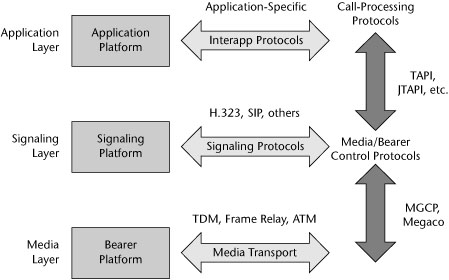
Between the bearer and signaling platforms are media/bearer control protocols. This is the realm of MGCP and Megaco. Between the signaling and application layers are call-processing protocols such as Telephony Applications Programming Interface (TAPI) and Java TAPI (JTAPI).
In terms of the transport infrastructure, a number of packet network alternatives can be used, and the full range of packet-switching techniques—including IP, Frame Relay, ATM, MPLS, and GMPLS, as well as Ethernet, Voice over Wireless LAN (VoWLAN), Voice over DSL (VoDSL), and Voice over Cable—can act as the transport infrastructure.
Until recently, the IPT business model has been much like the traditional circuit-switched world, with each vendor supplying its own platform, handset, gateway, call-processing, and end-user feature sets. Convergence for the early IPT player involved converging voice onto the data network and selling telephony to the IT buyer. To this day, one of the greatest challenges is for traditional voice vendors to learn to sell what the data people buy.
Many in the industry view long-distance as the first major market disruption in the transition from TDM to IP and handsets as the second. Initially, IPT had the most disruptive effect on carriers’ transmission networks. This promoted a competitive triangle between the handset, the platform, and the network. Industry analysts predict that the next few years will see battle between these three industries as each attempts to commoditize the other two.
The IPT Network Architecture
The first requirement for an IPT network is an IP local exchange or media gateway (also referred to as a VoIP gateway). Gateways are carrier-class products that reside in the service provider network. They provide PBX-like telephony service to multiple business and telecommuting customers as well as basic telephony services for consumers. Another requirement is the softswitch (also called a call server or call agent) for call-processing functions and administrative software. End-user services are delivered by IP phones and other devices. Finally, IP-based voice enterprise systems include IP PBXs, open-source PBXs, and service provider solutions. Figure 9.2 shows an example of the IPT network architecture, and the following sections describe the components.
Figure 9.2 IPT network architecture
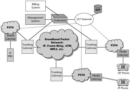
Media Gateways
Gateways provide seamless interoperability between circuit-switching and packet-switching network domains. They interconnect with the Signaling System 7 (SS7) network and handle IP services. They support a variety of telephony signaling protocols, such as H.323, Megaco (H.248) and MGCP, and SIP. They support Class 4 (i.e., toll) switches and Class 5 switches (as in local exchange services). They operate in the classic public network environment, where call control is separate from media flow. They support a variety of traffic, data, voice, fax, multimedia, and so on over a data backbone.
Softswitches
In enhanced applications such as network conferencing, network interactive voice response, fax serving, network voicemail, and directory services, a softswitch controls the voice or data traffic path by signaling between the media gateways that transport the traffic. The gateway provides the connection between an IP or another packet-based network (such as ATM or MPLS) and the traditional circuit-switched network, acting as a multiprotocol cross-connect. The softswitch ensures that a call’s or connection’s underlying signaling information gets communicated between gateways. The signaling information may include automatic number identifiers, billing data, or other call triggers.
Softswitches must communicate with packet switches, VoIP gateways, media gateways, and SS7 networks by using standardized protocols. A number of different technical specifications, protocols, and standards are involved in delivering these services and the desired end functions. As discussed in more detail later in this chapter, they include H.323, Megaco and MGCP, SIP, Real-Time Transport Protocol (RTP), Real-Time Transport Control Protocol (RTCP), RTCP Reporting Extension (RTCP XR), and Secure Real-Time Transport Protocol (SRTP).
IP Devices
A number of IP devices are available:
- Legacy support—Simple terminal adapters are available for standard telephones.
- IP hard phones—These are IP phones that look and work just like a traditional multiline business display phone. They plug in to an Ethernet RJ-45 jack. Typically, they’re proprietary and part of a vendor’s platform. Their original prices were similar to PBX phones, around US$300 and up, but are now down to less than US$100. Emerging IP phone-on-a-chip technologies promise dramatically lower prices in the near future.
- IP soft phones—IP soft phones are software that runs on a user’s PC and graphically resembles a phone. The key advantage of this approach is its low price. IP soft phones are gaining acceptance because applications such as presence management and IM are much better on a PC than on other devices. The disadvantages lie in the fact that an IP soft phone relies on the PC sound card, which can create problems with the volume level when switching between the soft phone and other applications that use the PC sound card. However, products such as the Clarisys USB handset (www.clarisys.com) overcome these problems. This device replaces the headset, rings audibly, includes a speakerphone, and, as a USB device, avoids the PC sound card.
- IP Web phones—These devices combine a complete analog phone device and a diskless processor, providing an e-mail browser and a variety of organizer applications such as a call list and directory manager, a notepad, and a calendar.
- SIP phones—SIP has the potential to realize the ultimate IPT dream: low cost, feature-rich headsets from third-party phone vendors. SIP for VoIP phones is mature and solid, with at least six models passing the test. Major platform vendors continue to rely on propriety protocols for both their platforms and their handset features. This suggests that despite talk of support for SIP, complete openness and interoperability have yet to be achieved. However, vendors can test the interoperability of their SIP implementations with other vendors three times per year at the SIP Forum SIP IT events (www.sipforum.org).
- Mobile IP devices—This category includes 3G handsets, Wi-Fi SIP phones, PDAs equipped to handle VoIP, and game platforms.
In addition, the emerging generation of intelligent wearables, automobiles, smart appliances, smart rooms, and ultimately implants will all add to the expanding universe of IP devices.
IP-Based Voice Enterprise Systems
There are three main approaches to IP-based voice enterprise systems: IP PBXs, open-source PBXs, and service provider solutions, which include IP centrex, hosted PBX, and virtual PBX services. IP PBX and IP centrex offer network management advantages over legacy PBX solutions.
IP PBXs What can an IP PBX environment do that a traditional PBX can’t? IP PBXs boast dozens of new applications, ushering in a new era of human communications, productivity, and mobility. These enhanced and advanced applications are a very hot area, representing the potential for incredible revenue. Significant progress has been made in several key applications areas: unified messaging, which is defined today as the merger of voicemail, e-mail, and fax; conferencing applications; collaboration applications; presence awareness; multimedia packages; mobility features; and extensible SIP support.
The most notable trends include the fact that video is coming to the desktop. Point-to-point or multiparty video is being offered by the majority of leading IP PBX vendors, and the cost per desktop is now generally under US$200. Document collaboration now allows document sharing to be more than a one-way display of PowerPoint slides. Impressive new capabilities from leading vendors include real-time coediting and collaborative working on the same document. In addition, exciting new mobility capabilities are being developed, ranging from a simple SMS gateway that lets local IM users send short messages directly to coworkers’ mobile phones and pagers to sophisticated call control features with which remote and traveling workers can easily place calls and set up complex conferences.
Not every product will contain each and every one of the key collaboration and conferencing features, but the following is a comprehensive list of the types of features that are available: soft phone support; the use of presence, be it dynamic or static; mobility features; conferencing, either scheduled or ad hoc; search capabilities; contacts and database access and integration; video (either point-to-point or multipoint); call control of external devices as well as call control filters that allow you to find me and follow me; recent call history; the ability to sort or quick-dial; IM, with chat or multiparty IM; document viewing and presentation; document collaboration and coediting; and whiteboarding and Web cobrowsing. As this list shows, a significant number of productivity-enhancing features are becoming available and adding a new dimension of value to IP PBX functionality.
The key unified messaging features include redundant voicemail servers; text-to-speech readout of e-mail (in multiple languages); automatic speech recognition; an inbox that shows the caller by automatic number identification and/or name; voicemail and e-mail that indicate the message duration; the ability to reply to and forward voicemail and e-mail; the ability to add other attachments; the ability to send voicemail and e-mail via distribution lists; telephone user interface–based retrieval of voicemail or e-mail; callout of system voicemail delivery; voicemail notification options; scheduled delivery of voicemails; the ability to dial back from the inbox interfaces; and mobility features.
Early marketing efforts for IPT systems focused on a variety of cost-saving and productivity benefits, with little emphasis on the advantages of a more flexible system design. However, it is becoming evident that these two benefits are best realized by taking advantage of a third aspect of IP PBXs: their inherent ability to provide a more modular and survivable configuration compared with traditional circuit-switched TDM PBXs. Customers with multiple premises can configure an IP PBX to operate seamlessly across two or more locations at a lower cost and with greater performance capabilities than a network of standalone systems would offer.
One of the major factors in the accelerated migration to the new IP-based platforms is their ability to replace multiple standalone systems, such as key telephone systems, hybrids, or standard PBXs, with a single IP PBX system that uses survivable remote equipment to create a dispersed architecture. The ability to leverage an existing data network infrastructure for both call control signaling and voice communications transmission is a relatively recent enhancement to IPT. However, because IPT architectures are based on LAN/WAN connections, the enterprise must ensure that backup systems are in place in the event of a loss of LAN/WAN connectivity.
Several IPT design options are available to customers who favor a single-system approach to serve multiple premises. These options range from the simplicity of remote, standalone IP telephones to standalone servers coupled with fully provisioned distributed port carrier cabinets that function as media gateways between traditional station trunk connections and the LAN/WAN. The customer money saved using a distributed or dispersed IPT system solution for multiple-premises communications requirements can be substantial, and a single-system design can also provide significantly enhanced performance and operating benefits. Using an IP PBX system design that supports multiple locations allows advanced features such as station user roaming and automatic call distribution to be accessed and implemented by system subscribers, regardless of their physical location. This contributes to the enhanced performance potential of the single distributed system solution with local survivability options.
Open-Source PBXs The theory behind open source is that too many cooks actually improve the broth. Widespread peer review finds and fixes bugs faster than the efforts of a smaller, albeit dedicated, project team. The result is often more robust software, lower support costs, and more rapid innovation. Of course, this challenges the established IP PBX pricing model while facilitating standards-based cooperation. However, customer concerns about product schedules and quality detract from trust in the open-source model.
Service Provider VoIP Solutions The three major approaches to service provider VoIP solutions are IP centrex, hosted PBX, and virtual PBX services, such as provider-managed call servers, application servers, and media gateways.
The main driver of service provider VoIP solutions is reducing the enterprise administration and reducing capital expenditures. Voice quality is often comparable to that in the PSTN. But the greatest benefit is the cost-efficient bundling of voice, Internet access, and enhanced features, including an auto-attendant, a Web-based dashboard for each user and administrator, integrated messaging (e.g., voicemail as e-mail file attachments), redirection to other phones, and simultaneous ringing of up to 10 phones.
Standards for IP Voice
Before we talk about the standards for IP voice, we need to discuss the characteristics of voice traffic. First of all, voice traffic is an isochronous traffic flow, meaning it involves real-time communications that are delay sensitive as well as loss sensitive. Voice has a low bandwidth requirement, but as a tradeoff, it requires very high QoS.
Digital Voice Technologies
A number of digital voice technologies are enabling IP voice as we know it today. The primary component is the codec (coder-decoder), which is used to digitize the voice stream. Two broad categories of codecs are used:
- Waveform coders—Waveform coders directly encode speech in an efficient way by exploiting temporal and/or spectral characteristics. There are several categories of waveform coders. The first is time domain, or predictive, coders, and these include the well-known standards G.711, known as Pulse Code Modulation (PCM; µ-Law in the North American and Japanese standards, using 56Kbps, and A-Law for those following the ITU standards, at 64Kbps), and G.726, known as Adaptive Differential PCM (ADPCM), which encodes voice at a reduced rate of 32Kbps, 24Kbps, or 16Kbps. Two other types of waveform coders are G.722 subband coders and transform coders, which are used to convert between different digitizing techniques.
- Source coders, or vocoders—Vocoders estimate and efficiently encode a parametric representation of speech. The standards under this category include G.728, which is also known as Low-Delay Code-Excited Linear Prediction (Low-Delay CELP) and supports digital voice at 16Kbps; G.729, known as Conjugate Structure Algebraic CELP, which reduces voice down to 8Kbps; and G.723.1, known as Multipulse Maximum Likelihood Quantization, which carries voice at 6.4Kbps.
Another element of digital voice technologies is echo cancellers, which are used to eliminate echoes. The voice echo path is like an electrical circuit: If a break or a cancellation is made anywhere in the circuit, an echo canceller can eliminate the echo. The easiest place to make the break is with a canceller looking into the local analog/digital telephony network. The echo canceller at the local device cancels local echoes from the hybrid reflection, the echo canceller at the other end of the call eliminates the echoes you hear, and vice versa.
The last part of digital voice technologies is noise generation. As it turns out, silence is not always golden. When speech stops, we generate comfort noise to help assure people that the “circuit” is still live, that the call hasn’t dropped. The simple techniques involve playing white or pink noise or replaying the last receiver packet over and over. More sophisticated techniques include options in which the transmitter measures the local noise environment. The transmitter then sends a special comfort noise packet as the last packet before silence. The receiver generates noise based on the comfort noise packet. One of the major issues in carrying voice in a packet form, be it IP, Frame Relay, ATM, or MPLS, is delay, which is discussed in the following section.
Delay, Jitter Buffers, and Error Concealment
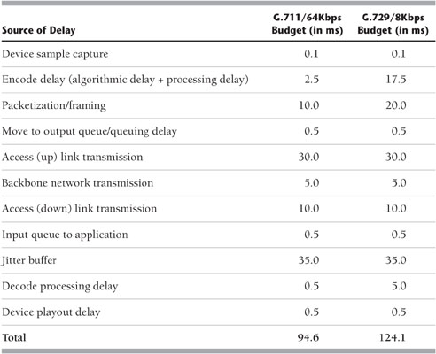
Table 9.1 shows some of the myriad sources of delay associated with VoIP. The two columns at the right are based on different codec standards. As you can see, the device sample capture introduces a bit of delay, followed by encoding delay, packetizing and framing delay, queuing delay, access uplink and downlink as well as transmission over the backbone, and various jitters that might be associated with the transmission, the decoding process, and ultimately, the playout process. The budget that results is fairly high. In G.711 at 64Kbps, the total delay is 94.6 milliseconds, while with G.729 at 8Kbps, the total delay is 124.1 milliseconds. That’s very large, especially when you consider the recommended standards for maximum delay. The ITU-T, for purposes of voice, recommends a maximum delay of 100 milliseconds end to end, with a preference, of course, for much less.
Table 9.1 Standards for IP Voice Delay
Delay is very important in real-time communications. For instance, for video, the ITU-T recommendation is 80 milliseconds maximum end-to-end delay. And when we get into some of the interactive applications such as teleimmersion or videogames, the tolerance for delay is only 30 to 50 milliseconds maximum end to end. There is a lot to consider in adequately addressing the QoS for voice from the standpoint of delay, both end to end and jitter.
As mentioned earlier in this chapter, speech is inherently isochronous. It occurs in real-time, requires a fixed amount of bandwidth, and is not very tolerant of delays or losses. Transmitters emit packets at fixed intervals, but packet networks have queues. As a result, the receivers see interarrival jitter. What do we do about this? The solution is jitter buffers. There are two varieties: fixed jitter buffers and adaptive jitter buffers. Fixed jitter buffers work as follows: A playout point is set to some fixed number of packets in the future, and the hope is that no packets arrive later than the playout point. Late arrival equals lost packets, so there is a delicate tradeoff between delay-induced impairment and loss-induced impairment. Fixed jitter buffers are useful when delay doesn’t matter, as with Internet radio, or with nonstop sources, such as fax. With adaptive jitter buffers, the ideal is to converge to minimal delay with zero loss. You need breathing room to move the playout point to address talk spurt boundaries or silence. Adaptive jitter buffers can do fancy audio processing, such as speeding up or slowing down the rate. They rely on algorithms that adapt the playout point close to measured jitter, and if loss occurs, they back off.
Another issue we have to deal with is error concealment. The techniques for this depend on the codec standards used. With waveform coders, the technique is to replay the previous packet, to interpolate, and to predict. With the CELP coders, coefficients are used to predict the gain, pitch, and so on of the missing packet. There are also some advanced adaptation techniques, such as forward error correction (FEC), in which extra packets with FEC are sent over some number of the packets. As another example, with layered coders, you send higher- or lower-fidelity or different encodings on different streams. Receivers then subscribe to appropriate layers. This is especially valuable for multicast.
Media Transport Requirements
Media transport requirements include identification of the payload, the type of codec used, the framing used, timing reconstruction, when to play out each packet within a stream, and how to synchronize multiple streams. Note that an external reference clock is needed to correlate time stamps of different RTP streams. Another requirement is sequencing—that is, how to play out in the correct order and how to detect losses.
The media transport functions include moving bits, which is accomplished with RTP and SRTP. Feedback and statistics need to be provided as well, and this is accomplished using RTCP as well as the emerging standard RTCP XR, which is a reporting extension being developed by the IETF’s AVT (Audio/Video Transport) working group.
These are the main transport protocols:
- RTP—RTP, specified in RFC 3550, is a transport protocol for real-time applications. It is used by all VoIP signaling protocols, and it is based on User Datagram Protocol (UDP). RTP provides media transport functions as well as additional features. It is multicast friendly and easy to encrypt, it provides QoS feedback with RTCP, and it requires minimal session control.
- RTCP—RTCP is based on the periodic transmission of control packets to all participants in the session, using the same distribution mechanism as the data packets. RTCP provides feedback on the quality of the data distribution. This is an integral part of RTCP’s role as a transport protocol and is related to the flow and congestion control functions of other transport protocols.
- SRTP—There is considerable interest in the use of SRTP, a relatively new protocol, to prevent eavesdropping on VoIP calls. SRTP permits the voice packet payload to be encrypted. It also allows other protocol messages, such as RTCP messages, to be protected. Encryption protects privacy. However, diagnostic troubleshooting tools cannot analyze encrypted voice payload. That’s where RTCP Reporting Extension (RTCP XR) comes in. It allows information hidden by SRTP to be extracted directly from the digital signal processing software, IP phones, and gateways and reported directly in the RTCP XR message. Of course, this assumes that the RTCP XR messages themselves are not encrypted.
- The advantages of SRTP are that it provides both privacy via encryption and authentication via message integrity checking. It uses very little bandwidth for overhead, and it uses modern and strong cryptology suites, such as Advanced Encryption Standard (AES) countermode for encryption and Keyed Hashing for Message Authentication for message integrity.
IPT QoS
QoS is managed unfairness because some users purposely get better service than others. As discussed further in Chapter 10, QoS is needed to address the stringent delay requirements of voice traffic.
Several techniques, including the following, can be used to improve various aspects of a network’s QoS:
- Random Early Detection (RED)—RED is a queue management algorithm and a congestion avoidence algorithm. RED monitors the average queue size and drops packets based on statistical probabilities. If the buffer is almost empty, all incoming packets are accepted. As the queue grows, the probability for dropping an incoming packet grows, too. On a shared voice/data queue, RED does not prevent large delay and jitter for voice. RED is primarily effective for avoiding congestion, and it works best for congestion-responsive flows such as TCP. But voice has constant bit rate and, hence, is not usually responsive, and it uses UDP. So although RED is a good mechanism for many network applications, it is not the most effective for IP voice.
- Weighted Fair Queuing (WFQ)—With WFQ, each flow gets a share of the server link bandwidth in proportion to its weight. Per-packet delay guarantee in a WFQ scheduler depends on the accuracy of the WFQ implementation.
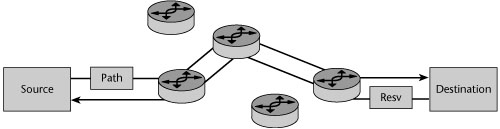
- IntServ RSVP architecture—As discussed in Chapter 10, RSVP is the primary specification for handling multimedia traffic over IP subnets (see Figure 9.3). RSVP messages are carried over IP/UDP. RSVP enhances connectionless best-effort service by providing QoS requests and guarantees. There are two main classes of service: RFC 2211 specifies control-load or best-effort service, and RFC 2212 is the guaranteed class of service (CoS), offering bandwidth and delay guarantees. RSVP relies on a router-to-router signaling scheme, which allows IP applications to request priority, delay, and bandwidth guarantees. The connection is established link by link and is denied if a router cannot accept the request. Signaling is distinct from routing. Transparent operation across non-RSVP routers is possible. RSVP supports shared and distinct reservations, applies to unicast and multicast applications, and is simplex and receiver oriented. RSVP is well suited for real-time applications and delay-sensitive traffic. However, it does not scale well in large networks, so it is not used much in WANs.
Figure 9.3 VoIP QoS: IntServ RSVP
- IP precedence—IP precedence is the poor-man’s approach to QoS. The IP precedence or DiffServ Code Point (DSCP; discussed in detail in Chapter 8, “The Internet and IP Infrastructures”) is set higher on voice packets. This puts them in a different queue, resulting in isolation from best-effort traffic. It can be done by the endpoint, by a proxy, or in routers through heuristics. IP precedence scales better than RSVP, and it keeps QoS control local. It pushes the work to the edges of the boundaries and can provide QoS by either customer or network. However, it has no admission control, so too much high-precedence traffic can still swamp the network.
- DiffServ—DiffServ employs a small, well-defined set of building blocks from which a variety of services can be built. Although DiffServ evolved from the IntServ architecture, DiffServ is a prioritization model with preferential allocation of resources based on traffic classification. DiffServ uses the DSCP to carry information about IP packet service requirements. It classifies traffic by marking IP headers at ingress to the network with flags corresponding to a small number of per-hop behaviors. In other words, queues get different treatments in terms of priority, share of bandwidth, and probability of discard. The DiffServ architecture assumes a relatively small number of feasible queue-scheduling algorithms for high link speeds. It also assumes a large number of individual flows, with many different rules, often being policy driven. The nodes at the edge of the boundaries do the hard work: They group packets explicitly by the per-hop behavior they are to receive (the queue service, the classification, and the conditioning and policing of those packets). The nodes in the middle of a cloud only have to deal with traffic aggregates. QoS is managed by local rules within the cloud, and QoS information exchange is limited to boundaries. It is bilateral, not multilateral, and it is not necessarily symmetric. Inter–service provider DiffServ and end-to-end Internet QoS need further standardization and commercial arrangements.
- Compressed Real-Time Transport Protocol (CRTP)—CRTP is basically RTP compression. Normally, the IP header is 20 bytes, the UDP header is another 8 bytes, and the RTP header is 12 bytes, resulting in a 40-byte header. CRTP can reduce the header to 2 to 4 bytes, which is really useful on slow links.
- Multi-Class Multi-Link (MCML) PPP—The idea with MCML PPP is that single-packet latency is unacceptable on slow links. A 1,500-byte message transfer unit takes 215 milliseconds to transmit on a 56Kbps link, which is significantly more than the recommended delay. MCML PPP allows multiple fragment streams on a multilink PPP session. It sets the fragment size to match the delay budget of the link (e.g., 128 bytes equals 18 milliseconds). Small voice packets are interleaved between the fragments of big packets by applying WFQ at the fragment level.
VoIP Call-Signaling Protocols
Three major VoIP protocols are used in call signaling. The first standard applied to support interoperability between VoIP systems was the ITU-T’s H.323. While it has the advantage of being a mature standard, there are some negatives associated with it, including its complexity, its tuning for PC conferencing rather than telephony, its very bad scaling properties, and its difficulty working over firewalls. The second protocol that came into play is MGCP, which advocates a centralized control architecture. It is fairly simple: It models current PSTN call control architecture but requires high-reliability and high-availability call servers. The third protocol is SIP, which advocates a decentralized control architecture. SIP is transaction based, which means it is a good match for what’s called the stupid network paradigm, where it is relatively easy to build in scalability and reliability and there are built-in security mechanisms.
H.323
H.323 is a protocol suite defined by the ITU-T for voice transmission over the Internet. First published in 1996, the latest version of H.323, Version 5, was completed in 2003. In addition to voice applications, H.323 provides mechanisms for video communication and data collaboration. H.323 defines a centralized architecture for creating multimedia applications that use VoIP, and it is an umbrella specification that includes various other ITU standards.
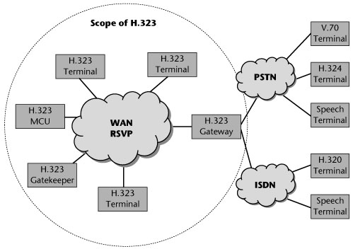
The H.323 architecture includes the following components (see Figure 9.4):
- Terminals—A terminal is the end device of every connection. It provides real-time two-way communications with another H.323 terminal, gateway, or MCU. This communication consists of speech, speech and data, speech and video, or a combination of speech, data, and video.
- Gateways—Gateways establish the connections between the terminals in the H.323 network and the terminals that belong to networks with different protocol stacks, such as the traditional PSTN network, SIP, or Megaco endpoints.
- Gatekeepers—Gatekeepers are responsible for translating between telephone numbers and IP addresses. They also manage the bandwidth and provide mechanisms for terminal registration and authentication. A gatekeeper also provides services such as call transfer and call forwarding. The main gatekeeper functions fall into two categories: mandatory services and optional services. Mandatory services address translation, admission control, bandwidth control, and zone management. Optional services include call control signaling, call authorization, bandwidth management and reservation, call management, and directory services.
- Multipoint control units (MCUs)—MCUs establish multipoint conferences. An MCU consists of a mandatory multipoint control, which is for call signaling and conference control, and an optional multipoint processor, which is for switching or mixing of media streams and sometimes real-time transcoding of the received audio/video streams.
Figure 9.4 The H.323 architecture
Five types of information exchange are enabled in the H.323 architecture: audio; digitized voice; digitized video; data, including files or images; and communication control, which involves the exchange of supported functions, control of logic channels, and control of connections and sessions (i.e., the setup and teardown).
H.323 has a number of strengths. For one thing, it is an ITU standard. In addition, it is a mature protocol with many large-scale deployments. It has widespread vendor support and market acceptance, and it facilitates interoperability between vendors. Finally, it has defined standards for supplementary services, the network retains the call state for the duration of the call (providing greater call control for the user), and application services are available through the gatekeeper and best-of-breed application platforms.
H.323 suffers from some limitations as well: As mentioned earlier, it is complex, it is tuned for PC conferencing rather than telephony, it has very bad scaling properties, and getting it to work reliably over firewalls is quite a challenge, especially if both parties in a call are behind firewalls (e.g., only four TCP connections per call are allowed). Maintaining call state in the network actually increases the cost to scale. Many soft phones are proprietary, so they are not widely deployed.
Megaco and MGCP
Both Megaco (Media Gateway Controller) and MGCP (Media Gateway Control Protocol) are protocols for control of elements in a physically decomposed multimedia gateway, which enables separation of call control from media conversion. This means that the system is composed of a call agent, at least one media gateway whose function is to perform the conversion of media signals between circuits and packets, and at least one signaling gateway when connected to the PSTN. Both Megaco and MGCP are media/device control protocols. They both embrace a philosophy in which the network is smart and the endpoint is dumb. Services are provided by intelligent network elements.
So why are there two standards, Megaco and MGCP? As usually is the case, it is the result of different parties with different interests and agendas. Megaco was created by joint efforts of the IETF and the ITU. Megaco is the IETF name and is defined in IETF RFC 3525. Within the ITU it is known as ITU Recommendation H.248. MGCP originated with Cisco and is defined in an informational (nonstandard) IETF document, RFC 3435. Megaco is less widely implemented than MGCP. Megaco and MGCP are client/server protocols, so they allow service providers to have more control over subscribers through the use of more network intelligence. This is in contrast to H.323 and SIP, which are both peer-to-peer protocols. With peer-to-peer protocols, all the intelligence is distributed to the network edge, embedded in the terminating devices or endpoints, requiring only a simple core network and great scalability but reducing the network’s control over the user.
Megaco addresses the relationship between a media gateway, which converts circuit-switched voice to packet-based traffic, and a media gateway controller (also referred to as a call agent or softswitch), which dictates the service logic of that traffic. Megaco instructs a media gateway to connect streams coming from outside a packet or cell data network onto a packet or cell stream such as RTP. Megaco is similar to MGCP from an architectural standpoint and in terms of the controller-to-gateway relationship, but Megaco supports a broader range of networks, such as ATM.
As shown in Figure 9.5, MGCP is a VoIP protocol used between elements of a decomposed multimedia gateway that consists of a call agent, which contains the call control intelligence, and a media gateway, which contains the media functions (i.e., conversation from TDM voice to VoIP). Media gateways contain endpoints on which the call agent can create, modify, and delete connections in order to establish and control media sessions with other multimedia endpoints. A media gateway is typically a network element that provides conversion between the audio signals carried on telephone circuits and data packets carried over the Internet or over other packet networks. The call agent can instruct the endpoints to detect certain events and generate signals. The endpoints automatically communicate changes in service state to the call agent. Furthermore, the call agent can audit endpoints as well as the connections on endpoints. MGCP assumes a call control architecture where the call control intelligence is outside the gateways and handled by call agents. It assumes that call agents will synchronize with each other to send coherent commands and responses to the gateways under their control. MGCP does not define a mechanism for synchronizing call agents. It is, in essence, a master/slave protocol where the gateways are expected to execute commands sent by the call agent.
Figure 9.5 Megaco and MGCP
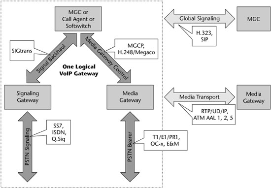
MGCP assumes a connection model where the basic constructs are endpoints and connections. Endpoints are sources and/or syncs of data and can be physical or virtual. Creation of physical endpoints requires hardware installation, while creation of virtual endpoints can be done by software. Connections can be either point to point or multipoint. A point-to-point connection is an association between two endpoints with the purpose of transmitting data between those endpoints. When that association is established for both endpoints, data transfer between them can take place. A multipoint connection is created by connecting the endpoint to a multipoint session. Connections can be established over several types of bearer networks. In the MGCP model, the gateways focus on the audio signal translation function, and the call agent handles the call-signaling and call-processing functions.
SIP
SIP, which is standardized under RFC 2543, is a peer-to-peer protocol in which end devices, known as user agents, initiate sessions. SIP is designed in conformance with the Internet model. It is an end-to-end signaling protocol, which means that all the logic is stored in end devices, except the routing of SIP messages. State is also stored in end devices only. There is no single point of failure with SIP, and networks designed this way scale well. The tradeoff for the distributiveness in scalability is the higher message overhead that results from the messages being sent end to end. The aim of SIP is to provide the same functionality as the traditional PSTN, but with an end-to-end design that makes SIP networks much more powerful and open to the implementation of new services.
SIP is an application-layer control protocol that can establish, modify, and terminate multimedia sessions. (Examples of a session include Internet telephone calls, distribution of multimedia, multimedia conferences, and distribution of computer games.) SIP can also invite participants to already existing sessions, such as a multicast conference. Media can be added to and removed from an existing session. SIP transparently supports name-mapping and redirection services, which make personal mobility possible. Users can maintain a single externally visible identifier, regardless of their network locations.
SIP support five facets of establishing and terminating multimedia communications: user location (the determination of the end system to be used for communication), user availability (the determination of the willingness of the called party to engage in communications), user capabilities (the determination of the media and media parameters to be used), session setup (the establishment of session parameters at both the called and calling parties), and session management (the transfer and termination of sessions, modification of session parameters, and invocation of services).
SIP can be used with other IETF protocols to build a complete multimedia architecture. For example, it can be used with RTP for transporting real-time data and providing QoS feedback, with Real-Time Streaming Protocol (RTSP) for controlling delivery of streaming media, with MGCP for controlling gateways to the PSTN, or with Session Description Protocol (SDP) for describing multimedia sessions. Although SIP should be used in conjunction with other protocols to provide complete services to users, the basic functionality and operation of SIP do not depend on any other protocols.
SIP, which works with both IPv4 and IPv6, operates as follows for Internet telephony sessions: Callers and callees are identified by SIP addresses. When making a SIP call, a caller locates the appropriate server and then sends a SIP request. The most common SIP operation is the invitation. Instead of directly reaching the intended callee, a SIP request may be redirected or may trigger a chain of new SIP requests by proxies. Users can register their locations with SIP servers; SIP addresses can be embedded in Web pages and, therefore, can be integrated as part of powerful applications such as click-to-talk.
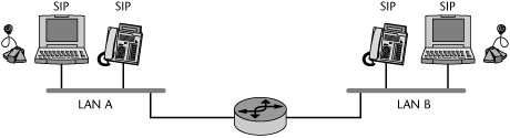
The purpose of SIP is just to make the communication possible (see Figure 9.6). The communication itself must be achieved by another means and possibly another protocol. As mentioned earlier, two protocols that are most often used along with SIP are RTP and SDP. RTP is used to carry the real-time multimedia data, including audio, video, and text. RTP makes it possible to encode and split the data into packets and transport the packets over the Internet. SDP is used to describe and encode the capabilities of session participants. This description is then used to negotiate the characteristics of the session so that all the devices can participate. For example, the description is used in negotiation of the codecs used to encode media so all the participants will be able to decode it and in negotiation of the transport protocol to be used.
SIP Network Elements
Basic SIP elements include user agents, proxies, registrars, and redirect servers (see Figure 9.7). User agents usually but not necessarily reside on a user’s computer in the form of an application, but user agents can also be cellular phones, PSTN gateways, PDAs, automated integrated voice response systems, and so on. User agents are often referred to as the user agent server (UAS) and user agent client (UAC). The UAS and UAC are logical entities only. Each user agent actually contains both. The UAC is the part of the user agent that sends requests and receives responses; the UAS is the part of the user agent that receives requests and sends responses.
Figure 9.7 SIP network elements
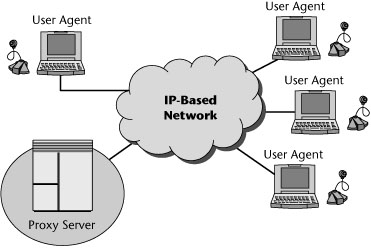
A proxy server is an optional SIP component. Proxy servers handle routing of SIP signaling, but they don’t initiate SIP messages. User agents can send messages to a proxy server. The most important task of a proxy server is to route session invitations closer to the callee. The session invitation usually traverses a set of proxies until it finds one that knows the actual location of the callee. Such a proxy then forwards the session invitation directly to the callee, and the callee then accepts or declines the session invitation.
A registrar server is another optional SIP component. It is a special SIP entity that handles registration from SIP user agents but does not route SIP messages. It receives registrations from users, extracts information about their current locations (such as IP address, port, and user name), and then stores the information in local databases. A registrar is very often a logical entity only and is usually collocated with proxy servers.
A redirect server is yet another optional SIP component. A redirect server receives requests and looks up the intended recipient of a request in the location database created by a registrar. It then creates a list of current locations of the user and sends this list to the request originator. The redirect server does not route SIP messages; rather, it returns a redirect to the user agent for direct routing.
SIP and Presence Systems
Presence is defined as the ability, willingness, desire, and capability of a user to communicate across media end devices and even time and space. Presence systems collect and distribute presence information to interested parties such as other users or applications. Policy—that is, who is allowed to see what and when—is central to presence. The value of presence is based on the richness of the data it has access to. Presence is the ability to see in real-time where someone is, how that person prefers to be reached, and even what the person is doing.
Today, only one in seven business calls is completed successfully. Instead, we get busy signals or are routed to voicemail. Users spend a lot of time trying many different numbers for the same person and calling many numbers in succession, trying to reach someone. Presence, therefore, has great value in improving the productivity of an organization because it can see ahead of time whether a call will succeed. It can tell the caller which is the best way to reach a user, and it can allow a caller to quickly see who among a set of candidates is available for a call.
Accuracy is paramount to presence. The greater the accuracy, the greater the value of presence. The worse the accuracy, the lower the value. Productivity enhancement depends on accurate presence data, and accuracy is achieved by combining multiple sources of presence data. There are many sources for presence data within an enterprise, such as detecting whether somebody is on a call or off a call, based on information from enterprise phones; determining whether a person is in a meeting or out of a meeting, based on information from the enterprise calendar systems; determining whether a person is in a conference or out of a conference, based on enterprise conferencing systems; or determining whether a person has logged in or logged out of the enterprise IM system.
Enterprise presence applications show presence on IP PBX phones and on PC-based IM applications. They can also support presence-based call routing as well as voicemail ringback. Two standards are involved in presence. The SIMPLE standard is a set of SIP extensions for IM and presence supported by Microsoft, IBM, Sun, and Novell. A competing standard, Extensible Messaging and Presence Protocol (XMPP), is an XML-based extensible open-source option that drives the Jabber IM client (www.jabber.com).
For all the good news about presence, there are also arguments against it. Most revolve around IM and the perception that it is intrusive and, at times, invasive. Most companies today use some form of IM, through mostly public services. The industry forecasts that we are only one to three years away from embedding presence in enterprise applications. Of course, standards, privacy, and security are major concerns.
SIP is creating new opportunities for platform providers that are introducing new soft phones. Proprietary soft phones incorporate SIP-based presence capabilities across both voice and IM, secure SIP-based IM behind the corporate firewall, IM archiving, click-to-talk voice functionality, speech-to-text functionality, and specialty modes for road warriors and telecommuters. There are also open-source SIP products. Not only do platform vendors have to worry about soft phones displacing their high-dollar hard phones, they have to worry about losing market share to some other open-source provider or to Microsoft.
Currently, SIP has no video specifications. When a vendor states that it uses SIP for video, it only means SIP is used for the signaling; it does not imply interoperability with other SIP video clients. In the near term, desktop video will be dominated by SIP-based endpoints, while the traditional group conferencing market will remain H.323 based; they will meet through SIP-to-H.323 gateways, as needed.
The SIP Forum (www.sipforum.org) and the IETF SIP protocol process are making it possible for many new SIP-based products to enter the market. SIP could disrupt the handset business, blurring the distinction between desk phones and mobiles because SIP can cross many boundaries, including desk phones, mobiles, PCs, PDAs, soft phones, intelligent appliances, and wearables.
SIP’s Strengths and Weaknesses
SIP’s strengths include tremendous industry support and widespread development. SIP soft phones, Ethernet phones, and application servers are available to integrate with IP clients and IM. SIP facilitates application development, and minimal call state duration is maintained in the network. SIP is central to all the latest solutions for telephony, ranging from hosted services to proprietary platforms, from handsets to soft phones to open-source software. The concepts behind SIP are disruptive and much more dramatic than VoIP on its own. The IETF still has a substantial amount of work to do to replicate in SIP the hundreds of TDM PBX calling features, but SIP is not just telephony: It involves many applications, such as presence, that enable capabilities that are not possible in the TDM world.
One shortcoming of SIP is a shortage of commercial and large-scale deployments at this time, resulting in a lack of real-world experience. Another problem is the lack of call state in the network, which affects billing and security issues. And of course, SIP is a moving target, with rapid development in progress. It is likely to be three to five years before presence and real-time communication standards become stabilized.
ENUM: Telephone Number Mapping
How do you find a telephone number on the Internet? How do you find islands of connectivity across domain boundaries? The answer is the Electronic Number Mapping Standard (ENUM). ENUM, defined in RFC 2916, is an IETF protocol that will assist in the convergence of the PSTN and the IP network. It maps a telephone number from the PSTN to Internet services: You put a telephone number in and get a URL out.
ENUM was developed as a solution to the question of how to find services on the Internet by using only a telephone number and how telephones, which have an input mechanism limited to 12 keys on a keypad, can be used to access Internet services. ENUM resolves a complete international telephone number to a series of URLs by using an architecture based on the Domain Name System (DNS). ENUM puts telephone numbers into the DNS, so it allows for a wide range of applications based solely on a phone number. Probably the most exciting application is an improvement in VoIP. Other applications include addressing for fax machines, e-mail, IM, and Web sites. The possibilities are enormous.
The ENUM protocol is the result of work of IETF’s working group for telephone number mapping (www.enum.org). The charter of this group was to define a DNS-based architecture and protocols for mapping a telephone number to a uniform resource identifier (URI) that can be used to contact a resource associated with that number. (The syntax of the URI is defined in RFC 2396.) The protocol itself is defined in the standards-track document E.164, which describes the international public telecommunication telephony numbering plan.
How ENUM Works
ENUM makes extensive use of the Naming Authority Pointer Resource Records (which are defined in RFC 2915) in order to identify available ways or services for contacting a specific node identified through the E.164 number. In a nutshell, ENUM involves the following steps:
1. ENUM turns a phone number into a fully qualified domain name (FQDN). It does this by first adding the city, or area, and country code. For example, 555-1234 dialed in Washington, DC, becomes +1-202-555-1234, where 202 is the area code, the 1 represents the North American country code, and the + indicates that the number is a fully qualified E.164 number. Then ENUM removes all the characters except for the digits and reverses the order (e.g., +1-202-555-1234 becomes 43215552021). Finally, it places dots between the digits and appends the domain E164.ARPA to the end of the string (e.g., 4.3.2.1.5.5.5.2.0.2.1.E164.ARPA).
2. ENUM issues a DNS query on the FQDN created in step 1.
3. DNS returns a list of URIs that contain information about what resources, services, and applications are associated with that specific phone number.
An important feature of the ENUM protocol is that more than one type of contact information can be stored in the DNS record that belongs to a specific ENUM number. An ENUM record associated with The LIDO Organization might contain instructions for a VoIP call (e.g., h323:[email protected] or sip:[email protected]), a fax call (e.g., fax:[email protected]), and e-mail communications (e.g., mailto:[email protected]). Additional services can be developed in the future and included in the ENUM name records. The phone number in ENUM can therefore be the single contact number for multiple types of communication, such as voice, fax, e-mail, mobile, text messaging, location-based services, and Web pages.
ENUM does not replace the numeric IPv4 or IPv6 addresses that will be used to interact within IP directly. ENUM performs no conversion of signaling messages and media streams. Instead, ENUM is a framework for mapping and processing addresses of different network types. ENUM provides another way to determine the desired destination to be used to initiate communication over a next-generation network. Although ENUM will help facilitate VoIP calls, it is important to understand that VoIP phone calls do not require ENUM, and ENUM implementation is not mandatory, at least not at this point. VoIP calls can be made wholly without ENUM by using their defined Internet addressing scheme (e.g., sip:user@host.com).
The Future of ENUM
The Internet Architecture Board (IAB; www.iab.org) and ITU Study Group 2 are discussing a collaboration on the operational administration and delegation issues related to deployment of ENUM-based services. As you can imagine, this requires extensive consultation with administrators of resources derived from the international E.164 numbering plan, including national and international numbering plan administrators.
Under current practice, service providers generally develop their own address-mapping solutions and negotiate their own traffic exchange arrangements among themselves. Experts predict a gradual shift toward public ENUM as the number of IP voice endpoints grows. The following ENUM structures are possible:
- Private ENUM—Service and equipment providers are finding ways to make money on private ENUM, or ENUM-like, proprietary mapping and signaling. ENUM creates and enables the opportunity for a third party to enter and build the technology and then make money by charging fees to all the different providers who have numbers stored in the system. In this scenario, the third party would make fractions of a penny per number, per month. A grander vision would include transport service between VoIP providers, combining call routing and transmission. The service providers would have to have a sufficient number of customers and amount of traffic to warrant such services.
- User ENUM—User ENUM gives end users on the Internet and end users on the PSTN a possibility to find services of other end users on the public Internet. In this case, ENUM service providers provide a form of electronic business card or basic buddy list. The phone number becomes a universal key that is globally accessible by all potential correspondents of the user. With user ENUM, the data is public. Anyone who knows the universal key—that is, the phone number—can have access to the information, which may have privacy implications. Even if the user subscribes to several applications and services, the user would remain the only party who has complete control over the set of identifiers. User ENUM is a capability provided for end users and is optional both for the calling user and for the called user.
- Infrastructure ENUM—Network operators using IP-based technology within their networks cannot rely on an optional technology used by end users. They need an independent routing mechanism to find the ingress points to their networks. Using DNS and ENUM technology for this purpose, as described in RFC 3761, is called infrastructure ENUM, or carrier, or operator, ENUM. The basic premise of infrastructure ENUM is to provide information only to IP service providers and, in some cases, only to selected peers. The end user typically cannot use this information or has no access to it. This type of system must be implemented as an independent system.
If every IP communications service provider is only providing data for numbers hosted by the operator itself, a later merging of trees should not be a problem. If, on the other hand, providers are entering data for numbers they are not hosting themselves (e.g., data for numbers where they provide transit services), a later merging of trees will cause problems. Therefore, it is not recommended to use infrastructure ENUM for providing transit information.
Another application for infrastructure ENUM technology is to provide access to national number portability information, which is currently stored in databases. However, this information will have only national significance (e.g., national routing numbers). As a result, this data cannot be used in supranational infrastructure ENUM implementations.
The reality is that ENUM is not currently required in networks, based on the type of applications that carriers and service providers are supporting. In terms of U.S. domestic policy, the U.S. government endorses moving forward with ENUM based on the concept of an industry management limited liability corporation similar to that used with number portability. It involves an arm’s-length contractual relationship with an administrative entity. This is similar to existing relationships with ICANN (www.icann.org) for IP address space, top-level domain names, and root server management; with NeuStar (www.neustar.com) for numbering plan and portability management; and with VeriSign (www.verisign.com) for .com and .net registries.
The U.S. ENUM Forum (www.enumf.org) is developing policies and taking steps to implement ENUM in the United States. Some early participants include AT&T, Sprint, SBC, Verizon, Neustar, Cox Cable & Wireless, Cisco, and Telcordia. However, it is anticipated that it will be a while before the United States sees public ENUM. Several national forums are under way in the United Kingdom, Austria, Sweden, Japan, the Netherlands, Germany, Brazil, Austria, Poland, and elsewhere. A number of resources are available on the Web, including the approved ENUM delegation list (www.ripe.net/enum/request-archives) and the ITU ENUM Web page (www.itu.int/osg/spu/enum/index.html).
IPTV
IPTV is generally described as a system that delivers digital television service to a subscriber using IP over a broadband connection, often provided in conjunction with video-on-demand (VOD), Internet services, and VoIP, as part of triple-play services (a combination of voice, data, and video services over the same infrastructure). In its simplest definition, IPTV is the delivery of television content through technologies used for the World Wide Web rather than traditional formats.
Some say that incumbent telcos have developed their current interest in offering video or TV services as a result of fear—fear that cable operators are beginning to encroach on their territory with residential voice services, fear that competition is eroding the number of access lines being deployed, and fear that traditional landline revenues will continue to fall even further. IPTV therefore holds great promise for telcos. But more importantly, with IPTV, telcos and cable providers alike can offer triple-play services. It is also important to note that IPTV is not just a replication of the passive cable TV viewing environment of old; instead, it offers services including interactive gaming, access to massive libraries of video content on demand, and e-commerce activities, with a view to future features such as energy management and security services.
IPTV was not possible in the dialup era, when the download speeds were far too slow to allow any type of video content to be received, let alone enjoyed. With the penetration of broadband growing daily, IPTV is becoming available to more households. The market research firm Research and Markets expects the number of global IPTV subscribers to grow from 4.3 million in 2005 to 36.8 million in 2009, at a compound annual growth rate of 72%. Europe is leading the market for subscriber numbers, while Asia and North America have fallen off slightly due to a slower-than-expected rate of fiber deployment (“Global Users Tune In to IPTV,” www.vnunet.com/vnunet/news/2154560/iptv-set-rocket). Needless to say, many if not most of the world’s leading telecom providers are investigating IPTV, in the search for a new revenue-generating opportunity and as a defensive measure against the ever-increasing encroachment of cable TV operators. Because IPTV relies on IP, it promises lower costs for providers and lower prices for consumers—what appears to be a win–win situation.
IPTV supports both live TV (multicasting) and VOD (stored video). IPTV is viewed on a TV and requires a set-top box. The video content is usually in MPEG-2 TS (Transport Stream) format, delivered via IP Multicast. IPTV was specifically designed to deliver high-quality content to a traditional TV through the Internet. From the consumer’s point of view, the experience with IPTV is very similar to the experience with cable or satellite.
One of the main advantages of IPTV is its two-way capability, which traditional TV distribution technologies do not have. Another benefit is its point-to-point distribution, which allows each viewer to view individual broadcasts. This functionality enables stream control (pausing, forwarding, rewinding, and so on) and a free selection of programming similar to what the Web offers. As mentioned earlier, IPTV enables providers to offer more services over the same pipe (e.g., triple-play services).
Of course there are alternatives to IPTV, encompassing traditional TV distribution technologies such as terrestrial, satellite, and cable TV. Because cable can be upgraded to two-way capability, it can also carry IPTV.
IPTV Versus Streaming Media
Streaming media is an almost identical server-side technology to IPTV, but it terminates on a PC rather than on a TV. Streaming media is still difficult to sell to broadcasters and is not a hot topic of discussion because it does not leverage the TV sets already out there. The general perspective is that if you’re a television professional, computers are not really part of your world. In fact, from a broadcaster’s point of view, it would be better if computers simply disappeared because they take away traditional TV viewers.
With IPTV, the network operator controls the entire path—from the time the content is assembled to the delivery of that content to the consumer’s TV set. The operator can set the QoS and control the security. In the streaming media model, the signal is likely to traverse different providers’ networks, so the network operator doesn’t have the same control over bandwidth and QoS. The deployment of IPTV is greatly affected by the need for end-to-end control. IPTV does not involve a signal being sent from one end of the world to the other; it is regional or local, and IPTV is therefore being implemented by companies that own entire networks.
Because IPTV is a closed, managed network, it can deliver full-screen, high-quality video content, unlike streaming media, which is most often still relegated to small-screen and relatively low-quality video. For streaming media, network capacity is a critical issue that needs to be resolved if it is to have any hope of not only keeping up with but converging with IPTV. High-definition TV (HDTV) is setting another benchmark that streaming media might struggle with.
For telcos in particular, IPTV is laying the foundation for the future, allowing the provider to serve the customer with a bundle of offerings, as well as establishing a position in the nascent market for online video distribution. Aside from TV, there are a multitude of opportunities for future multimedia applications that involve the integration of voice, data, and video. Examples of these types of services include displaying caller ID on a TV set to being able to program a personal video recorder (PVR) remotely from a handheld device.
The IPTV Architecture
Using IPTV requires either a PC or a set-top box connected to a TV (see Figure 9.8). The primary underlying protocols used for IPTV are Internet Group Management Protocol (IGMP) version 2 for channel-change signaling for live TV and RTSP for stored video (i.e., VOD).
Figure 9.8 The IPTV architecture
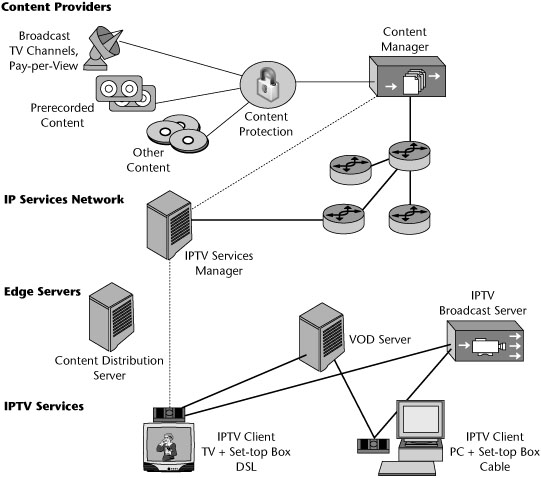
Protocols that use peer-to-peer technology to distribute live TV are just starting to emerge. Their primary advantage over traditional distribution models is that they provide a way to share data delivery workloads across connected client systems as well as the distributor’s own server infrastructure, which drastically decreases the operational costs for a stream provider. Video compression formats used for IPTV include MPEG-2, MPEG-4, H.264, WMV (Windows Media Video 9 and VC-1), XviD, DivX, and Ogg Theora. (Compression techniques are discussed in Chapter 10.)
VPNs
VPNs are a crucial requirement for businesses because they distribute mission-critical and sensitive traffic to remote locations. More and more often, customers are looking at mechanisms for securing traffic and for extending the reach of the enterprise to geographically dispersed locations. VPN technology is also being extended to the home office, providing telecommuters with networking security and performance comparable with that available at the office.
A big driver of interest in VPNs has been that customers need to communicate with people outside their enterprise, not just those inside the enterprise. As mentioned in Chapter 5, “Data Communications Basics,” in the 1980s, about 80% of the information that was used within a given address of a business came from within that address. Only 20% was exchanged outside the walls of that location. Today, the relationship has reversed: As much as 80% of information exchanged is with points outside a given business address.
Another reason for interest in VPNs has been that customers want to quickly and securely change their access points as changes occur in their businesses. Many strategic alliances and partnerships require companies to exchange messages quickly. Some of these are temporary assignments—for example, a contractor building a fiber-optic loop or an applications developer building a new billing system—that might last a few months, during which time the individuals involved need to be incorporated into the network. Leased lines are infamous for requiring long waits for provisioning—often 6 to 18 months. VPNs allow rapid provisioning of capacity where and when needed.
Traffic has steadily migrated away from traditional networks based on leased lines (see Figure 9.9) to public networks. As a result, we’re seeing a steady growth in the pseudoprivate realm of the VPN (see Figure 9.10). A VPN is a logical network that isolates customer traffic on shared service provider facilities. In other words, the enterprise’s traffic is aggregated with the traffic of other companies. VPNs have been around for quite some time—since X.25 closed user groups on the packet-switched network and the AT&T Software-Defined Network (SDN) on the circuit-switched networks. A VPN looks like a private network, but it runs across either the public circuit-switched network or public packet-switched data networks. Thus, a VPN is not just a solution within the IP realm; a VPN is a concept, not a specific set of technologies, and it can be deployed over a wide range of network technologies, including circuit-switched networks, X.25, IP, Frame Relay, ATM, and MPLS.
Figure 9.9 An enterprise network based on leased lines
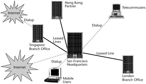
Figure 9.10 An enterprise network using a VPN
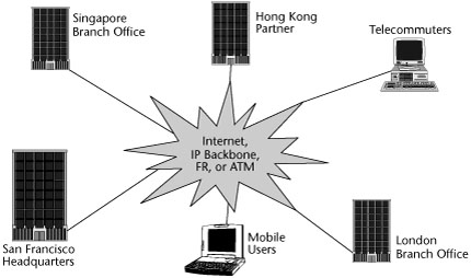
With the advances in VoIP and Video over IP, consumers have realized that they can converge real-time applications such as voice, video, and data into one access circuit. Carriers have realized that with the evolution of converged technologies, they no longer need to deploy, maintain, and support both TDM and IP backbones. However, carriers’ IP backbones provide neither segmentation of customer traffic nor the security normally associated with that segmentation. Under the initiative of service providers, the standards organizations have recognized the value of starting work on the standardization of VPN technology, through ITU-T Study Group 13 and the IETF Provider Provisioned VPNs (PPVPNs) group. These standardization efforts have focused on the provider-provisioned class of VPNs. Today’s provider-provisioned and provider-managed VPNs are intended to emulate whatever LAN or WAN connectivity a customer desires.
The following sections discuss key VPN concepts, types of VPNs, and VPN security.
Key VPN Concepts
A VPN uses a shared carrier infrastructure. It can provide additional bandwidth on demand, which is an incredible feat, compared to the weeks it normally takes to add bandwidth to dedicated networks. Carriers build VPNs with advanced survivability and restoration capabilities, as well as network management tools and support, so that QoS can be considered and service-level agreements (SLAs) can be administered and met.
There are two major models of VPNs:
- Customer edge model—This customer-based model requires the CPE to be fully capable of configuring and provisioning the VPN and thereby results in higher operating expenses for the enterprise user. The routing intelligence resides at the end-user’s site. Service providers install gateways, routers, and other VPN equipment on the customer’s premises. Because this requires the service provider to manage onsite equipment, the cost associated with the onsite visits from field engineers can be high. This approach is generally preferred where the customer wants to have control over all aspects of security.
- Provider edge model—In this model, the VPN intelligence resides at the provider’s edge, where it can be extended out to many end-user locations. The carrier houses all the necessary equipment at a point of presence (POP) near the customer’s location. This offers the advantages of scalability, support of an increasingly diverse range of IP-based services, and efficient prioritization of traffic. It provides the foundation needed to integrate fixed and mobile VPN communications into one seamless framework. This approach is generally preferred by customers who want to take advantage of the carrier’s VPN economies of scale.
VPN Frameworks
Contemporary VPNs can be described as belonging to one of three categories: Internet-based VPNs, provisioned VPNs, and IP-based VPNs. The following sections define the nature of these types of VPNs.
Internet-Based VPNs
In an Internet-based VPN (see Figure 9.11), smaller ISPs provide local access services in defined geographical regions, requiring an enterprise to receive end-to-end services from multiple suppliers. An Internet-based VPN uses encryption to create a form of closed user group, thereby isolating the enterprise traffic and providing acceptable security for the enterprise across the public shared packet network. However, because it involves multiple ISPs in the delivery of the VPN, the performance is unpredictable. The biggest problem of having multiple suppliers is the inability to define and meet consistent end-to-end bandwidth or performance objectives.
Figure 9.11 An Internet-based VPN

Figure 9.12 shows what is involved in providing an Internet-based VPN. The customer has on the premises a wide variety of servers that dish up the corporate content, the finance systems, the customer service systems, and so on. A VPN is responsible for the encapsulation of the information and hence the security aspects. Remote Authentication Dial-in User Services (RADIUS), an authentication and access control server, is used to authenticate a user who wishes to access corporate resources. The RADIUS server connects to a directory server, which contains the user accounts of those allowed to access the network. Traffic from the VPN server usually passes through a firewall, which determines whether traffic is allowed into or out of the network. The router selects the optimum path for the messages to take, and the circuit physically terminates on a channel service unit/data service unit (CSU/DSU). A private line interfaces with the Internet provider’s POP. From that point, the VPN either uses the public Internet that comprises multiple ISPs or relies on IP backbones provided by an individual provider or at least a small group of providers. Users who are working on mobile devices have laptops equipped with the client and VPN services necessary for encapsulation and for administration of security.
Figure 9.12 The parts of an Internet-based VPN
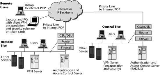
Provisioned VPNs
VPNs rely on the capability to administer preferential treatment to applications, users, and so on. The public Internet does not support preferential treatment because it is subject to delay, jitter, and loss; it is therefore unsuitable for next-generation services that require high performance. In most cases, to accommodate business customers that are interested in such advanced services and that demand SLAs, the underlying transport is Frame Relay or ATM. Frame Relay and ATM VPNs offer greater levels of QoS and can fulfill the SLAs that customers and vendors agree to. However, they require that the customer acquire an integrated access device (IAD) to have on the premises, which can increase the deployment cost significantly. IADs enable the enterprise to aggregate voice, data, and video traffic at the customer edge.
A provisioned VPN (see Figure 9.13) is a packet-switched VPN that runs across the service provider’s backbone, generally using Frame Relay or ATM. This type of VPN is built on OSI model Layer 2 virtual circuits, such as those used by Frame Relay, ATM, or MPLS, and it is provisioned based on customer orders. Virtual circuits based on predetermined locations create closed user groups and work well to carve out a VPN in a public shared network by limiting access and usage to the provisioned VPN community. However, encryption is still required to securely protect the information from theft or modification by intruders.
Figure 9.13 A provisioned VPN
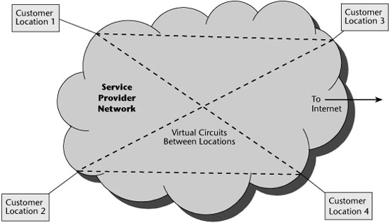
A provisioned VPN is differentiated from an IP-based VPN by its ability to support multiple protocols and by the fact that it offers improved performance and management. These VPNs are characterized as having excellent performance and security, but the negative is that a single vendor may not offer the necessary reach and breadth in terms of service offerings.
Figure 9.14 shows what the CPE looks like for a VPN based on Frame Relay or ATM. The customer has an IAD that allows voice and data to be converged at the customer premises. The IAD feeds into the data communications equipment, over which a circuit goes to the service provider’s POP. At the service provider’s POP is a multiservice access device that enables multiple protocols and interfaces to be supported and that provides access to the service provider’s core network, which is based on the use of Frame Relay or ATM. To differentiate Frame Relay–and ATM-based VPNs from IP-based VPNs, service providers stress that multiple protocols are supported and that they rely on the use of virtual circuits or MPLS labels to facilitate the proper path, thereby ensuring better performance and providing traffic management capabilities.
Figure 9.14 A Frame Relay- or an ATM-based provisioned VPN
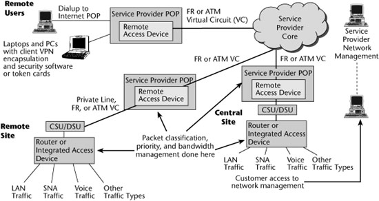
To further differentiate Frame Relay–or ATM-based VPNs from regular Frame Relay or ATM services, additional functions—such as packet classification and traffic isolation, the capability to handle multiple separate packet-forwarding tables and instances of routing protocols for each customer—reside at the edge.
IP VPNs
Whereas Internet-based VPNs tend to involve numerous ISPs, IP-based VPNs tend to involve IP backbones that are under the control of a given service provider or a customer-owned enterprise network. An IP VPN is basically a private, or restricted, communications network constructed over shared IP-based networks, usually serviced on the providers’ backbones, but with connections to the public Internet. IP-based VPNs have traditionally been referred to as networks of secure links over a public IP infrastructure. However, today an IP VPN is likely to be an MPLS-based infrastructure. (BGP MPLS VPNs are discussed later in this chapter.) However, as far as the user is concerned, the experience is the same, regardless of the technique. IP VPN services provide secure access for connecting intranets to other intranets, support mobile and teleworker access to their enterprise intranets, and provide for the connection of extranets to private enterprise, education, and government networks.
As discussed later in this chapter, there are two broad categories of IP VPNs:
- Network-based VPNs—With a network-based VPN, all the routing intelligence and VPN topology for the VPN are provided on the carrier’s provider edge. Network-based IP VPNs make life much easier for users: Because all of the VPN topology is stored on the carrier’s provider edge, the provider has the responsibility of managing all the complexity of the VPN topology. All the customer needs is a single connection from the CPE to the provider edge.
- CPE-based VPNs—In the case of CPE-based VPNs, which are most often based on IPsec, the network topology is defined at the customer’s edge router. Obviously, with large or highly meshed networks, the management of so many tunnels and VPN rules can be overwhelming and can severely affect the capabilities of customers’ edge routers.
IP VPNs are discussed in detail later in this chapter.
The goal of a VPN is to provide connectivity over a shared infrastructure that is as secure and cost-effective as a dedicated private network such as a Frame Relay or ATM network. In addition, a VPN solution must be scalable, highly available, and easy to manage. And of course, QoS is a required feature. A VPN works by using the shared public infrastructure while maintaining privacy through security procedures and tunneling protocols, such as Point-to-Point Tunneling Protocol (PPTP), Layer 2 Tunneling Protocol (L2TP), Generic Routing Encapsulation (GRE), and IP Security (IPsec).
In effect, the protocols, by encrypting data at the sending end and decrypting it at the receiving end, send the data through a tunnel that cannot be entered by data that is not properly encrypted. An additional level of security involves encrypting not only the data but also the originating and receiving network addresses. Tunneling is the transmission of data intended for use only within a private, usually enterprise, network through a public network in such a way that the routing nodes in the public network are unaware that the transmission is part of a private network.
As shown in Figure 9.15, tunneling is generally done by encapsulating the private network data and protocol information within the public network transmission units so that the private network protocol information appears to the public network as data. Tunneling allows the use of the Internet, which is a public network, to convey data on behalf of a private network. VPN tunneling is not intended as a substitute for encryption and decryption. In cases where a high level of security is necessary, the strongest possible encryption should be used within the VPN, and tunneling should serve only as a convenience. Some tunneling protocols include encryption: PPTP includes MPPE (Microsoft Point-to-Point Encryption, based on RC-4), and IPsec specifies a tunnel mode typically used in gateway-to-gateway (but not client-to-gateway) communications. (VPN security is covered in detail later in this chapter.)
Figure 9.15 VPN tunneling
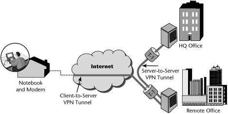
Customers and providers can employ various flavors of point-to-point tunnels to serve as logical links in an IP VPN. An IP VPN tunnel connects two sites or a user to a site by imposing a separate tunnel header on the VPN data packet at the source site and disposing of the tunnel header at the destination site. This lets VPN data packets travel opaquely through the public Internet, independent of their payload or header content.
Applications of VPNs
A VPN is an architecture, a series of products and software functions tied together and tightly calibrated. Managing a VPN entails dealing primarily with two issues: monitoring security policies and parameters, and ensuring that applications function within the latency requirements. It is important to be able to effectively and easily manage the VPN environment. You need to consider how easy it is to track a VPN’s tunnel traffic, support policy management, track QoS, track security infractions, and support public key certificate authorities (CAs). Managed VPN services—the one-stop-shopping approach to VPNs—are designed to lock in users and to reduce costly customer churn, but with this approach, interoperability is very restricted. Managed VPNs provide capabilities such as IP connection and transport services, routers, firewalls, and a VPN box at the customer site. Benefits of this approach include the fact that it involves a single service vendor, SLAs, guaranteed latency and bandwidth, and the security of traffic being confined to one network.
VPN applications provide maximum opportunities to save money and to make money—by substituting leased lines with Internet connectivity, by reducing costs of dialup remote access, and by stimulating new applications using extranets. These savings can be substantial.
The three major applications of VPNs—intranets (i.e., site-to-site VPNs), remote access, and extranets—are examined in the following sections.
Intranet VPNs
Intranet VPNs are site-to-site connections (see Figure 9.16). The key objective of an intranet VPN is to replace or reduce the use of leased-line networks, traditional routers, and Frame Relay services. The cost savings in moving from private networks to Internet-based VPNs can be very high, in the neighborhood of 50% to 80% per year. Remember that Internet-based VPNs allow less control over the quality and performance of applications than do provisioned VPNs; this is a bit of a deterrent, and many clients still want to consider Frame Relay–or ATM-based VPNs, which provide better QoS. The savings might drop a bit, but the cost of a provisioned VPN would still be substantially less than the cost of using leased lines.
Figure 9.16 An intranet VPN
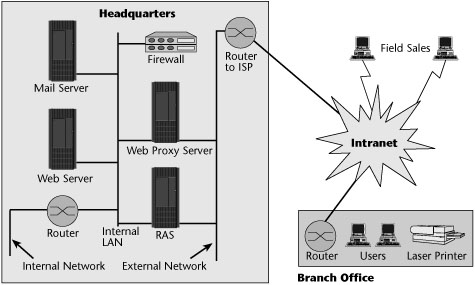
There are two key barriers to building more intranets based on VPNs: First, there is a variance between vendors’ products that leads to interoperability problems, and second, today’s Internet is unable to provide end-to-end QoS.
Remote Access VPNs
The most interesting and immediate VPN solution for most customers is the replacement of remote access servers. VPN remote access implementations can save customers from 30% to 70% over traditional dialup remote access server deployment. Remote access servers provide access to remote users, generally via analog plain old telephone service (POTS) lines, or, perhaps, ISDN connections, including dialup protocols and access control for authentication (administered by the servers). However, a remote access server requires that you maintain racks of modems, the appropriate terminal adapters for ISDN services, or DSL-type modems for DSL services. You also need remote access routers, which connect remote sites via a private line or public carriers and provide protocol conversion between the LANs and WANs. To have an internal implementation of remote access, you have to acquire all these devices, as well as the talent to maintain them.
If an enterprise needs remote access connections outside local calling areas, and/or if it needs encrypted communications, it is generally fairly easy to justify a VPN service rather than an enterprise-based remote access server. The initial cost of hardware for a VPN approach is about 33% less than the cost of hardware for a traditional dialup remote access server deployment. The customer also saves on charges for local access circuits, and costly toll and international charges are eliminated.
By virtue of supporting a greater range of customers, a service provider that offers VPN-based remote access is more likely to support a wider variety of broadband access options, including xDSL, cable modems, and broadband wireless. VPN-based remote access also reduces the management and maintenance required with modem banks and remote client dial-in problems. For these reasons, remote access represents the primary application for which customers turn to VPNs. Figure 9.17 shows an example of a remote access VPN.
Figure 9.17 A remote access VPN
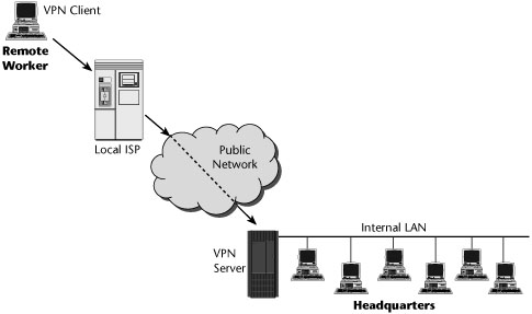
Extranet VPNs
Extranet VPNs allow an external organization to have defined access to an enterprise’s internal networks and resources (see Figure 9.18). There are three major categories of extranets: supplier extranets, which focus on speeding communications along the supply chain; distributor extranets, which focus on the demand side and provide great access to information; and peer extranets, which create increased intraindustry competition.
Figure 9.18 An extranet VPN
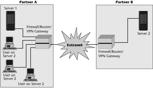
The key applications for extranets include distribution of marketing and product information, online ordering, billing and account history, training policies and standards, inventory management, collaborative research and development, and e-mail, chat, news, and content.
Benefits and Evolution of VPNs
The main benefit of VPNs as compared to leased-line or Frame Relay networks is cost savings. VPNs also optimize environments that use IP; they have less overhead than Frame Relay, and tunneling protocols may eliminate the need for proprietary encapsulation of protocols. Provisioned VPNs also have the additional benefits of Frame Relay and ATM in the administration of virtual circuits and QoS. VPNs also provide the capability to support dialup access, and greater redundancy is achieved in the network by virtue of meshed nets. In addition, VPNs do not necessarily demand an end-to-end digital fiber infrastructure.
VPNs are undergoing an evolution, and various parameters still need to be addressed. Among those are the QoS guarantees. Effective traffic prioritization is at the heart of QoS, and currently available mechanisms include Differentiated Services (DiffServ), Class-Based Queuing (CBQ), Common Open Policy Service (COPS), and MPLS. (These mechanisms are covered in Chapter 10.) Other areas of evolution in VPNs are tiering of VPN services (i.e., bandwidth tiering and different policy management), the capability to support autoprovisioning, and the emphasis on security.
QoS and security are the two most important considerations in administering VPNs, so uptimes, delays, and SLAs need to be structured. For example, QoS guarantees could promise 100% premises-to-premises network availability, with a maximum latency of 80 milliseconds. Some vendors offer separate SLAs for dedicated and remote access. For dedicated access, the SLA may offer an availability guarantee of 99.9% and a maximum latency guarantee of 125 milliseconds. On remote access SLAs, a busy-free dial availability guarantee of 97% may be stipulated, and the latency guarantee would depend on the initial modem connection speed.
Today, three basic types of carrier-managed IP VPN services are offered:
- CPE-based IPsec VPNs—These VPNs are generally used to support site-to-site enterprise VPNs and have, in many ways, become the gold standard for VPN security, especially when traffic is running over the public Internet.
- Network-based IPsec VPNs—These VPNs may run over the Internet or the service provider’s private IP facilities. Customers use leased-line connections from the premises router to the service provider’s POP.
- Network-based MPLS VPNs—These VPNs are receiving the most attention today. Service providers’ VPN solutions can be deployed using partial mesh, full mesh, and hub-and-spoke designs. They can provide point-to-point and multipoint connectivity. They support a multitude of services and are available from multiple providers around the world.
VPN Standards
The initial VPN service standardization efforts focused on service provider Layer 3 solutions, where multiple competing implementations had already been developed. The main driving forces of the standards initiatives included multivendor interoperability and applicability scenarios of each of those Layer 3 solutions. Later, the interest in Layer 2 provider edge–based solutions was driven by the growing attractiveness of the metro-Ethernet market and the capability to offer relatively simple migration paths from traditional Layer 2 ATM and Frame Relay services to network-based VPNs over an IP infrastructure.
The ITU-T has been mainly developing requirements, architecture elements, and Layer 1 architectures and is currently working on generalized VPN architectures and QoS aspects. The IETF has focused on Layer 3 and Layer 2 solutions and related applicability scenarios. Finally, the Ethernet-based Layer 2 VPN domain covers areas of interest for various standards communities. The Metro Ethernet Forum (www.metroethernetforum.org) is one of the major groups working on solutions to offer Ethernet Layer 2 VPNs using Ethernet metro or core networks.
Types of IP VPNs
IP-based VPNs were initially deployed to address two specific market segments:
- Virtual private dial networks (VPDNs)—VPDNs were developed for telecommuters and road warriors who needed secure and convenient access to their enterprise servers (see Figure 9.19). This approach has included the use of PPTP, L2TP, or IPsec. With a VPDN, the end user establishes a user-to-corporate-gateway point-to-point session that travels over a combination of two links: a dialup data link to the Internet service provider edge and a VPN tunnel (sometimes called a voluntary tunnel) from the user to the enterprise gateway (less common is a compulsory tunnel, established from the ISP edge to the enterprise gateway). L2TP supports the tunneling of PPP sessions containing user data through the Internet, but by itself isn’t secure; L2TP connections are clear text. L2TP is usually combined with IPsec to achieve the required privacy. Residential dialup access to the Internet uses similar technology. Broadband provides additional options, including the use of cable links, DSL links, or 802.11 in the wireless realm.
- Site-to-site VPNs—Site-to-site VPNs were developed for enterprises desiring to communicate over the public Internet but requiring data integrity authentication and privacy. The main approach has included the use of IPsec or GRE. However, many more options are now available, especially in the provider edge–based arena. As shown in Figure 9.20, provider edge–based VPNs are available as Layer 3 VPNs and Layer 2 VPNs. Layer 3 VPNs offer two choices: RFC 2547 and virtual routers. Layer 2 VPNs also offer two choices: virtual private wire service (VPWS) and Virtual Private LAN Services (VPLS).
Figure 9.19 VPDN solutions
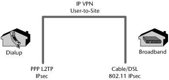
Figure 9.20 Site-to-site VPN solutions
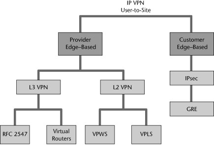
The following sections describe the various types of site-to-site VPNs.
IPsec VPNs
IPsec has been around for quite some time and is offered by most service providers as a mechanism for tunneling traffic across the Internet to areas where the provider does not have POPs. In order to address the heightened security requirements, the customer or the provider managing the CPE routers can build IPsec security associations (not called tunnels unless using a specific type of security association, known as tunnel mode, described shortly) across the Internet to interconnect CPE. In order to authenticate and encrypt the user data, packets are forwarded across the shared Internet. IPsec uses a variety of protocol exchanges and encapsulations at the endpoints.
IPsec is an IETF protocol suite that addresses basic data integrity and security. It covers encryption, authentication, and key exchange. It supports key sizes of varying lengths, depending on the capabilities of each end of the connection. IPsec emphasizes security by authenticating both ends of the connection, negotiating the encryption protocol and key for the encrypted session, and encrypting and decrypting the session establishment data. IPsec provides secure transmission of packets at the IP layer, including authentication and encryption of the packets. This is accomplished by using the authentication header and encapsulating security payload features of IPsec.
IPsec uses transport and tunnel modes. In transport mode, only the IP payload is encrypted. There is no change to the original IP header. This is generally used between hosts or routers and also in client/server VPNs. In tunnel mode, the entire IP datagram is encrypted; the original packet is encapsulated in IPsec and given a new IP header. This mode is generally used between gateways.
Internet Key Exchange (IKE), which is defined in RFC 2409, is the key exchange protocol that IP Security (IPsec) uses in computers that need to negotiate security associations—that is, connections between systems, established for the purpose of securing the packets transmitted across the connections—with one another. Although IPsec is optional in IPv4, in IPv6, providing security through IPsec and, in turn, IKE is mandatory.
With IKE, public key techniques are used to mutually authenticate the communicating parties. IKE supports both digital certificates and preshared keys for authentication. IKE uses a Diffie-Hellman key exchange to set up a shared session secret from which the bulk cryptographic keys are derived. If you use preshared keys, then every node must be linked to every other node by a unique key, and the number of keys needed can grow out of control (e.g., two devices need 1 key, and eight devices need 28 keys). That’s why most production implementations of IPsec use digital certificates issued most often by internal certificate authorities. IKE version 2 (IKEv2), defined in RFC 4306, expands upon IKEv1. (Public keys, digital certificates, and CAs are discussed later in this chapter.)
Initially, IPsec became the predominant mechanism for providing the underlying VPN architectures. This technology works at OSI Layer 3 to create a connection into the network so that as a device logs on, it can act as if it is physically attached to the LAN. By encrypting the traffic, the customer can build VPN networks over the Internet. A customer’s traffic is encrypted but not necessarily segmented. IPsec provides encryption and authentication, but there is a tradeoff in performance, although most modern hardware can handle the cryptographic requirements well enough. In general, IPsec is inefficient because it requires significant overhead to encrypt the traffic. This may be acceptable on low-speed links, but throughput is significantly affected on high-speed links. Most router vendors provide IPsec capabilities embedded in the operating systems, but there is a significant performance degradation in the routers.
Line-speed IPsec processing is still not where most customers would like it to be. You need to take this into consideration when choosing a routing platform that will be initiating IPsec security associations. In addition to the performance impact, there is the additional management overhead of configuring, maintaining, and managing IPsec across the IP cloud. IPsec, key distribution, key management, and peering configuration can become complex in a large IPsec deployment.
RFC 2784 and RFC 1702 specify the GRE protocol for using IP as both the delivery and payload protocol. In the most general case, a system has a packet that needs to be encapsulated and delivered to some destination, referred to as the payload packet. The payload is first encapsulated in a GRE packet. The resulting GRE packet can then be encapsulated in some other protocol and forwarded. This outer protocol is referred to as the delivery protocol.
GRE is a simple stateless protocol that allows for the tunneling of IP in IP. GRE tunnels can be used to form VPNs, connecting remote sites by using private IP addresses via a public network. These tunnels are configured between provider edge routers and are transparent to the rest of the network. GRE VPNs currently have simple support for QoS. By default, the DSCP value in each payload header is copied into the tunnel header. This means that any QoS policy for IP packets can be applied to GRE-encapsulated packets as well. An added benefit is that GRE VPNs provide adjacencies directly between customer routers.
GRE VPNs provide a complete separation between customer and provider routing (see Figure 9.21). Customers can run their own routing protocols across the VPN and have no interaction with provider protocols. An internal gateway protocol dedicated to customers, such as OSPF or IS-IS, can be run across a provider network with strict separation from the provider’s internal or external routing protocols. If customers are transitioning from a private enterprise network, they may be able to use this approach to preserve much of their internal gateway protocol configuration.
Figure 9.21 IP GRE VPNs

Key concepts in GRE VPNs include multiple contexts and multiple interfaces:
- Contexts—A GRE router’s VPN solutions all rely on contexts, which are virtual routers running within single physical devices. A context has its own IP address space, routing table, user authentication, logging and debugging functions, and other attributes. Customers get a dedicated context for each VPN.
- Interfaces—Virtual or logical interfaces enable physical ports or circuits to be individually mapped to different contexts through simple configuration commands. An interface is a logical entity that holds an IP address and is configured as part of a context. Interfaces are independent of physical ports and circuits. An interface can pass traffic only when it is bound to, or associated with, a physical port or circuit. This binding process can be changed at any time so that a customer port can easily be mapped to one context and then remapped to another with only one line of configuration code.
GRE routers can carry multicast traffic in GRE tunnels. Carriers can, therefore, distribute multicast traffic, such as video, in GRE VPNs or use GRE tunnels to carry multicast traffic through a unicast network. The latter application is ideal when a carrier wants to support multicast capability in only certain select routers or segments of the network. A provider can support GRE VPNs as only the first step in its VPN strategy. If the provider wants to eventually offer Border Gateway Protocol (BGP) and MPLS VPNs, it can continue to offer GRE VPNs while the network is migrated to MPLS and the BGP mesh between provider edge routers is configured. Then the provider can migrate GRE VPN customers to be BGP MPLS VPNs (which are discussed later in this chapter, in the section “RFC 2547 (BGP MPLS) VPNs”).
Layer 3 VPNs
The objective of Layer 3 VPNs is to virtualize multiple per-VPN forwarding instances within a single physical platform. This offers new customer IP VPN services, reduces capital and operational expenditures, offers scalability, and provides per–control plane protection, isolation, and security. The provider forwards packets based on customer Layer 3 addresses, and the customer does less routing because the provider assists in distributing customer routes to VPN sites.
The basic components of a Layer 3 VPN are the provider, provider edge, and customer edge routers. The provider routers are IP or MPLS routers found in the core, and they interconnect the provider edge routers at the edge. A provider edge router sits at the edge of the provider’s network and provides the interface between the customer edge router and the IP or MPLS backbone. The customer edge routers exchange their routing tables with the provider edge routers via standard routing protocols, such as RIP, OSPF, Enhanced Interior Gateway Routing Protocol (EIGRP), and BGP.
As shown in Figure 9.22, the provider edge devices that implement the VPN functionalities implement a set of per-VPN virtual forwarding instances (VFIs). A VFI is a logical entity that resides at a provider edge that includes the router information base and forwarding information base for a VPN instance. A separate forwarding or switching instance is dedicated to one specific VPN. Customer edge–sourced packets are forwarded across the provider backbone in a tunnel based on a per-VPN VFI lookup of destination customer Layer 3 addresses. VFIs make forwarding decisions based on the VPN customer packet Layer 3 information (i.e., the packet destination IP address).
Figure 9.22 The provider edge-based Layer 3 reference model
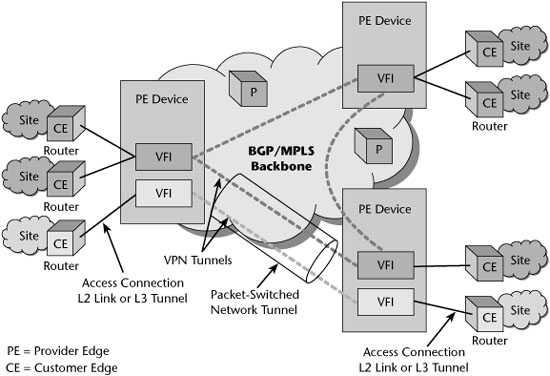
VFI entities implemented in different provider edge devices on the same service provider network and belonging to the same VPN are interconnected via VPN tunnels. As mentioned earlier in this chapter, a VPN tunnel is a virtual link between two entities that belong to the same VPN. This virtual link is implemented by means of adding an encapsulation header to each forwarded packet, and that header is understood by the packet-switched network backbone in such a way that the encapsulated traffic can be forwarded from the packet-switched network source entity to the packet-switched network destination entity. The source entity is responsible for adding the encapsulation header, and the destination entity is responsible for removing it. Multiple VPN tunnels established between the same two provider edge devices are often multiplexed in a provider edge–to–provider edge packet-switched network tunnel and transparently carried over the packet-switched network’s provider core devices.
The customer site is a local private network—that is, a set of communication devices that do not use a shared backbone to communicate with each other. The edge devices of a site, the customer edge routers, are connected to one of the service provider’s provider edge devices via an access connection or attachment circuit through the access network. An access connection in this context is a dedicated Layer 2 connection, such as an ATM virtual circuit, a Frame Relay data link connection identifier (DLCI), a PPP connection, an Ethernet interface, or a virtual LAN. It could also be a Layer 3 tunnel, such as an IPsec security association over the Internet. The customer edge–to–provider edge access connection is configured to be associated with the specific VFI in the provider edge, depending on which VPN the site belongs to.
Layer 3 VPNs are implemented in two ways:
- RFC 2547 (BGP MPLS) VPNs—RFC 2547 is an IETF informational document that describes BGP MPLS. RFC 2547bis—the second version of RFC 2547—is an Internet Draft. RFC 2547bis VPNs are also known as BGP MPLS VPNs because BGP is used to distribute VPN routing information across the provider’s backbone and MPLS is used to forward VPN traffic from one VPN site to another. RFC 2547bis multiplexes many VPN routes through a single BGP system. In this approach, customer routing is terminated at the provider edge.
- Virtual router VPNs—With these types of VPNs, each virtual router runs an instance of a routing protocol that is responsible for disseminating VPN reachability information between virtual routers. In this model, customer routing is extended across the provider network.
The following sections describe these two types of Layer 3 VPNs in detail.
RFC 2547 (BGP MPLS) VPNs
IP VPNs based on RFC 2547 are becoming increasingly popular. As shown in Figure 9.23, they use a combination of BGP and MPLS to pass IP traffic through an MPLS core. Offering this type of VPNs requires a provider to configure MPLS on all core and edge routers. Furthermore, all provider edge routers need to have Multiprotocol BGP (MP-BGP) sessions established between them to communicate VPN information. The provider edge routers store the routing updates from each customer’s customer edge router in what is termed a virtual routing forwarding (VRF) instance; simply put, it is a routing table populated with VPN routes.
Figure 9.23 The RFC 2547bis model
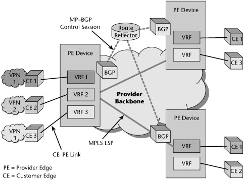
Because there may be a great number of provider edge routers in a network, carriers might also need to configure BGP route reflectors to simplify the internal BGP mesh. Route reflectors reduce the size of the internal BGP mesh. Route reflector clients propagate routes up to the route reflectors, which, in turn, send the routes to other route reflector clients. Route reflectors are useful in partitioning total routing table space across multiple devices. This allows the route reflector clients to receive only routes they need—not all the routes.
Each customer edge router has its own VRF on the provider edge. The customer advertises all routes associated with that location to the provider edge. When all the provider edge routers that connect to a particular customer have the customer’s routing information in a VRF, the provider edge routers exchange information by using MP-BGP. These routes and the corresponding VRFs make up the customer VPN.
To the customer, from a routing perspective, the customer edge routers appear as if they are connected via a traditional VPN. The customer can view the routing table on the customer edge router and see routes to remote sites, just as it would with a traditional VPN. The routing adjacencies formed are between the customer edge and the provider edge, not the customer edge and the customer edge. The customer edge has one interface to the MPLS cloud, and the MPLS provides full or partial meshing with the customer edge router attached to the network.
One of the benefits of Layer 3 MPLS VPNs is that the provider handles all the meshing and can provide any-to-any connectivity over a multitude of interface types. Previously, if a customer wanted to mesh its remote locations, it had to purchase leased lines and build a mesh of permanent virtual circuits (PVCs). The routing architecture and propagation of routes was up to the customer; the provider only ensured connectivity. With Layer 3 MPLS VPNs, all that is required is the advertisement of the routes to the provider edge, and the provider handles the rest. The only drawback to this solution is that the provider may not have the geographic footprint to reach all the customer locations; it can be cost-prohibitive for the customer to purchase a local loop to the nearest provider edge router in the provider’s POP. This is a limiting factor with MPLS deployment, especially for organizations that have international locations.
Virtual Router VPNs
The objective of a Layer 3 virtual router VPN, which is currently an IETF Internet Draft, is to provide per-VPN routing, forwarding, QoS, and service management capabilities. This VPN service is based on the concept of a virtual router, which has exactly the same mechanisms as a physical router and, therefore, can inherit all existing mechanisms and tools for configuration, deployment, operation, troubleshooting, monitoring, and accounting. Multiple virtual routers can exist in a single physical device, and virtual routers can be deployed in various VPN configurations.
Direct virtual router–to–virtual router connectivity can be configured through Layer 2 links or through a variety of tunnel mechanisms, using IP- or MPLS-based tunnels. Also, multiple virtual routers can be aggregated over a backbone virtual router. This architecture accommodates various backbone deployment scenarios, including situations in which the VPN service provider either owns the backbone or obtains backbone service from one or more other service providers.
As shown in Figure 9.24, a VPN customer site is connected to the provider backbone by means of a connection between a customer edge device—which can be one or more hosts and/or routers—and a virtual router. Customer edge devices are preconfigured to connect to one or more virtual routers. Multiple virtual routers may coexist on the same service provider edge device or provider edge. Customer edge devices can be attached to virtual routers over any type of access link (e.g., ATM, Frame Relay, Ethernet, PPP) or IP tunneling mechanisms (e.g., IPsec, L2TP, or GRE tunnels). Customer edge sites can be statically connected to the provider network via dedicated circuits or can use dialup links. Routing tables associated with each virtual router define the site-to-site reachability for each VPN. The internal backbone provider routers are not VPN aware and do not keep VPN state.
Figure 9.24 Virtual router VPNs
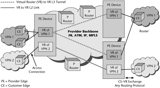
In general, the backbone is a shared network infrastructure that represents either a Layer 2, ATM, or Frame Relay network; an IP network; or an MPLS network. Not all VPNs existing on the same provider edge are necessarily connected via the same backbone, so a single provider edge can be connected to multiple backbones. Individual virtual routers on the provider edge may also connect to multiple backbones. Thus, a single VPN can be built from multiple transport technologies in the virtual router architecture.
Virtual routers have independent IP routing and forwarding tables, and they are isolated from each other. This means that two virtual routers on a provider edge can serve two different VPNs that may have overlapping address space. The addresses need only be unique within a VPN domain. A virtual router has two main functions: constructing routing tables for the paths between VPN sites, by using any routing technology (such as OSPF, RIP, or a border gateway protocol), and forwarding packets to the next hops within the VPN domain.
From a VPN user’s point of view, a virtual router provides the same functionality as a physical router. Separate routing and forwarding capabilities provide each virtual router with the appearance of a dedicated router that guarantees isolation from the traffic of other VPNs while running on shared forwarding and transmission resources. To the customer edge access device, the virtual router appears as a neighbor router in the customer edge–based network.
Three main virtual router deployment scenarios can be used for building VPNs: virtual router–to–virtual router connectivity over a Layer 2 connection, virtual router–to–virtual router connectivity tunneled over an IP or MPLS network, and aggregation of multiple virtual routers over a backbone virtual router to provide connectivity over a Layer 2 IP or MPLS network. These virtual router deployment scenarios can coexist on a single provider edge or within a single VPN.
RFC 2547 VPNs Versus Virtual Router VPNs
Table 9.2 compares the RFC 2547 VPN and virtual router VPN architectures.
Table 9.2 Summary of RFC 2547 and Virtual Router VPNs

The standards debate is ongoing, with high-profile companies on both sides of the argument. For now, the choice of a network-based VPN implementation is up to the provider. All these IP VPN services are more complicated to configure and require more attention from both carriers and customers than Frame Relay, private-line, or ATM services. Without any application or architectural triggers for the customer to move to IP VPN service, the shift may be very gradual.
Layer 2 VPNs
Carriers need to continue to benefit from legacy services such as TDM private lines, Frame Relay, and ATM while they introduce new Ethernet metro-transport and Ethernet access services. They need a common edge infrastructure that supports both new and legacy services and allows all the services to seamlessly communicate. To accomplish this goal, most carriers are planning to simplify their network infrastructures over a common MPLS core and introduce MPLS-based services.
MPLS was first deployed in the core of carrier networks to enhance the performance and capabilities of connectionless IP routing. Today, there is increased interest in MPLS Layer 2 VPN services. With MPLS Layer 2 VPN services, carriers can transport protocols such as SNA, DECnet, or IPX and keep legacy TDM private lines as well as Frame Relay and ATM services. With Layer 2 VPNs, the provider forwards packets based on Layer 2 information or port information. It emulates Layer 2 WAN or LAN connectivity between customer sites. In this case, the customer is responsible for the Layer 3 routing. Layer 2 MPLS VPNs are identical to private network VPNs in that the customer attaches its customer premises router to the MPLS cloud via traditional Layer 2 circuits and builds a Layer 3 routing topology over the provisioned circuits. The management of the routing is handled by the customer in the same fashion as it would be with a traditional private VPN.
In a Layer 2 VPN solution, there is no exchange of routing information between the provider edge and the customer edge. The IP/MPLS service provider core network transports customer Layer 2 frames from ingress provider edge to egress provider edge. The VPN tunnels that transport this traffic between provider edges are called pseudo-wires, as they emulate the behavior of a connection or wire over a connectionless infrastructure. The provider edges implement Layer 2 VFIs that forward the customer traffic based on Layer 2 information (e.g., ATM virtual path identifiers and virtual circuit identifiers, or Ethernet MAC addresses, or Frame Relay DLCIs). This is beneficial for organizations that need legacy protocol support and those that feel they can efficiently and cost-effectively manage their own routing environment. They are, in effect, purchasing bandwidth, not the additional services offered by a Layer 3 MPLS VPN. Customers still have the PVC mesh, provisioning, and routing issues, as before, and there may be limitations on what interfaces a carrier will support. Carriers that are evaluating Layer 2 VPNs are challenged by the interconnectivity issues associated with Layer 2 VPNs. Support for any-to-any connectivity over Layer 2 MPLS backbones is not widely deployed by any of the major carriers. In most instances, the customer edge routers require common access types, such as Frame Relay–to–Frame Relay or ATM-to-ATM. Ultimately, however, Layer 2 MPLS VPNs will allow customers to attach any Layer 2 access circuit to the MPLS cloud, allowing for diverse and cost-effective interface options.
Multiple Layer 2 VPN service models are being analyzed in the industry and by the Provider Provisioned Virtual Private Networking (PPVPN) working group and the Pseudo-Wire Emulation Edge-to-Edge (PWE3) working group. The PPVPN group is working on the Kompella draft, named after Cureda Kompella. The Kompella draft makes use of BGP to allow provider edge routers to communicate with one another about their customer connections. The PWE3 group is working on a draft named the Martini draft, after Luca Martini. The Martini draft makes use of the Label Distribution Protocol (LDP) between provider edge routers. Two of the most important Layer 2 VPN models, VPWS and VPLS, are described in the following sections.
VPWS
VPWS VPNs are also known as point-to-point pseudo-wires. A pseudo-wire emulates a point-to-point link and provides a single service perceived by its user as an unshared link or circuit of the chosen service. Using encapsulated pseudo-wire tunnels, customers’ sites can be connected via point-to-point circuits as if they were using their own private leased lines (see Figure 9.25). VPWS VPNs support traffic types such as Ethernet, ATM, Frame Relay, SDH/SONET, and TDM. VPWS provides a mesh of point-to-point customer edge–to–customer edge Layer 2 connections over a packet-switched network. The provider edge does the mapping between the attachment circuit and the pseudo-wire.
Figure 9.25 VPWS
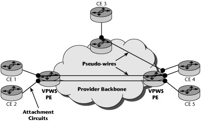
VPWS is seen largely as an appropriate approach for point-to-point connection-oriented services, such as ATM, Frame Relay, and point-to-point Ethernet. For multipoint-to-multipoint connectionless services such as Ethernet and VLANs, VPLS is required.
VPLS
A number of vendors have adopted the VPLS approach, and deployments of VPLS are mushrooming worldwide. VPLS is a growing solution for providing Ethernet services. It combines the benefits of Ethernet and MPLS for both customers and carriers.
VPLS offers at Layer 2 what IP VPNs offer at Layer 3: a service with multipoint connectivity (see Figure 9.26). The main difference is the interface used between the customer edge equipment and the provider edge equipment. With IP VPNs, customer edge equipment is IP routers, whereas with VPLS, it can be an Ethernet bridge, a switch, a hub, or a router, allowing non-IP traffic as well as IP traffic to be exchanged between sites. Apart from this essential difference, MPLS Layer 2 VPNs and Layer 3 VPN-based approaches are very similar in other areas. Both share the same common MPLS protocols and the underlying IP/MPLS infrastructure. In the past, these services were most commonly delivered on TDM, Frame Relay, and ATM networks. VPLS is one of the most innovative and easily manageable ways of providing Ethernet MPLS VPNs. Each customer location is attached to a node on the MPLS network. For each customer or VPN, a full mesh of logical point-to-point connections is set up over the backbone MPLS network. This allows a customer location to have direct visibility to every other location belonging to that customer.
Figure 9.26 VPLS
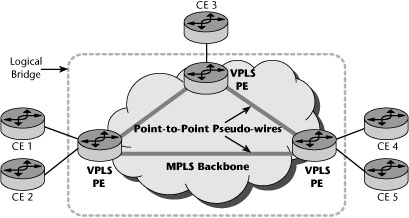
Unique MPLS labels are used to segment one customer’s traffic from another’s and to segment one service from another. This segmentation allows a customer to acquire a bundle of services from its provider, each of which is tailored for the end application. For example, a customer’s bundle could comprise VoIP, Internet access, and maybe two or more VPN services. The first VPN service could be to provide broad data connectivity between all corporate locations, accessible to all employees. The second VPN service could be restricted to some financial transactions conducted between a subset of locations. Each of these services would be uniquely configured over VPLS, thus allowing them to have unique quality and security attributes.
VPLS provides logical LAN bridging or switching functions over a packet-switched network. The provider edge performs virtual bridging or switching for LAN-attached customer edge nodes. VPLS supports both point-to-multipoint and multipoint-to-multipoint service using PWE3. PWE3 specifies the encapsulation, transport, control, management, interworking, and security of services emulated over packet-switched networks.
The benefits to carriers of combining Ethernet and MPLS are numerous. Carriers immediately benefit from the lower capital expenditure required for deploying Ethernet infrastructure. However, a simple Ethernet switched network has limitations on service scalability due to VLAN ID restrictions as well as limitations on reliability (e.g., Spanning Tree Protocol does not scale well). These limitations are solved by MPLS, which offers a portfolio of solutions that provide massive scalability and multiple reliability options and also bring other benefits. For example, MPLS’s dynamic signaling is instrumental in providing quicker changes and reconfigurations of service. Its traffic engineering capabilities allow providers to support service-level guarantees across the entire network. Thus, it not only meets their needs for scalability and reliability but also provides operational advantages that can further reduce expenditures.
The advent of the Internet and the resulting productivity gains spurred by the adoption of new technologies are leading to a demand for increased bandwidth and services. Corporations are demanding customized services at greater bandwidth, and consumers are looking for services such as broadband connectivity and VOD. Carriers have to balance the demands of their target markets with the realities of their business. Traditional technologies (such as ATM and SDH/SONET), while being familiar, simply do not match the vision that carriers have for their networks. They are built on expensive infrastructure that cannot scale without large investments. Moreover, the complex management and multiple handoffs between all these technologies cause significant operating overhead. The market opportunity for Ethernet services is clear and exists today. Numerous early adopters have been successful in deploying these services. Carriers are facing a challenge in how to respond to these market dynamics. VPLS with an Ethernet infrastructure can present an optimal solution for carriers to roll out new services profitably. The benefits from reduced capital and operating expenditures add up quickly to improve the bottom line. In addition, the ability to leverage existing networks ensures carriers that the investments made in older technologies can be preserved and that more returns can be generated from them. There are, however, potential disadvantages associated with the use of Ethernet in MANs and WANs. The biggest concern is the lack of QoS capabilities, leading some industry observers to view Ethernet solutions as one of throwing bandwidth at the problem and therefore a short-term strategy at best.
VPN Security
Security is very important to the proper operation of VPNs. The following sections describe the available security mechanisms, including firewalls; authentication, authorization, and accounting (AAA); encryption; and digital certificates.
Firewalls
A firewall is typically defined as a system or a group of systems that enforces and acts as a control policy between two networks. It can also be defined as a mechanism used to protect a trusted network from an untrusted network—usually while still allowing traffic between the two. All traffic from inside to outside and vice versa must pass through the firewall. Only authorized traffic, as defined by the local security policy, is allowed to pass through it. The system itself is highly resistant to penetration. A firewall selectively permits or denies network traffic.
There are several variations of firewalls, including the following:
- A firewall can use different protocols to separate Internet servers from internal servers.
- Routers can be programmed to define what protocols at the application, network, or transport layer can come in and out of the router—so the router is basically acting as a packet filter.
- Proxy servers can separate the internal network users and services from the public Internet. Additional functions can be included via proxy servers, including address translation, caching, encryption, and virus filtering.
The term virus broadly refers to a program designed to interfere with computers’ normal operations. The term also can be used more narrowly to refer to malicious software programs that move from one file to another and can be transmitted to other PCs via an infected file. They generally don’t seek out the Internet or e-mail to spread.
Another type of malware is a worm. Worms make use of a LAN or the Internet (especially via e-mail) to replicate and forward themselves to new users. Many worms target humans, not software.
Finally, a Trojan horse hides within another program or file and then becomes active when someone opens the unwitting host.
A big part of administrating security involves reducing the threat of malware. The fact that we can deploy malware detection and removal technologies on a proxy server is very attractive.
Authentication, Authorization, and Accounting
An important aspect of security is the authentication of users and access control, which is commonly handled by an AAA server. An AAA server is a network server used for access control. Authentication identifies the user, authorization implements policies that determine which resources and services a valid user may access, and accounting keeps track of time and data resources used for billing and analysis. The AAA server, also called 3A software, typically interacts with a network access server (NAS) and gateway servers, as well as with databases and directories that contain user information.
RADIUS, the current standard by which devices or applications communicate with an AAA server, is an AAA protocol for applications such as network access or IP mobility. This UDP-based protocol is intended to work in both local and roaming situations and is considered suitable for high-volume service control applications, such as regulation of dialup or VPN services. Increased use of RADIUS is occurring due to the introduction of 802.1X port security (discussed in Chapter 15, “WMANs, WLANs, and WPANs”) for wired and wireless LANs. In fact, Microsoft has included 802.1X security in Windows TCP/IP, and every enterprise PC might require authentication before being granted access to the LAN.
RADIUS servers are designed to block unauthorized access by remote users, and they rely on authentication schemes such as Challenge Handshake Authentication Protocol (CHAP), which means there’s a back-and-forth dialog to verify a user’s identity. In fact, RADIUS makes use of CHAP, which uses a three-way handshake to periodically verify the identity of the peer throughout the connection. The server sends a random token to the remote workstation. The token is then encrypted, using the user’s password, and sent back to the server. The server performs a lookup to see whether it recognizes the password. If the values match, the authentication is acknowledged; if the values do not match, the connection is terminated. Because a different token is provided each time a remote user dials in, CHAP provides robust authentication.
A newer protocol, called DIAMETER, serves as a replacement for RADIUS. DIAMETER is also an AAA protocol for the same applications of network access and IP mobility. The major change is that DIAMETER extends RADIUS to provide AAA services to new access technologies.
Encryption
The best way to protect electronic data is to use encryption—that is, to encode the data so as to render a document unreadable by all except those who are authorized to have access to it. Encryption and decryption are performed by using a cipher, which is an algorithm, or a series of well-defined steps that can be followed as a procedure. The content of an original document is referred to as plaintext. When encryption is applied to the document, the plaintext is scrambled, through the use of an algorithm and a variable, or key; the result is called ciphertext. The key is a randomly selected string of numbers. Generally, the longer the string, the stronger the security.
Although encryption may ensure privacy, other techniques are required for full communications security, including a message authentication code or digital signatures, both used to verify the authenticity and integrity of the message. The message authentication code is a tag, or short piece of information, used to authenticate a message. Using a secret key and an arbitrary-length message, a message authentication code algorithm calculates a hash value, which protects the message’s integrity and authenticity by allowing those who also have the secret key to detect any changes that may have been made to the message content. The same secret key is used to both generate and verify the message authentication code values. Digital signatures, on the other hand, use two complementary algorithms: one for signing the message and the other for verification. Digital signatures rely on public key cryptography (discussed later in this chapter).
There are two major categories of encryption algorithms: symmetric and asymmetric.
Symmetric Encryption
In symmetric encryption, the sender and the receiver use the same key or machine setup. There are two approaches to encoding data using symmetric encryption: block cipher and streaming cipher. With the block cipher approach, the algorithm encodes text in fixed-bit blocks, using a key whose length is also fixed in length. With the streaming cipher approach, the algorithm encodes the stream of data sequentially, without segmenting it into blocks. Both of these techniques require a secure method of reexchanging keys between the participants.
Symmetric encryption algorithms include the following:
- Data Encryption Standard (DES)—DES, which was developed in the 1970s, is very popular in the banking industry. It is a block cipher that encodes text into fixed-bit blocks (typically 64 bits), using a 56-bit key. DES has been replaced by Advanced Encryption Standard (AES).
- Triple DES (3DES)—3DES is 168-bit encryption that uses three 56-bit keys. 3DES applies the DES algorithm to a plaintext block three times.
- Rivest Cipher 4 (RC4)—RC4 is a streaming cipher technique; a stream cipher adds the output of a pseudorandom number generator bit by bit to the sequential bits of the digitized plaintext.
- Blowfish—Blowfish is a 64-bit block code that has key lengths of 32 bits to 448 bits. Blowfish is used in more than 100 products and is viewed as one of the best available algorithms.
- International Data Encryption Algorithm (IDEA)—IDEA, developed by ETH Zurich (www.ethz.ch), is free of charge for noncommercial use. It is viewed as a good algorithm and is used in Pretty Good Privacy (PGP) and in Speak Freely, a program that allows encrypted digitized voice to be sent over the Internet.
- Twofish—Twofish, developed by Bruce Schneier of Counterpane Internet Security (www.counterpane.com), is very strong, and it was one of the five initial candidates for AES.
- Advanced Encryption Standard (AES)—AES was adopted by the National Institute of Standards (NIST; www.nist.gov) in November 2001 after a five-year standardization process.
According to NIST, it would take 149 trillion years to crack the U.S. government’s AES, which uses the Rijndael algorithm and specifies three key lengths—128 bits, 192 bits, and 256 bits. In comparison, DES, which uses a 56-bit key, would take only a matter of hours using a powerful computer, but, of course, this is totally dependent on the speed of the hardware used for cracking the code; a typical desktop PC would require much more than a few hours to crack a 56-bit DES key.
Asymmetric Encryption
Key encryption requires a secure method for exchanging keys between participants. The solution to key distribution came, in 1975, with Diffie and Hellman’s public key cryptography scheme. This permits the use of two keys, one of which can be openly published and still permit secure encrypted communications. This scheme later became known as asymmetric key cryptography (also called public key encryption [PKE]).
Asymmetric cryptography can be used for authentication. After encrypting a signature by using a private key, anyone with access to the public key can verify that the signature belongs to the owner of the private key. As shown in Figure 9.27, the following are the steps in PKE:
1. User A hashes the plaintext.
2. User A encrypts the plaintext with user B’s public key and encrypts the hash value with user A’s private key.
3. User B decodes the ciphertext with user B’s private key.
4. User B decodes the hash value with user A’s public key, thereby confirming the sender’s authenticity.
5. User B calculates the hash value of the just-encrypted plaintext.
6. User B compares the decrypted hash value with the value calculated locally, thereby confirming the message’s integrity.
Figure 9.27 Encryption and authentication
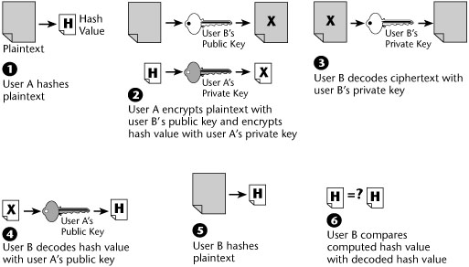
Public key management involves the exchange of secrets that both ends use to produce random short-term session keys for authenticating each other. It is a method of encrypting data by using two separate keys or codes. The sender uses a public key generally provided as part of a certificate issued by a CA to scramble data for transmission. The receiver then uses the corresponding private key to decrypt the data upon receipt. The CA issues certificates that contain data about individuals or enterprises that has been verified to be authentic (although not all public CAs do this). In essence, the CA vouches for the authenticity of other parties so that their communications are secured.
Message authentication verifies the integrity of an electronic message and also verifies that an electronic message was sent by a particular entity. Before an outgoing message is encrypted, a cryptographic hash function—which is like an elaborate version of a checksum—is performed on it. The hash function compresses the bits of the plaintext message into a fixed-size digest, or hash value, of 128 or more bits. It is then extremely difficult to alter the plaintext message without invalidating the hash value.
Message authentication mechanisms include Message Digest-5 (MD5) and Secure Hash Algorithm-1 (SHA-1). MD5 hashes a file of arbitrary length into a 128-bit value. SHA-1 hashes a file of arbitrary length into a 160-bit value; it is more processor intensive, but it renders greater security.
Public key management provides a secure method for obtaining a person’s or an organization’s public key, with sufficient assurance that the key is correct. There are three main public key algorithms: RSA (named for its creators, Rivest, Shamir, and Adelman), Diffie-Hellman, and PGP. RSA is the oldest of the three algorithms, and its security derives from the difficulty of factoring the product of two large prime integers. Diffie-Hellman is used mostly for exchanging keys; its security rests on the difficulty of computing discrete algorithms in a finite field, generated by a large prime number. PGP (www.pgp.com), which was created in 1991, is one of the most popular PKE schemes.
Public Key Infrastructure
Without a functioning universal public key infrastructure (PKI), we cannot reliably and easily acquire certificates that contain public keys for persons or organizations we want to communicate with. One of the biggest hurdles e-commerce companies face is confirming the identity of the parties involved. Ensuring identity requires an encrypted ID object that can be issued by a mutually trusted third party (i.e., a CA) and then verified and accepted by a user’s browser. Personal digital IDs contained in the user’s browser accomplish this. Historically, these client certificates have been used to control access to resources on a business network, but they can also contain other user information, including identity discount level or customer type. The user’s browser reads the server certificate, and if it’s accepted, the browser generates a symmetric session key, using the server’s public key. The server then decrypts the symmetric key, which is then used to encrypt the rest of the transaction. The transaction is then signed, using the user’s digital ID, verifying the user’s identity and legally binding the user to the transaction.
PKI is a system that provides protocols and services for managing public keys in an intranet or Internet environment; it involves distributing keys in a secure way. PKI secures e-business applications such as private e-mail, purchase orders, and workflow automation. It uses digital certificates and digital signatures to authenticate and encrypt messages. It permits the creation of legally verifiable identification objects, and it also dictates an encryption technique to protect data transmitted over the Internet.
Usually, PKI involves client software, server software such as a CA, hardware (e.g., smart cards), and operational procedures. Using his or her private key, one user digitally signs a message, and the receiver, using the public key contained in the sender’s certificate, issued by a CA within the PKI, can check that signature. In this fashion, two or more users can establish confidentiality, message integrity, and user authentication without having to exchange any special information in advance. PKI systems used in the enterprise are generally closely linked to the enterprise directory system, where each employee’s public key is often stored, along with his or her general contact information. The leading directory technology is LDAP, which is discussed in Chapter 10.
Standards are absolutely vital to proper PKI operation, given that there is a certificate hierarchy composed of at least several computers and often more than one organization, using interoperating software from different sources. The group responsible for developing standards in this area is the IETF PKIX working group (www.imc.org/ietf-pkix). This group’s purpose is to develop the Internet standards needed to support an X.509-based PKI. (X.509 is discussed in the next section.)
Overall, the market for commercial PKI operations has not bloomed as its pioneers imagined. Too many differences in enacted laws and regulations, not to mention technical and operational problems, have slowed progress tremendously.
There are some alternatives to PKI, including Web of Trust, Simple Public Key Infrastructure, and Robot Certificate Authorities.
The Web of Trust scheme makes use of self-signed certificates and a third party that attests to those certificates. Two examples of the Web of Trust are GNU Privacy Guard (GPG) and PGP, which has been extensively used in e-mail and is widely deployed.
Simple PKI (SPKI) came out of three independent efforts to overcome the growing popularity of PGP’s Web of Trust and the complexities of X.509. With SPKI, users and systems are bound directly to keys, using a local trust model, somewhat like the Web of Trust, but with the addition of authorization.
As the name suggests, Robot Certificate Authorities (Robot CAs) are automated programs that validate certain aspects of a public key’s validity and then sign it to attest that those aspects are indeed valid. The common aspects validated include the following: the use of the key is current, the holder of the destination e-mail address is aware that his or her key is published, and a secret key corresponding to the public key is in possession of the holder of the e-mail address. At this point, the most successful PKI implementations are in government.
Digital Certificates
Digital certificates, based on the ANSI X.509 specification, have become a de facto Internet standard for establishing a trusting relationship by using technology. X.509 comes from the X.500 specification on directory services, which serves as an electronic phonebook, allowing enabled applications to look up included entities. Each entity has an identifying record or certificate, and that certificate follows the ITU X.509 recommendation. Using digital certificates is a method for registering user identities with a third party, a CA (such as Entrust or VeriSign). A digital certificate binds a user to an electronic signature that can be trusted like a written signature and includes authentication, access rights, and verification information. CAs prepare, issue, and manage the digital certificates, and they keep a directory database of user information, verify its accuracy and completeness, and issue the electronic certificates based on that information. A CA signs a certificate, verifying the integrity of the information in it.
By becoming their own digital CAs, service providers can package electronic security with offerings such as VPN and applications services. Server certificates ensure Internet buyers of the identity of the seller’s Web site. They contain details about the Web site, such as the domain name of the site and who owns it. Third parties, such as Thawte (www.thawte.com), then guarantee this information. Sites with server certificates post the CA, and Internet browsers accept their certificates for secure transactions.
There are still many security developments to come, especially with the constant introduction of new networking technologies and systems. Standards need to be defined and formalized for the likes of the various IP services and wireless/mobile networks before e-commerce will truly be able to function with the security that it mandates. For now, these are the types of mechanisms necessary to ensure that your data remains with you.