
5 Building the Room
Contents
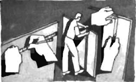
The Easy Way Out and Unique Solutions
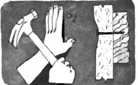
Tools and Materials for Electrical Work
Most communities require a permit to do plumbing or electrical work and in many cases require that the work be performed or supervised by a licensed electrician or plumber. These legal requirements are designed to ensure that the work is done properly and safely. Failure to comply with local laws is not recommended and can have a significant impact on your legal liabilities should any personal or property damage result.
Tools
The tools required to build a darkroom are common ones that you may already own. If you had to buy all of the best available tools, the total expenditure would be less than $300, which is reasonable considering how much you would have to pay to have the room built for you. If you are converting an existing room and plan on adding only wiring or plumbing, the cost will be even less.
Take it from someone who has learned the hard way: buy only the best tools. With reasonable care they will last a lifetime, whereas cheap tools probably won’t last through the first job. The tools shown on these pages are the standard ones required to do carpentry, plumbing, and electrical work.
Tools are generally classed as hand tools (powered only by the human hand), power hand tools (operated by hand but powered by a motor), and power tools (benchmounted and powered by a motor). The tools demonstrated in this book are from the first two categories; large power tools are not necessary.
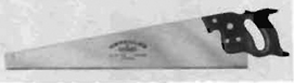
Hand Saw. These come in two kinds: crosscut (used to cut across the grain of the wood) or rip (used to cut along the grain).
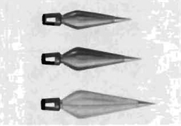
Plumb Bob. Suspended on a string, these are used to determine a perfect vertical line. When installing framing, paneling, and so forth, they will ensure that the verticals are accurate.

Pliers. Pliers can be used for holding, turning, bending, or crushing. The best kind are slip-joint pliers that adjust to handle either larger or smaller pieces.
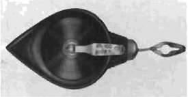
Chalk Line. When the string is pulled out of the holder it is covered with chalk dust. If you hold both ends down and snap the taut string, it will snap against the floor or wall and leave a line of chalk. This is a simple way to lay out the floorplan on the basement floor, or to indicate where pipes or counters are to be run along a wall. You can also use a piece of string and chalk, snapping it against the floor in the same manner, which works just as well (although a bit messier).
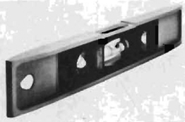
Level. These are used to determine if something is level in either the vertical or horizontal directions. A curved fluid-filled tube with an air bubble in it indicates when the level (and whatever it happens to be held against) is level and, if not, what direction it is tilted.
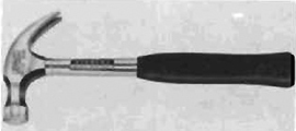
Hammers. The best hammer for carpentry work is the curved claw model that enables you to drive a nail and then pull it out using the other end.
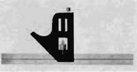
Combination Square. Combines the functions of a ruler, square, and level in one unit. Ideal for general purpose work, and its small size makes it easy to work with.
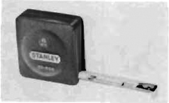
Tape Measure. You can buy several different types of rulers, including the folding zig-zag ruler or the tape ruler shown here. Most types will suffice for general construction work, but this one is slightly more convenient, since it is small and comes in lengths ranging from 6’ to many hundreds of feet.
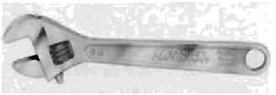
Adjustable Wrench. Rather than buy a whole set of open-end wrenches, buy one of these. They come in various sizes, and the one you select should be based on the maximum size of nut you expect to encounter. Because the largest nut is most likely to be in the plumbing, a wrench for working on plumbing fittings should have jaws that open at least 1 1/2”.
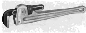
Pipe Wrench. Used primarily to fasten and unfasten threaded steel pipe.
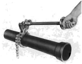
Chain Wench. Used to twist large drain, waste, or vent pipes in sewer systems.
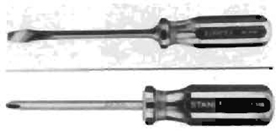
Screwdrivers. These come in two types, slot-headed and Phillips, for two different kinds of screw heads. They are easy to tell apart: the Phillips screw has crossed slots, and the other has a single straight slot running across the screw head. You should have a variety of sizes of screwdrivers. The head should fit snugly into the slot of the screw or you will damage the screw, making it difficult to remove.
![]()
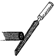
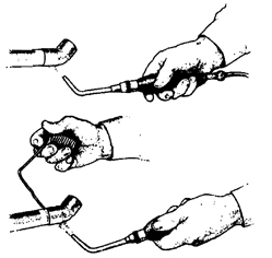
Tubing Bender. Used to bend copper tubing so that the walls do not collapse and restrict the flow.
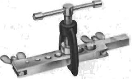
Flaring Tool. Used in flaring the ends of copper tubing to be used in plumbing and incoming water lines; simplifies the installation and eliminates the need for using a torch and solder.
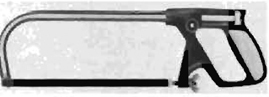
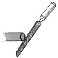
Hacksaw. This tool is very handy for cutting copper or plastic plumbing pipe. It can also be used to cut cast-iron pipe or ventilating duct.
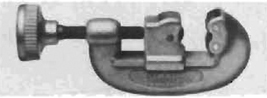
Tubing Cutter. Designed to make even, smooth cuts in copper pipe or tubing. Makes working with pipe easy. As the tool is revolved around the tube, the blade gradually cuts deeper and deeper until the piece you want drops off.
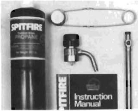
Propane Torch. If you choose to use soldered joints in your plumbing system, you will need a torch to solder the joints.
Power Tools
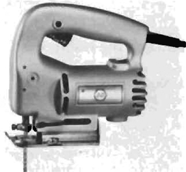
Sabre/Bayonet Saw. If you plan on buying only one power tool, this should be it. It is by far the most versatile tool available for cutting wood, plastics, and metal. Many styles of blades are available, ranging from fine wood scroll blades, to blades that cut cardboard, to blades that cut sheet steel. The narrow blades allow you to drill a starter hole in a wall and then cut out an opening without using additional tools.
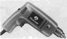
Drill. The power drill is usually a standard tool in the home workshop. Its basic function is to drill holes, but special attachments can be added to grind, polish, and sand. Slightly more expensive models have reversing motors and variable speed controls, which are especially useful because they allow you to start a hole with a low speed thus giving you more control. For darkroom building, a hand brace and bit will suffice if you don’t already have a power drill.
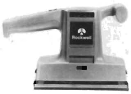
Sander. The power sander can save you hours of work and is certainly a good investment.
Installing Partitions
Building the Room Itself
If you are planning to install the darkroom in a large space, such as a basement or garage, the first step is usually to partition the darkroom off. If this is not done, it will be much more difficult to control both the cleanliness and the light-tightness of the space. It is relatively easy to make partitions; building door frames and hanging doors can be greatly simplified by buying set-up units.
There are two kinds of partitions, load-bearing and nonbearing. If you have to move an existing partition to accommodate the new ones for your darkroom, you should know which kind it is. A load-bearing wall supports part of the weight of the house, and its removal can cause serious problems in upstairs floors and ceilings. A nonbearing wall can be removed without replacing the sup port, as you would have to do with a bearing wall; however, even nonbearing walls may contain pipes or electrical wiring that must be rerouted. Study the wall carefully before deciding to move it. Wiring is fairly easy to reroute; plumbing is much more difficult. The detailed plans in this section deal with only the installation of new partitions that are nonbearing.
Wall partitions can be built with either 2x4 studs or 2 × 3s. The 2 × 4s are not significantly more expensive and do make a more stable wall, especially if cabinets and sinks will be mounted to it.
Always be sure to use well-seasoned lumber. If you use inexpensive green or wet lumber it will tend to twist and bend as it dries within the wall. This will crack the wall board and also make door frames and enlarger mounts move out of alignment. Specify “dry” lumber when ordering. For economy, always use the lowest grade of lumber suitable for your project. For wall studs, this would be “construction,” “standard,” or “utility” grades if your partitions are nonbearing, and “stud” grade if they are either load-bearing or nonbearing.
When preparing plans, remember that the measurements of lumber refer to the lumber before final cutting by the lumber yard. Therefore, a 2 × 4 is actually 11/2 × 3 1/2, and a 2 × 6 is actually 1 1/2 × 5 1/2.
Marking the Layout on the Floor
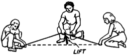
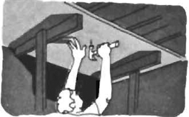
The first step in building the room is to mark the floor to show where the various walls and doors are to be placed. Using a chalk line, transfer the measurements from your layout to the floor. To make long straight lines with the chalk line, either drive nails at both ends so that the string can be stretched between them, or ask two friends to hold the ends down. With the string held tautly against the floor, lift it an inch or so straight up by grasping it in the middle of the run and let it snap back against the floor. A faint chalk line shows where the wall should be installed. You can measure off door openings against this line and indicate the markings on the floor.
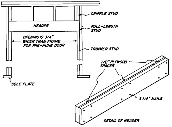
Door and Header Details
Marking a Chalk Line
Assembled Partition
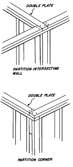
Joining Partitions
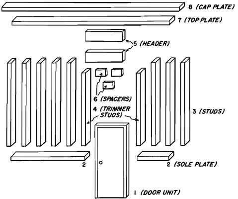
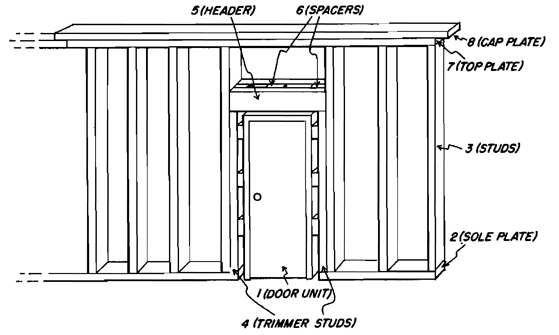
Partition Assembly. This two-part drawing shows a typical partition in both its assembled and unassembled state. If you are planning to build a light-trap, the construction would be identical, except the door and door frame would not be used. Instead, additional partitions would be built in the pattern selected for the light trap.
Begin the cutting and assembling by measuring off the sole plate (#2), cutting it to allow for a door opening if one is to be in that partition. The opening should be the width of the door frame, plus an additional 3/4” clearance needed for making adjustments when the frame is mounted into the wall.
Next cut the studs (#3) so that there are enough to be spaced every 16” along the sole plate. Cut a top plate (#7) to the same length as the sole plate (including the door opening).
Cut trimmer studs (#4) used to support the header over the door frame opening. These should be cut long enough to go from the top of the sole plate to 3/4” above the door frame.
Now cut two pieces of 2 × 6 (#5) for use as the header. Since they will be turned sideways to the other studs, their width will be too narrow unless spacing (#6) is used. If the wall is being constructed of 2 × 4s, an ideal “spacer” would be a piece of 1/2” plywood cut to size. Two pieces of 2 × 4 used sideways with a piece of this spacer in between equals the width of the 2 × 4 studs it will come in contact with. If your wall is being built of 2 × 6s to accommodate a sliding door, the header should be constructed of two pieces of 2 × 4 with spacers cut from another piece of 2 × 4 so that they are 2 1/4” wide.
After you cut and lay out all of the pieces on the floor, you can begin assembling the wall. Start by connecting the top and sole plates at either end to the full-length studs. Now put the door frame in place and nail in the trimmers and full-length studs, remembering to leave 3/4” clearance on top and sides. Now nail the header into place over the trimmers. Install the remaining studs, raise into place, and nail into the adjoining wall. Assemble the second and third walls in the same manner. Once they are raised into place, all of the walls should be connected with a cap plate (#8) as detailed in the figure.
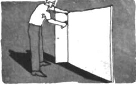
Hanging Doors
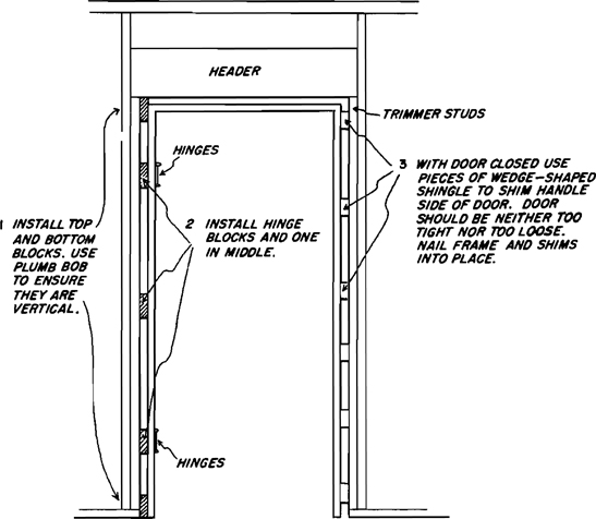
Installing Prehung Door Frame
When the walls have been raised into position and plumbed to ensure they are vertical, the door frame can be installed. Prehung (set-up) doors are available from most lumber yards, and since the door is already mounted to a frame, you do not have to install hinges, handles, lock sets, and so on. It is by far the easiest unit to use.
The first step is to cut five blocks half the width of the clearance left when the rough frame was assembled (3/8”). Nail one block to the top and one to the bottom of the rough opening on the side where the hinges are to be placed. Using a level, make sure they are exactly vertical. If they are not, you will have to plane the top or bottom one to make them so. Now install two blocks at the exact height of the door hinges to provide them with support, and place the remaining block halfway between them. Using the plumb bob, make sure that they are in line with the first two installed.
Install the door frame and nail it to these blocks using 3” nails. Once the hinge side of the door is nailed into place, the door can be closed and the other side of the frame shimmed into place, using old shingles that are wedge-shaped between the door frame and trimmer stud. Lightly tap them into place so the frame comes within 1/8” to 1/4” of the door itself. Be sure not to use too much pressure when inserting the shingles; that can cause the door frame to bow out, making the door stick. Use a level to ensure that the door frame is level on all sides. Open and close the door to make sure it is properly installed.
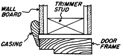
After the wall board has been installed, the door frame and the gap between it and the trimmer studs can be covered by casing, as shown in the figure.
Door Frame in Place
Casing
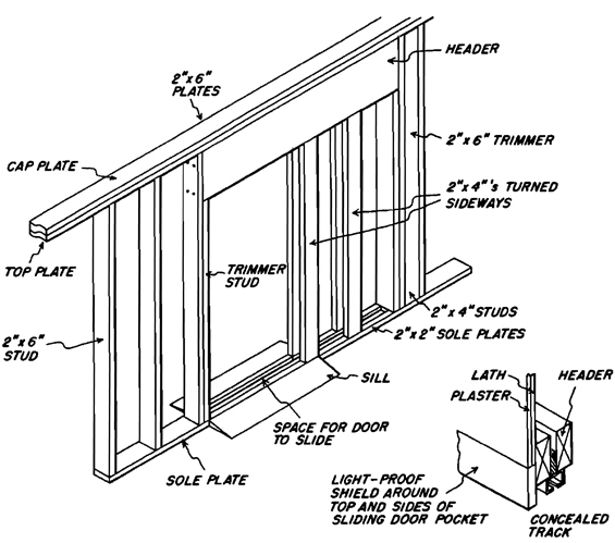
Pocket Sliding Door. If you are going to install a sliding door, the construction details are slightly different from those of a regular hung door. The wall must be thick enough to accommodate the door and its track within the partition itself, and there must be a space left in the door frame for the door to enter the partition when it is opened. The figure shows how the track and wall should be constructed. All steps are the same as for the regular wall, except the header is twice the width of the door and the space between the 2 × 2 sole plates must be wide enough to accommodate the door track. The door and track should be bought before assembling the wall, because track widths vary and you should be sure the opening you leave is wide enough.
In light-proofing the door, it is necessary to bring the 2 × 2 sole plates across the opening, which can create a hazard when entering or leaving the room. This hazard can be eliminated by cutting two wedge-shaped sills to be placed on either side of the sole plate.
Installing Backing
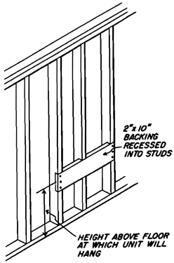
Backing. In some places, you will need support for heavy objects such as sinks, enlarger mounts, cabinets, and phones. Special reinforcement, called backing, should be installed at these locations. Use 2” × 10” board and notch the studs to accommodate it. The backing should be securely nailed to the studs and can span any distance, ranging from the distance between two studs to an entire length of wall. Its location should be indicated on your elevations, because it will be covered by wall board before the sinks and other pieces of equipment are attached to it. If you don’t remember where the backing is, you could have a problem locating it.
Installing Sheetrock®
Finishing and Painting
This step takes place after the plumbing and wiring have been installed. It is the final step in finishing the room and helps to make it more attractive and easy to keep clean. The materials used help to determine the quietness of the room, the ability to maintain a stable temperature inside it, and its degree of light-proofness and light-reflecting qualities.
Most rooms today are finished in drywall, which is a gypsum board consisting of a noncombustible core with a paper surface on front, back, and edges. It is easy to cut and install. Panels come in standard 4’ widths, and if you put your studs on 16” centers, one panel will cover four studs, from the middle of the first stud to the fourth. Some boards have beveled edges where sheets meet each other, allowing for easy filling of the cracks. If your panels have these bevels, they should be facing out. It is recommended that you use panels of either 1/2” or 5/8” thickness. The floor-to-ceiling height should be measured and the panels cut to fit and installed with nails made specifically for wallboard installation.
Courtesy United States Gypsum Company
1. Scoring. Place panel with ivory-colored side face up. Measure and mark panel size at opposite edges of panel. Line up straightedge with the marks. Hold straightedge firmly against the panel while scoring down through paper and part of panel core. Hold knife at slight angle away from straightedge to prevent cutting into straightedge.
2. Cutting. Break core of Sheetrock panel by snapping away from the scored face paper. Complete cutting by running knife through back paper.
3. Sanding Edges. Smooth all cut edges of panels with coarse sandpaper wrapped around a hand-size block of wood. Keep panel edges as square as possible.
4. Nail Attachment. For 1/4”, 3/8”, and 1/2” thick panels use 1 l/4”GWB-54 annular-ring nails. For 5/8” panels, use I 3/8” annular-ring nails. Space nails a maximum of 7” apart on ceilings, 8” on walls, and at least 3/8” from ends and edges of panels. Hold panel tight against framing and nail center of panel first, perimeter last. Leave a small dimple at the nailhead for filling with joint compound. Do not overdrive or countersink nails. This results in breaking the face paper or fracturing the core of the panel.
5. Ceilings. Apply ceilings first, with two people handling panels if possible. If you’re doing the job alone, make simple T-braces consisting of 2’ lengths of 1 × 4s nailed to 2 × 4 uprights that are 112” longer than the floor-to-ceiling height. Wedge T-braces between the floor and panel to support panel while nailing and assure firm contact with joists.
6. Walls. Carefully measure the locations and sizes of all openings in panels for fixtures. Cut with a keyhole saw. Fixture plates must cover cutouts completely. For horizontal application, apply the top panel first, tight against the ceiling panels. Stagger end-joints in adjacent rows. Use vertical application when ceiling height is over 8’ 2”, or if this results in fewer joints and less waste. Cut panels accurately so that they do not have to be forced into place.
7. Taping. Apply a large daub of joint compound across joint. Level with the surface of the channel formed by the tapered (or wrapped) edges of the board by drawing knife in direction of joint. Do not leave bare spots. Immediately apply reinforcing tape. Center tape over depression and firmly press into compound with joint-finishing kriife. Remove excess compound, but leave sufficient amount under tape for strong bond. Embed tape with thin layer of compound to fill taper flush with panel surface. Allow to dry.
To finish end joints (not paper wrapped), apply compound and center tape directly over joint. Do not overlap tape applied at tapered joints.
8. First Coat, Nails. Draw bare joint-finishing knife over nails. If metallic ring occurs, drive nail below surface. Fill all depressions with compound, level with surface. Apply compound with sweep of knife in one direction: wipe off excess compound in opposite direction, level with panel surface.
9. Second Coat. After taping coat has dried (at least 24 hours), smooth lightly with sandpaper to level surface. Apply compound, using larger knife, with compound extending 2” beyond taping coat. Feather both edges of compound, flush with face of panel, by applying pressure to the edge of the knife riding the panel. Allow to dry. Finishing the end (butt) joints is the same as for tapered-edge joints, except that the compound should cover a width of about 7”.
Apply second coat to nailheads.

10. Inside Corners. Use a joint-finishing knife to “butter” joint compound on both sides of the corner. Extend the compound slightly beyond the area to be covered by tape.
11. Inside Corners, Continued. Fold tape along center crease and lightly press into position. Firmly press both edges of tape into compound with finishing knife, removing excess compound. Leave enough compound under tape for strong bond.
12. Inside Corners, Second Coat. After joint compound has dried (at least 24 hours), apply second coat. Cover one side at a time, allowing first side to dry before applying compound to second side. Feather out onto face of panels beyond first coat.
13. Third Coat. Same procedure as No. 9 but feather about 2” beyond second coat. Apply third coat to nailheads. Allow to dry and sand lightly. Remove sanding dust from surface by wiping with a damp cloth.
14. Sanding Joints. Use a fine-grade, open-coat sandpaper wrapped around a sanding block. After drying, lightly sand imperfections in finished joints, corners, and over nailheads. Do not rough up face paper. Do not use power sander. Remove sanding dust.
For Painting. After drywall surfaces have thoroughly dried, seal with a good commercial sealer and paint.
Getting to Know Your Plumbing
Nothing is quite so intimidating to the prospective darkroom builder as the thought of installing new plumbing. There is something awesome about cutting into the pipes of one’s home when you are not totally confident that the job can actually be successfully completed. It is this fear of the unknown that makes plumbing a forbidding prospect. This fear can be overcome so you don’t have to give up in advance and pay a plumber to do the entire job. Perhaps the job required is relatively simple and requires no major work at all. If not, you can study the basic theory of plumbing. This section will be a good start, but other references should be searched out in the local library, especially if your home is plumbed in materials not covered in this book.
You should tackle difficult jobs only if the water system can be shut off for a day or so in case something serious does happen and you cannot get professional help to correct it or complete the job yourself. The recommended method is to find a plumber who will do the planning and guide you through the intricacies of the job, but allow you to do all of the routine work. This results in a lower cost to you, and it also ensures that the job will meet the local building codes and pass inspection. Also, if something does go wrong, there is someone to call on for help. There are four major steps involved in installing a plumbing system:
1. Locate and identify the existing plumbing and select a point at which the new system can tap into the old.
2. Draw plans for how the lines will run and where the connections will be made to the hot and cold supply lines, the drain, and the vent system.
3. Measure the runs and draw up the specifications for the materials needed, including pipe or tubing, fittings, pipe hangers or supports, and tools.
4. Install the system and check it out to see that it works properly. Invite the building inspector from your local office over to inspect it and give it a passing or failing grade. It usually helps to have touched base with the building inspector first. You’d be surprised at the kind of free advice you can receive before the job is begun.
How to Locate a Place to Tap into the System
When deciding where to put a darkroom in a house or apartment, you must consider the ready availability of hot and cold water and access to a drainage system. Before making the final decision on the darkroom placement, you should find the possible points to tie into the plumbing system.
Plumbing will be either exposed or concealed. If it is exposed, you should have no problem identifying the various elements by tracing the supply lines from the meter and the drain lines from the sewer connection. If the plumbing is concealed, however, as it will be in most houses and apartments, you will have to involve yourself in some sleuthing. Here are clues that you should look for:
1. In bathrooms, kitchens, or utility rooms, the plumbing will usually be exposed under a sink. That will make a natural tie-in point for both the supply and the drain, and connecting at this point will eliminate any worries about having to install a venting system since one already exists for the sink.
2. If you are converting a spare room, the wall it shares with either a kitchen or bathroom (provided that the wall in the other room has the sink or toilet against it) is the one most likely to have plumbing. If you have to break through a wall to find the plumbing, first remove any molding and see if the plumbing can be located through the exposed opening. Otherwise, careful measurements in one room can be transferred into the other to give an accurate location. It is also sometimes possible to hear the water in the pipes, especially if someone turns the water on and off in a nearby sink while you listen.
3. If you are converting a spare room that is either over or under an existing system, it is relatively easy to tap into it vertically by running pipes between the wall studs. This will allow you at least to utilize the existing drain and venting system.
4. If you are converting an attic, garage, or loft, there may be no existing plumbing readily available and a major installation could be required.
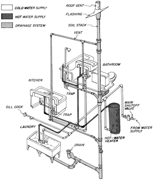
Typical Plumbing System. The plumbing system in a typical home or apartment will look something like the figure shown here. It is composed of three main subsystems:
Supply. Both the cold water (coming directly from the meter) and the hot water (coming from the meter through the hot-water heater) that feed the faucets throughout the house.
Drain. The system that removes the waste water from the home. Since this system is not under pressure, all drain pipes must be sloped toward their eventual outlet.
Vent. This system equalizes the pressure in the drain system so that a quick rush of water does not create a vacuum that will empty the traps and allow gases from the city sewer lines or septic systems to enter the home.
More About Your Plumbing
Analyzing the Plumbing
After locating the pipes and deciding where to tap into the existing lines, you should identify exactly the materials and the sizes of the pipes so you can properly join the existing system to any new plumbing. The sections in this book dealing with the installation of the supply lines and drain systems will assume that the new supply lines will be run in copper and the new drain lines in plastic.
Identifying the Pipes
Hot Water Supply Lines. Both the hot and cold supply lines will usually be the smaller pipes in the system. In very few cases will they be more than 1” in diameter. To be sure of which is which, turn on the hot water faucet in the nearest sink or tub and let it run for a few minutes. The hot water running through the pipes will gradually make one warmer than the other. If neither gets hot, you either have the wrong pipes or the wrong sink, so try another sink before looking for more pipes. If the line is very hot (or if the furnace is not on and the pipe isn’t hot even with a faucet running) it may be a line for hot water to radiators, which you should not cut into.
Cold Water Supply Lines. These will usually look identical to the hot water supply in material and size and will normally run parallel to it.
Drain. This will usually be larger than the supply lines, with a diameter of 1 1/2” to 2” (the main stack will run straight up and down and is 6” to 8” in diameter). Because the drain pipe is not under pressure, it must slope downward from the sink or tub outlet. Use a level to see that it is sloping down. The slope should average about 1/4” per horizontal foot.
Vent. This line will normally tap into a drain line downstream from a trap. It will tend to run upwards because it acts as a gas outlet.
Determining the Materials
Once you know which pipes are which, the next step is to determine what they are made of. There are generally four kinds:
Copper. This comes in rigid and flexible kinds. You can tell one from the other by the number of bends in it. Because flexible copper tubing is normally sold in rolls, it will have small bends and bumps after it has been unrolled and installed. Rigid piping, however, runs straight.
Galvanized Steel Pipe. This is hard and straight pipe. If you scratch it you will see the shine of steel. It often has a dark color from tarnish and a galvanized surface pattern you probably have seen on galvanized garbage cans.
Plastic. A good way to identify plastic is to shave it slightly with a knife. The plastic can be shaved away whereas any other material will just be scratched.
Hubless Cast Iron. If you find this material, you have probably encountered a drain or vent. It will usually be larger than supply pipe and is joined with either leaded joints or special connections.
Darkroom Planning and Shopping
Before buying the materials you need, you should first think through the basic requirements of your darkroom. What is the quality of the incoming water? Is it too hard? Is it full of suspended particles that will end up as white spots on good prints, requiring more time spotting and less time taking pictures? Is there sufficient hot water in the water tank to meet your needs as you foresee them? Is the temperature of the incoming water such that it would be convenient to have a water temperature regulator?
Water Too Hard. Hard water can make chemical mixing more difficult. The problem can be alleviated with a water softener or chemical additives.
Suspended Particles in Water. Often, an accumulation of particles, either in the city pipes leading to your house or in the house plumbing itself, becomes dislodged and comes out of the water faucet, whereupon the particles attach themselves to the finest negative you ever made. One way to prevent this is to use water filters (see Chapter 7 for examples of available equipment).
Temperature Regulation. If you have done much darkroom work, you will have discovered long ago that there are two main problems with temperature regulation, either when mixing chemicals or when washing prints and negatives. The first is caused by your sink having two separate nozzles rather than one, with hot water coming out of one and cold out of the other. The only solution is to make connections to each faucet with a threaded coupling and have the two streams merge through an attachment. However, you will still be left with the second problem that is intrinsic to all systems: keeping the water temperature steady at the temperature you require. To make sure that the water flows evenly at 68°F (20°C), buy a water temperature regulator (see Chapter 7 for available units). The installation of this device ensures that once the temperature is set the water will remain at that temperature plus or minus the manufacturer’s specifications (usually 1/2°F).
Number of Faucets. In addition to the water quality, you should also consider the number and types of outlets available on the sink. The major types are:
Regulated Output. This type is connected through the temperature regulator and used primarily for mixing chemicals, washing prints and negatives, and providing a water bath for development.
An Unregulated but Mixed Hot and Cold Outlet. This unit can be used separately to clean equipment or as a unit to mix chemicals when the other outlet is being used to wash prints.
A Spray Nozzle. Normally found on kitchen sinks. Attached to a long hose, it can be used for such jobs as cleaning of equipment and the sink itself. This nozzle should always be connected to the system with a high-pressure rubber hose and a shut-off valve. Both devices will prevent the hose from breaking while you are away from home.
It is helpful if all outlet faucets swivel and are high enough in their clearance to allow placing tall mixing graduates under them. Normally, there should be a minimum of 15” clearance from the bottom of the sink (or the top of the duckboards, if you use them) to the bottom of the faucet.
Later in this section, we will describe how to build a modular unit containing all of these devices. The unit is designed to be detachable and can move with you from darkroom to darkroom.
Required Materials and Tools
To install a plumbing system, special tools are required, as are certain materials such as pipes and fittings. This section will discuss the most commonly available.
Materials. Household plumbing comes in a wide variety of materials, with the most commonly used being copper, galvanized steel, cast iron, and plastic. Copper is frequently used for supply lines because it satisfies the widest number of municipal codes. Drain lines are often installed in plastic because it is acceptable in a wide variety of locations and is much easier to work with than other materials.
Supply Lines. Copper supply lines come in two major kinds, rigid and flexible. Both have their advantages and disadvantages, and you should make your selection based on your particular needs. Rigid pipe is easier to connect to fittings because its rigidity makes it easier to cut evenly and keep straight. Flexible pipe or tubing is easier to install on long runs, especially those that have occasional obstacles preventing running it in a straight line. Each time the rigid variety turns a corner even slightly, a fitting is required; the flexible kind can be bent as required and less joining is needed.
Copper pipe and tubing comes in three main types based on the thickness of its walls. This thickness determines the amount of pressure the line can safely handle:
Type K—Thick Walled
Type L—Medium Walled
Type M—Thin Walled
Flexible tubing comes in only Type K and Type L. Type L, either in rigid or flexible varieties, is the most commonly used interior pipe and is suitable for the darkroom. In most cases, you will require adaptors to tap into the existing lines in your house. You will normally tap into either a 3/8”, 1/2”, or 3/4” supply line. The size of the line to be tapped can be determined by referring to the earlier section on “Getting to Know Your Plumbing.” The reduction from a larger pipe to the 3/8” or 1/2” pipe you will be using for the new plumbing is done with a reducing T. The kind of T you require is determined by the kind of pipe you are tapping into. The fitting required to tap into a galvanized pipe is different from that required to tap into a copper pipe.
Drain Lines. Plastic pipe is a relative newcomer in the plumbing world, and as a result, its ability to satisfy building codes is not yet uniformly established across the country. You should check with your building department to see if this material will meet the local requirements. The big advantage of plastic, and the reason it is being recommended in this book, is that it is by far the easiest material to work with. Drain pipe made of galvanized steel or cast iron in the large sizes needed can be very heavy when installed in long runs and is therefore very difficult to work with. Plastic pipe, on the other hand, is no more difficult to use than the parts in building a model airplane, and the only tools required are a saw and glue. An additional advantage is that it is not corroded by darkroom chemicals and will last indefinitely without any problems. To install the drain, you will need selected fittings and an adaptor to the existing drain in addition to the pipe itself.
Three main types of plastic pipe are on the market, and their intended uses are somewhat different. The major types are:
PVC—Polyvinyl chloride
CPVC—Chlorinated polyvinyl chloride
ABS—Acrylonitrile butadiene styrene
All three can be used in cold water supply lines, but only CPVC can be used in hot water lines or a drain system. CPVC has been designed to withstand higher temperature without failure.
Typical Darkroom Plumbing
The typical darkroom plumbing requirements are relatively simple. This section shows most of the elements that will be encountered in the existing system and illustrates most of the materials needed for the new plumbing. It is an idealized plan, but by using it as a guide, you should be able to design and specify the materials you need for your own system.
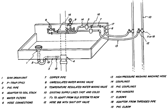
Shopping List for Plumbing Installation.
This general plan for darkroom plumbing illustrates and identifies all of the parts required. The numbers are keyed to the shopping list and to the photographs on the opposite page.
Shopping List
| General Plumbing—Supply | |
| 7. | Copper pipe (rigid) |
| 7. | Copper tubing (flexible) |
| 11. | Saddle T adaptors |
| 11. | T adaptors |
| 17. | 90° elbows |
| 12. | Hose bibs |
| 11. | Reducing Ts Caps |
| 18. | Adaptors to existing pipes |
| 14. | Couplings |
| Faucets if not using filters and temperature regulators | |
| 8. | Long-necked swivel mixing faucet |
| Spray hose attachment | |
| Plumbers putty | |
| Materials needed to build modular plumbing unit with both filtration and temperature regulation (described on pages 76-77) | |
| 5. | Hot line filter |
| 5. | Cold line filter |
| 9. | Temperature regulator |
| 17. | Elbows |
| 11. | Ts |
| 7. | Pipe |
| 9. | Faucet |
| 8. | Long-necked swivel mixing faucet (for unregulated outlet) |
| 13. | Hose |
| 6. | Hose connection |
| Drain | |
| 3. | Plastic drain pipe |
| 4. | Adaptor |
| 19. | Elbows |
| 2. | Trap |
| 1. | Sink strainer/drain |
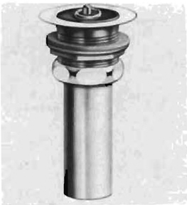
1. Sink strainer/drain
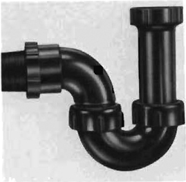
2. Trap
3. Plastic Drain Pipe
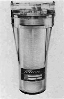
5. Hot and Cold line Filters

6. Hose Connection
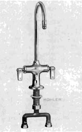
8. Long-Necked Swivel Mixing Faucet
9. Temperature Regulator
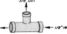
11. Reducing T

12. Hose Bib
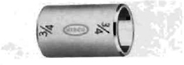
14. Coupling

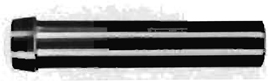
15. Pipe Coupling
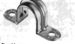
16. Pipe Hanger
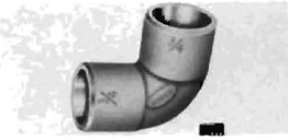
17. Elbow
18. Adaptor
Roughing in the Plumbing
Installation
If you have to do major work to install the system, begin by roughing in the plumbing. Plumbing is installed in new construction after the room has been framed but before the finishing wallboard has been put up. If you are not doing new construction, the plumbing can be hidden behind cabinets, covered by a false wall, or left exposed—although that can become a dust collector.
If you are installing the plumbing in a newly framed (or exposed) wall, you should consider recessing the pipes into either the studs (the 2 × 4s holding up the walls) or the joists (the beams holding up the ceiling). When doing this, there are a few things to remember:
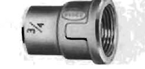
1. All holes in joists should be centered in the vertical direction, and the hole diameters should be no greater than one-quarter of the depth of the joist.
2. A notch can be cut in a joist as long as it does not fall in the middle and is as close to a support as possible. The notch should be no more than one-sixth the depth of the joist and should be reinforced with 2 × 4s nailed under it (if it’s on top of the joist), or reinforced with a steel brace if the notch is on the bottom.
3. When notching studs, a notch cut into the top half should be no deeper than two-thirds of the stud’s depth, but on the bottom no deeper than one-third. The notch should then be reinforced with a reinforcing plate.
Adapting off the Main Supply Lines
The next step after roughing in the plumbing is to make the connection between the new system and existing pipes. This is normally done with adaptors that serve three functions. The first is to provide an outlet from the existing pipe; by inserting a T-fitting into an existing pipe run, you add a new outlet to which your supply lines can be attached. The second function is to marry together pipes of different materials. Special Ts exist to connect copper pipe to copper, galvanized, or plastic supply pipe. The third function is to reduce the main line pipe size to the size pipe you plan on using. If you are connecting 3/8” copper tubing to a 3/8” copper supply line, all you require is a 3/8” T. However, you may require a T that will reduce a 1” supply in galvanized steel to a 3/8” copper pipe connected to your sink. See the description of a saddle T on page 66 before committing yourself to any more complex method of tapping your existing system. Although the illustration shows it being connected to a hose bib so that the sink can be connected through rubber hoses, saddle Ts can be used to connect galvanized pipe to copper and so on. It is a time-saving device that eliminates having to cut and thread steel pipe.
How to Support the Pipes. All pipes should be supported with brackets or hangers at regular intervals. With plastic pipe or long runs of copper, leave the hangers loose enough to allow for expansion and contraction of the pipes.
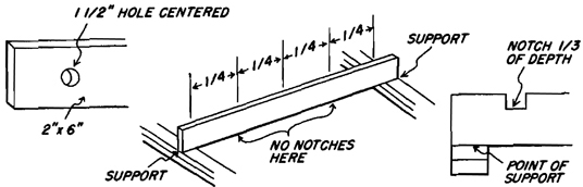
How to Make a Notch
How to Make a Notch. Using a crosscut saw, make two parallel cuts into the stud or joist as far apart as the pipe to be inserted is wide. Cut them to the necessary depth, and then, using a wood chisel, knock out the piece of wood between the cuts.
Cross Pieces
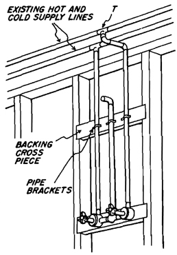
Cross Pieces. In those cases where the plumbing is running parallel to the existing supports, cross pieces can be inserted against which the plumbing can be attached. Be sure the plumbing is recessed sufficiently so that the pipes are hidden, but the fixtures will protrude the correct distance after the finish wallboard or paneling has been installed.
Installing Supply Lines
The advantages of using copper for supply lines are its quality, its ease of installation, and its ability to meet most codes.
Measuring Pipe and Tubing
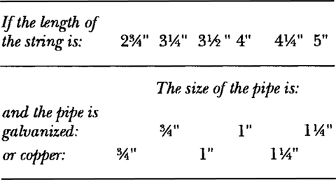
How to Determine the Diameter Needed. Most of the plumbing you install for the darkroom will be 3/8” or 1/2” in diameter on the supply side and 114” or 2” on the drain side. It is important to determine the size of the existing system into which you will tap to know what size adaptors to buy. The outside diameter is not a completely accurate guide, because the diameter in which pipe is sold is determined by the size of the hole running through it. The pipe you normally encounter in the wall has all its holes covered (otherwise it leaks), so you have to make a determination based on the kind of material and the outside circumference. The table below will give a good indication of the size of the existing pipe. Run a string around the pipe and mark where it crosses. The distance between the two points is the circumference of the pipe.
Measuring the Length of Pipe Needed
When measuring the length of pipe required, take into account the fittings into which the pipe is eventually going to be inserted. The easiest way to do this is first to measure the distance from the end of the fitting to where the pipe will be stopped when inserted. Now place the fittings exactly where they will be installed in the system and measure the distance from one face of the fitting (the end) to the other. Add this measurement to the distance determined above (add it twice, for there are usually two fittings, one at each end) for the total length of pipe required.
Measuring Pipe
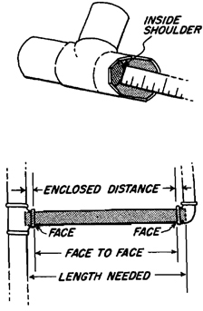
If you plan to work with threaded pipe, you can use the following table to indicate how far you can expect the threaded pipe to go into the fitting. Again, remember that there will be two fittings, so the distance that the pipe goes into the fitting should be doubled before adding it to the face-to-face measurement.
Distance Threaded Pipe Extends into a Fitting
| Size of pipe | Distance into fitting |
| 1/2” | 1/2” |
| 3/4” | 1/2” |
| 1” | 9/16” |
| 1-1/4” | 5/8” |
| 1-1/2” | 5/8” |
| 2” | 1-1/16” |
Working with Copper Pipe
Cutting. There are two ways to cut copper pipe. The first is to use a hacksaw to make the cut and a file to smooth off the burrs. An easier method is to use a tube-cutter, ensuring a square and smooth cut in the pipe or tubing.
Connecting Copper Pipe or Tube to Its Fittings. There are four types of connections that can be made with copper tubing or pipe: soldered (used for either rigid or flexible pipe); threaded (rigid only); flared (flexible only); and compression (flexible only). Compression fittings are the easiest to use and require no tools other than a pair of wrenches.
Using a Mitre Box
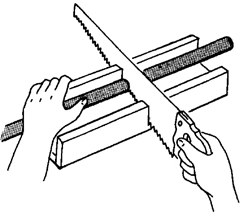
When cutting with a hacksaw, it helps to use a mitre box to ensure a square cut in the pipe.
Filing Off Burrs
After cutting the pipe, be sure to file off the burrs left by the saw blade.

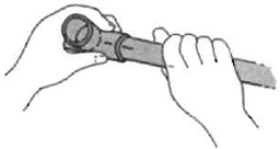
The tube-cutter works by revolving it around the tube and gradually tightening the screw handle so the rotary blade cuts deeper and deeper into the wall of the pipe. If you turn the handle too fast, it can flatten the pipe and make a connection difficult when it comes time to connect it to a fitting.
Using a Reamer
All you have to do after cutting with the tube-cutter is to rotate the reamer in the opening until the sharp edge is removed and a smooth end is made.
Cleaning End of Pipe
All surfaces should be cleaned and free of grease or dirt to ensure a strong joint. Use steel wool, emery cloth, or a wire brush.
Applying Flux
Flux keeps the tube from oxidizing when you apply the torch, making the solder stick better to the tube and fitting. Coat both the outside of the pipe and the inside of the fitting.
Applying Solder
The hottest part of the torch flame is where the blue flame meets at a point. Apply this portion of the flame to the fitting (not the pipe). Keep touching the solder to the pipe and fitting where they come together. When the solder begins to melt, fill the joint evenly (the solder will automatically be pulled into the joint by capillary action) until it is full. Do not move the fitting or the pipe until the solder has hardened; otherwise, you may eventually have leaks.
Wiping Joint
Before it hardens, remove excess solder with a small brush or wiping cloth.
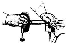
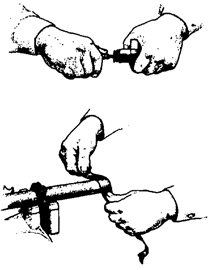
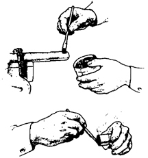
Bending Pipe
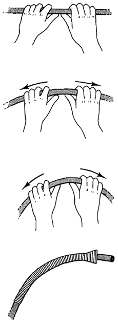
Bending. Copper pipe should not be bent, because it is too rigid. Bending copper tube can be a problem, because if the tube is bent too fast or too sharply the walls can collapse. This is fine when you’re trying to impress someone by bending a Coors can in one hand, but the plumbing inspector frowns on it in your plumbing system. There are two ways to prevent this. The first is simple: bend it slowly from the center of the bend outward while supporting the side toward which it’s being bent with the thumbs of each hand. Gradually work your hands out as you continue the bending action. Make a few passes along the pipe to complete the bend rather than doing it all at once.
The second and simpler method is to use a bending spring that distributes the force of the bending evenly along the tube and supports the tube so the walls do not collapse.
Installing the Drain
If your building code permits the use of PVC plastic pipe for drains, you are in good shape. To install this material you basically need only a saw and some glue. Additional tools may be required where you tie into the existing system. The installation of a drain pipe encompasses three steps:
- Installing the drain outlet in the sink.
- Connecting a trap to the sink.
- Running the drain pipe and connecting it to the existing DWV (drain-waste-vent) system.
Drain Assembly
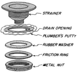
Drain Assembly. Buy a sink outlet unit that matches the drain pipe you intend to install (usually I 1/2”). Drill a hole in the bottom of the sink at its lowest point, and install the unit following the instructions that came with it. Or use the illustration above as a guide.
Fitting Drain in a Wooden Sink
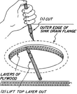
Fitting Drain in a Wooden Sink. If your sink drain is being installed in a wooden sink, you should first drill or saw the hole to hold the unit. The next step is to recess the flange that keeps the drain from falling through the hole. If it is not recessed, water will build up in the sink to the top of the flange. The best way to do this is to insert the unit in the drain, draw a circle around the outer part of the flange, and remove the unit. At this point, carefully cut the circle out to the depth of the flange. If the sink bottom is made of plywood, one of the levels of laminate will be approximately the same height as the flange. After the circle is cut, use the knife to separate the top layer of plywood and remove it.
Assembling the Trap
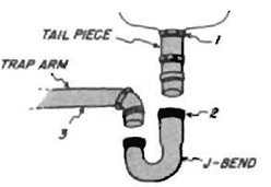
Assembling the Trap. Install a P-trap consisting of three parts (usually available as a unit): (1) a tail piece coming from the sink drain; (2) a J-bend; and (3) a trap arm.
Installing the Run to Existing Drain Pipe
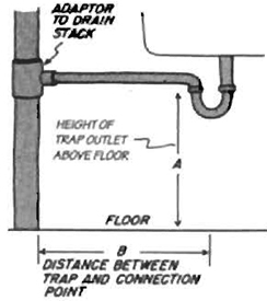
Installing the Run to Existing Drain Pipe. The P-trap should now be connected to the existing drain system. All drain pipe must slope toward its outlet at the rate of 1/4” per linear foot. To determine this, measure the height of the bottom of the trap outlet you have installed and the horizontal distance between it and the pipe to which you will connect the drain. Multiply the 1/4” drop times the number of horizontal feet and that will tell you how far to drop the pipe over the entire run. Subtract that number from the distance between the bottom of the trap outlet and the floor; this determines how far up the existing drain you should make your connection. Most building codes require, and common sense dictates, that no part of the drain pipe can be below the top part of the U-bend in the trap. This is to prevent the pipe from acting as a siphon and emptying the trap, which would allow sewer gas to enter the darkroom. This requirement, when related to the need for the pipe to drop 114” for each foot that it runs, means that a sink outlet can be no farther than 4 114’ from the stack if the drain pipe you are using is I 1/4” in diameter, or 5’ if the pipe is 3”. This measurement can influence the location of the darkroom, as well as the sink and the sink’s drain. Everything should be done to ensure that the outlet meets these requirements, because installing a new DWV stack can be very expensive.
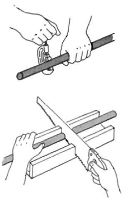
Cutting the Drain Pipe. Working with plastic pipe is easy. First measure the pipe run needed, as demonstrated earlier in this section. Then, make the necessary cuts, using either a hacksaw or special plastic pipe cutter similar to the one illustrated. When cutting with a hacksaw, use a mitre box to ensure straight, square cuts.
Removing Burrs
After cutting, all burrs should be removed with a burring tool, and the end of the pipe cleaned of all dirt and grease.
Aligning the Joint
Working with the Pipe. Insert the pipe into the fitting to make sure it fits. Align the fitting on the pipe in the direction it will actually point. Mark the location with a pencil.
Applying Solvent Cement
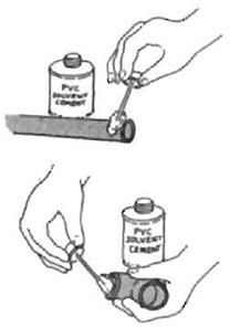
Remove the fitting and apply PVC solvent cement to the outside of the pipe up to the point where it will extend out of the fitting. Also coat the outside of the fittings. Quickly place the fitting over the pipe and align the pencil marks. Because of the speed with which the cement dries, this should be done within one minute.
Adapting to the Stack
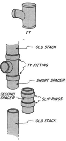
Connecting to the DWV Stack. Connecting the sink to the existing stack requires that the stack be cut and a TY fitting inserted. Hold the TY against the stack with the outlet centered where you have marked the center of the drain to be. Mark the stack to indicate where the top and bottom of the TY are to be.
If the Stack is Hubless Cast Iron. If the stack is hubless cast iron, the stack should be cut with a pipe cutter (which can usually be rented). The TY is then inserted in the line and connected with rubber sleeves and clamps (available at your plumbing supply store).
If the Stack is Copper or Plastic. If Adapting to the Stack the stack is copper or plastic, the lower cut into the existing stack should be about 8” below the center line of the TY inlet. This allows room for a spacer to be inserted in the line to adapt the TY to the existing stack. First, make the connection to the top cut with either solder or cement (for plastic), and then cement or solder a short spacer into the bottom of the inserted TY. Then cut a spacer to fill the remaining gap and seal it to the spacer above and the existing drain below with slip fittings at both ends. These fittings should also be soldered or cemented in place.
The Easy Way Out and Unique Solutions _
A Unique Solution
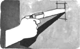
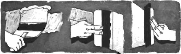
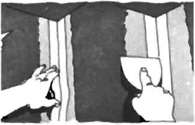
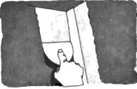
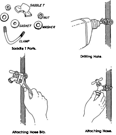
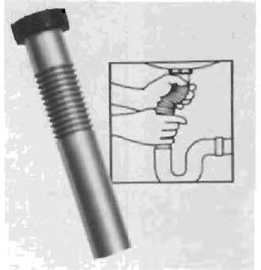
If you are lucky, your entire plumbing connection can be made between the sink assembly and the existing water supply in a matter of minutes. All you need is a “saddle T.” You can bolt this device onto the existing pipe and then drill through to tap the water line (the water should be turned off and the drill grounded). Screw a hose bib into the saddle-T fitting and connect the sink to the water supply with the high-pressure water hose used for washing machines. Either tap the drain into the existing drain, or run a rubber hose from the sink drain into the existing sink, bath, or shower to provide drainage.
Saddle-T Assembly
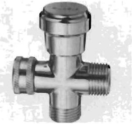
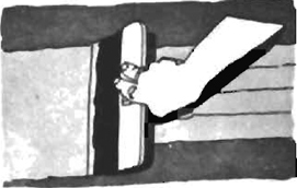
Shower Diverter. If you build your darkroom in a bathroom, you can purchase a shower diverter that allows you to use the shower and, at the same time, provide a convenient connection for a hose that can run to the print washer or to the sink. The diverter is easy to install; remove the shower head, screw on the diverter, replace the shower head, and connect the darkroom hose. These diverters by Alsons are available in most hardware stores.
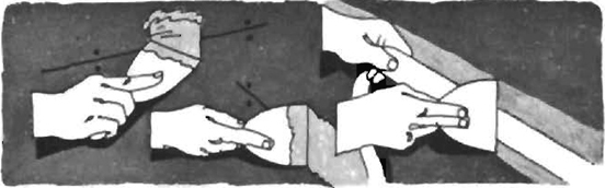
Making Flared Joints
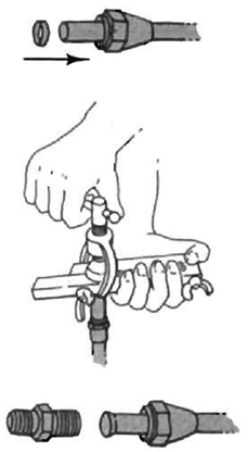
Making Flared Joints. Fit the threaded portion of the fitting onto the tube before beginning the flaring operation. Then slide on the metal gasket.
Insert the tube into the flaring block so its end protrudes just slightly. Screw the tapered head of the flaring tool into the tube, making it flare into a funnel shape.
Screw the male-threaded fitting into the fitting that was first put on the tube. Tighten it down with reasonable pressure.
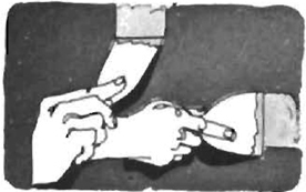
Making Compression Joints
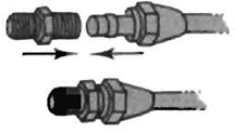
Making Compression Joints. Slip the female fitting over the tube, followed by the metal gasket.
Insert the male fitting and, using wrenches, tighten the joint.
Draining Uphill
You may find that your darkroom does not have a drain to connect with that is lower than the sink outlet you plan to install. To get the waste water out of the sink and up to the drain, you will have to install a pumping system. First, determine the rate of flow of your pump. Your plumbing store or plumber can help you with this. Usually, installation instructions will be included with the pump. If they are not, you can follow the basic instructions covered in the section ‘Installing the Drain” above.
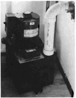
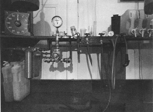
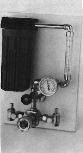
Pumping water uphill to an existing drain line was the least expensive solution when Rick Ashley installed his darkroom in the basement of an older Marblehead, Mass. home. The unit consists of a holding tank with float valve, a pump, and a check valve. The water from the sink flows into the tank, and its level is measured by the float, which automatically turns the pump on and off as needed. The check valve prevents water from flowing backward in the system.
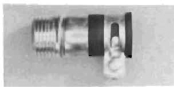
Pfefer Phittings.
The Pfefer Company distributes a complete line of plumbing connecters for darkroom use. The ones shown below are typical of the wide range available.
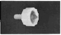
Swivel Hose Connecter. Has female garden hose swivel. Models are available to connect to 1/4”, 3/8”, and 1/2” ID (inner diameter) tubing.
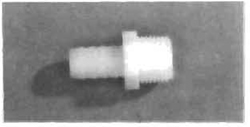
Barbed Hose Connecter. Designed for use when connecting a hose to any tank or tray. Models are available to connect to 1/4”, 3/8”, and 1/2” ID hose or tubing.
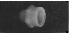
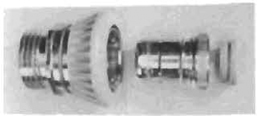
Adaptor. Models are available to connect garden hose to 112” or 3/4” male pipe threads.
Clamp-on Hose Adaptor. Connects garden hose to threadless faucets. Similar model has snap fitting to connect to snap nipple.
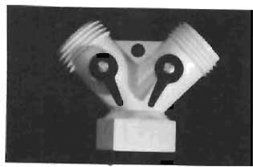
Y-Adaptor. Designed to give two outlets from one water source, each with separate shut-off valve. All fittings connect with garden-hose threads.
Thermometer Well. Can be inserted in line to hold thermometer in water flow. Allows constant monitoring of the incoming water temperature.
Snap Coupler. With all hoses and fittings connected with snap couplers, lines can be changed around quickly without having to unscrew threaded fittings. Makes connections quick and easy.
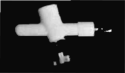
Drain Alignment Mistakes. Installing a drain can be like digging a tunnel from two sides of a mountain: if they don’t meet in the middle, they don’t do much good. If you find that your drain and sink don’t meet where you had planned, this flexible connecter by Webstone can be used to cover this mistake.
A Modular Plumbing System
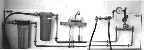
The plumbing system shown here is mounted on a large panel over the darkroom sink. It is connected to the house plumbing supply with high-pressure rubber washing-machine hoses. This modular design allows the sink and plumbing system to be moved into a new darkroom. You can assemble the unit at a workbench, which is usually easier than assembling a unit permanently on the wall.
The Components
This modular unit consists of a temperature-regulating valve by Mey-nall, two in-line water filters by Arkay, and an unregulated mixing valve.
Laying Out the Units. Cut a plywood panel (5/8” or 3/4”) the length of your sink and at least 2’ high. Assemble the basic components on the boards in the rough positions they will occupy.
- Filters have an input and an output side, so align them as indicated in the directions that come with them.
- Determine the correct mount for the unregulated outlet. Since most faucets are designed to be connected from either the rear of the unit or from the bottom, your mount may vary somewhat from the one illustrated. If possible, use the type that is plumbed from the bottom and cut a 2”-thick piece of wood large enough to hold it. This can later be mounted to the plywood panel with long bolts.
- Mount the regulator valve on the back panel.
- Using a black pencil, draw lines connecting the cold water lines from the outlet side of the filter to both the regulated and unregulated valves. Make sure that they are fed on the correct side. Both units will be marked as to which side is hot and which is cold.
- Using a red pencil, trace the hot water supply lines from the outlet on the hot water filter to the regulated and unregulated valves.
Assembling the Unit. The unit should be assembled using 1/2” copper pipe with soldered joints.
- Determine the exact fittings required for the assembly. Each right-angle turn will require an elbow; each fitting will require a matching fitting that fits into or on it; each connection from the main line to a branching line will require a T.
- With this list of components in hand, visit your local plumbing supply store. A plumbing supply store will probably be more useful than a hardware store: the line of parts is usually larger, and the people are more knowledgeable about your needs.
- If you are unsure about fittings for certain parts, take the parts with you so that the salesperson can determine the right fittings.
- Begin the assembly by laying the fittings on the board in the places indicated by the sketch you drew earlier while doing the layout.
- Measure the lengths of pipe needed to connect these fittings. Be sure to include the portion of the pipe that will fit into the fitting.
- Cut the lengths of pipe needed, and assemble the entire unit to be sure that everything lines up and fits correctly.
- Remove the copper pipe and fitting and solder all of the joints. Where fittings are to be set at various angles, be sure to mark the proper alignment (scratch the pipe and fitting with a knife) so that they can be reassembled in the correct alignment.
- Reassemble the soldered units on the panel and connect the fittings to the filters, and the faucets with the threaded fittings. Be sure that all threaded fittings are tightened securely and sealed with pipe-joint cement.
- Connect the unit to its supply by attaching the high-pressure washing machine hoses (regular hose will break and flood your darkroom). They can be connected to the existing supply lines with a saddle-T adaptor.
- Turn on the water and check for leaks.
Introduction to Electricity
If plumbing is intimidating to the average person, electrical wiring can be downright terrifying. Very few photographers have drowned while installing plumbing, but you can bet there have been a few shocks for those installing their own wiring. Electricity can be fatal, and this is especially true in a darkroom where the presence of moisture contributes to electrical conductivity. Wiring should be attempted only by knowledgeable people, and even then it should be inspected by a licensed electrician to be sure there are no hidden flaws. Wiring over sinks, faulty grounding, or cables in moisture-laden places all contribute to serious problems. If you are not experienced enough to take on this job yourself and yet don’t want to spend a great deal of money, find an electrician who will do the heavy wiring (service entrance wiring, fuse panels, etc.) but will allow you to do the installation of cable runs, light switches, power outlets, and so forth, and inspect the job upon completion. This method will save money but also guarantee that the job has been done correctly.
In this section it is assumed that you are confronted with one of two common situations.
Utilizing an Existing Outlet. If your darkroom has walls that have been finished and you don’t want to get involved in any heavy construction work, you can build an electrical control panel that plugs into an existing outlet. The only requirement is that the circuit into which you are plugging can carry the expected load. To make these calculations use the information in the next section, “Electricity in the Darkroom.” This method has several advantages. Primarily, it requires no damage to the existing room, so it can be reconverted to its original purpose without any extensive work. It’s easier and less expensive than redoing the entire room wiring and is equally functional and effective. The unit can be constructed on a kitchen table and, when you move, it can go with you and be plugged into the next darkroom. Instructions on how to build this unit follow later in this section.
Rewiring from the Service Entrance. When you want a permanent installation, you can wire the darkroom circuits from the service entrance (fuse panel) to the darkroom outlets and switches. Before beginning this installation, you should check with your local building department and become familiar with the relevant codes. Failure to follow the laws of your community could make your insurance policy invalid should injury or fire occur as a result of a faulty installation.
How Your Electrical Circuits Work
The electric current for your residence enters from the street through heavy-duty cables. The first connection after they enter the house is to a fuse panel. This panel (called a service entrance) performs two functions. The first function is to take the incoming current and distribute it to a number of smaller circuits. This allows the house wiring and equipment to be of a smaller size than it would be if all of the house current went through one large circuit. In this respect it’s like an eight-lane expressway coming into the panel with a large number of one-lane exits leaving to various parts of the house. The second function of the fuse panel is to prevent the wiring from catching fire or melting should it become overloaded. This is accomplished with fuses or circuit breakers. When current flows through a wire it generates heat. If there were no fuses, and you drew more current than the system was rated for, the wires would become hotter and hotter until they or the surrounding material caught fire. The fuses are made to break or interrupt the circuit if current flow ever exceeds the capacity of the circuit. Never try to increase the capacity of a circuit by inserting pennies in the fuse holder or by increasing the rating of the fuse you install. Either of these solutions creates fire and safety hazards.
When wiring your darkroom it is important to know what your circuits and fuses are rated at in amps (the higher the rating the more current the line can carry) and what outlets are currently on which circuits. You also need to know what the darkroom load on your circuits is expected to be, as well as the load on other outlets that may already be wired into the circuit you plan to use. If you calculate that your darkroom will require 12 amps and your circuits are rated to carry 15 amps, you can wire off an existing circuit— provided other outlets already wired into the circuit are using no more than 3 amps. If they are using more, or if your circuits are rated at less than you need, you will either have to install an entirely new circuit or split your darkroom load between two existing circuits.
How to Tell What Outlets are on What Circuits
If you plan to run the wiring off of an existing circuit, you should first figure out what outlets and current demands are already on that circuit. These other outlets and their loads must be taken into consideration when determining if the circuit can handle the load your darkroom will add to it.
The wall outlets and the lighting fixtures in a home or apartment are generally installed and wired before the final wall panels are installed. This means that the initial wiring is located for reasons of convenience and economics. All outlets in all rooms are usually not on the same circuit. So be sure to check the entire house when trying to decide what outlets are on which circuits.
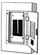
- Draw the fuse panel (or circuit breakers) showing their arrangement in the box.
- Turn off the master power switch or pull the master fuse. This will kill all of the electricity in the house and make it safe to pull one of the circuit fuses. If your house is on circuit breakers, they are safe to switch without turning off the master switch.
- Remove one fuse or turn one circuit breaker off.
- Turn the main power switch back on. This will restore all electrical power, with the exception of the circuit from which you removed the fuse or turned off the circuit breaker.
- Using a voltage tester (see ‘Tools and Materials for Electrical Work” below), or by plugging in a small lamp, check all of the outlets in the house to see which ones don’t work. These are all on the circuit from which you removed the fuse. Also check all light switches to see which lights are on the circuit; don’t forget to check such heavy appliances as the refrigerator, washing machine, and so on. Any appliance outlet or switch on each circuit should be noted on your drawing.
- Turn the master switch off; turn the circuit breaker back on or replace the fuse. Take out another fuse and repeat the same process. If working with a fuse panel, always turn off the main power before removing or installing a fuse just to be safe.
When you have completed this chart, you should know what is already on the circuit to which you want to make your connection. If any heavy appliances such as washing machines or space heaters are on the same circuit, you should change your plans because their load is guaranteed to be too high. It may also be against your building codes to connect into those circuits. In any event, whatever is already on the circuit should be used in making the power calculations in the next section.
Electricity in the Darkroom
How to Calculate Power Requirements
When you are working in your darkroom, you are drawing current from the house electrical system. Because house wiring is designed to carry a specific load and no more, it is important to be sure you will be within those limits. If you are not, you will be cursed with blown fuses or tripped circuit breakers. The easiest solution is to prevent problems initially. This section will help you calculate the expected load so that corrective action can be taken before you have problems.
Computing the energy requirements in your darkroom, and then comparing those with what the wiring will allow, is really very easy. There are three units of measurement involved:
Volt. A unit of measurement of the electrical pressure in a circuit. It is similar in this respect to measuring air pressure in pounds.
Amp. A unit of measurement for flow in the circuit. Similar to measuring water flow in gallons per minute.
Watt. A unit of measurement representing power consumption.
Most of the appliances you deal with consume a fixed amount of power when they are operating. This amount is almost always expressed in watts. Unfortunately, your house circuits are rated in amps. To find out what power you need (in amps), you must add all of the devices expected to be on the circuit you plan to use so you know the total number of watts. Then convert this figure to amps to see if your circuit can accommodate the load. To do this, you can use the following table:
Calculating Power Requirements
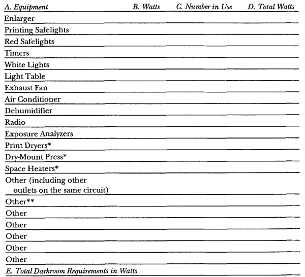
* These items are unusually large users of power and should be placed on separate circuits if at all possible, or not used at the same time as the darkroom if they have to be on the same circuit.
** Under “Other” you should also refer to the chart showing what other outlets are on this same circuit and add those in this space.
How to Use This Table
A. Column A lists the most commonly used darkroom equipment. It is essentially a checklist of what you have now or might have in the future. Under “Other,” list anything additional you plan on having.
B. In this space list the power requirements for the equipment in watts. If you already have the equipment, you can usually find its rating in watts on a plate that also lists additional information, such as manufacturer’s name, serial number, and so forth. If you do not have the equipment, use the following table of normal (or average) ratings:
| Safelights | 15-40 |
| Enlargers | 75 |
| White lights | 40-100 |
| Timers | 25 |
| Exhaust fans | 75 |
| Air conditioner | 800-3000 |
| Dehumidifier | 550 |
| Radio (solid state) | 25 |
| White light (fluorescent) | 100 |
C. In this column, list the number of similar pieces of equipment you will have. For instance, you will probably have more than one incandescent light bulb in the room.
D. Multiply the number in Column B times the number of units in Column C and enter the figure here, in Column D.
E. Add all of the numbers in Column D to give you a grand total for the darkroom. You now know what your energy requirements are; now convert the watts to amps to see if your circuit will carry the load.
Converting from Watts to Amps
To convert from watts to amps, use the formula:
![]()
If you live in the United States, divide the results from Row E of the previous table by 115 (the standard American voltage) and you will know how many amps are required. In England or Europe, you would divide by 220 for the same result.
You can also use the following table:
| If you are using wattage between |
and you live in the U.S. (115 volts) your circuit must be capable of carrying |
Europe 220 volts |
| 0-100 | 0.9 amps | 0.5 |
| 100-200 | 1.8 amps | 0.9 |
| 200-300 | 2.6 amps | 1.4 |
| 300-400 | 3.5 amps | 1.8 |
| 400-500 | 4.4 amps | 2.3 |
| 500-600 | 5.2 amps | 2.7 |
| 600-700 | 6.1 amps | 3.2 |
| 700-800 | 7.0 amps | 3.6 |
| 800-900 | 8.0 amps | 4.1 |
| 900-1000 | 9.0 amps | 4.6 |
| 1000-1100 | 10.0 amps | 5.0 |
| 1100-1200 | 10.5 amps | 5.5 |
| 1200-1300 | 11.5 amps | 5.9 |
| 1300-1400 | 12.5 amps | 6.4 |
Do You have Enough Amps in Your Circuit?
In most modern American homes, the circuits are wired up to handle a load of 15 amps. Older homes vary, and you should check carefully to determine what their rated capacity is. If your answer to the previous calculation is less than the rated capacity of your house, you will have no problem using the circuit you planned. If your answer was more, there are a few solutions:
Typical Darkroom Circuits
1. Eliminate some of the equipment.
2. Put some of the equipment on a separate circuit. Use your drawing to determine the closest convenient one that is truly a separate circuit and notjust a different outlet on the same circuit.
3. Do not use all of the equipment at the same time. You can easily change your work habits so that you are not drying prints when the enlarger is on, or vice versa.
4. Add a new circuit coming from the fuse panel rated at the capacity you need.
Solutions NOT to use:
1. NEVER put pennies in fuse boxes.
2. NEVER put higher-rated fuses in the box. You cannot do this safely without changing the wiring.
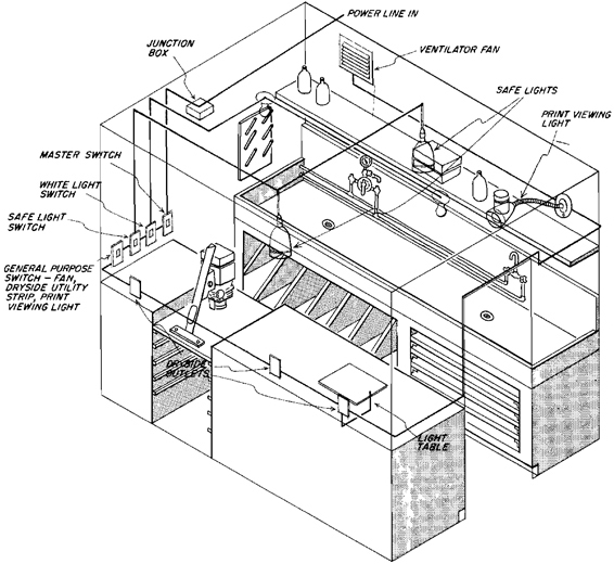
Placement of Electrical Circuits in the Darkroom. This illustration shows the typical arrangement of required electrical fixtures, outlets, and switches. The drawing shows three separate circuits for white lights, safelights, and outlets. There is also a master switch controlling all power to the darkroom.
- All switches should be located near the enlarger as a matter of convenience.
- All safelights should be located at least 4’ from where light-sensitive materials will be used, that is, the enlarger easel and processing trays.
- The switch controlling the white-light circuit should be separated from the other switches to prevent accidentally turning the lights on when materials are exposed.
- All electrical outlets should be mounted at least 3’ above the floor to eliminate the hazard of walking on wires plugged into them.
Tools and Materials for Electrical Work
All of the materials needed to wire darkroom circuits are available at local hardware stores. Make a list of all the parts you need before you go, because once you are working on electricity in the house, it will be difficult to safely turn it back on until the job is completed.
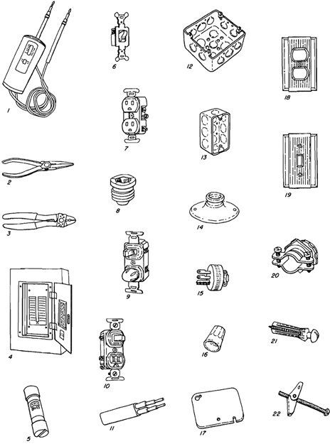
Tools
Voltage Tester (1). This device is used to determine if a circuit is live. It will light up if there is voltage in the circuit. It is also used to determine what outlets are on which circuits and to make sure that the circuit is not live before working on it.
Pliers (2). These are used to twist together the ground wires, which are usually too heavy to twist by hand.
Wire Strippers (3). Wire can be stripped with a knife but wire strippers are better. The surface of the wire should not be damaged when stripping; such damage could cause a short circuit.
Equipment
Fuse Panel (4). A modern fuse panel with circuit breakers will be located near the source of the incoming electrical lines.
Fuses (5 and 8). Fuses in older panels will look like the illustrations shown here. One screws into place, and the other snaps into holding clips.
Wall Switch (6). Used to control power to circuits and outlets in the darkroom.
Outlets (7). Used to plug in darkroom equipment. Always buy the type that accepts grounded plugs.
Switch with Pilot Light (9). This switch can be used to control all outlets in the darkroom. The light will indicate if the circuits are on or off.
Switch Outlet (10). You can use these outlets in place of regular outlets if you want to be able to turn individual outlets on or off at the outlet itself.
Cable (11). Most wiring today is done with what is called NM (nonmetallic) cable, which replaces armor cable found in older homes. Be sure to buy it with two wires and ground. Also be sure to buy it with large enough wires to carry your load. In most cases, you can use a #12 wire, but after determining the load you expect to put on the darkroom, check your building code to see if this is sufficient.
junction Boxes (12). These are used as a point to connect two or more cables: they are the only place where cables should be spliced or connected to each other.
Switch Boxes (13). These are similar to junction boxes, but somewhat smaller in size, and are used wherever a switch or outlet is to be connected. They are mounted to a stud so that the front of the box will be flush with the eventual wall surface. The switch or outlet is wired into them and then covered with a face plate.
Light Fixture (14). These are inexpensive ceramic fixtures that attach to switch boxes recessed in the wall. They are ideal to use to screw in bulbs or safelights and are a great deal cheaper than more elaborate fixtures.
Grounded Plug (15). All cords in the darkroom should have grounded plugs similar to the one shown. This ensures that the equipment ground will connect with the grounded circuits in the house wiring.
Wire Nuts (16). When connecting cable, the wires are stripped about 3/8” back from the end and then two or more can be held together by one of these “nuts.” The nuts eliminate the need for soldering and are available in different sizes, depending on size or number of wires to be connected.
Junction Box Cover (17). Once the wires have been installed in a junction box (12), a protecting cover should be screwed in place to close the box.
Wall Plates (18 and 19). After switches or outlets are installed, they are finished off by installing a plate over the box in which they are mounted.
Connecter (20). These are used to attach the cable when it enters the junction box or switch. They should always be used, because they protect the cable from stress and abrasion.
Fasteners (21 and 22). When installing equipment against wallboard, these fasteners can be used to mount in places where there is no backing into which screws can be fastened.
Wiring the Circuits
How to Wire the Circuits
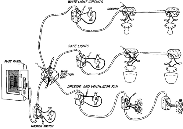
How to Wire the Circuits. This drawing shows a typical darkroom circuit with a master switch controlling separate circuits for white lights, safelights, and a general circuit for the dry side. Wiring can be run directly from the fuse box, or it can begin from an available junction box—provided the load is within the limits of the circuit being tapped.
Things to Remember
1. Before working on any circuit, be sure you pull the fuse or interrupt the circuit breaker in the service panel. To be safe, shut down the master power switch and ALSO remove the fuse for the circuit you are working on. Use a voltage tester or plug in a lamp to be sure the circuit is not hot. Do not be careless, since you can be fatally injured by failing to follow this step.
2. Always use grounded cable for all circuits. Grounded cable consists of a white wire, a black wire, and a bare copper wire. The bare copper wire is the ground and should always be twisted together with all other ground wires in the same box and then fastened to the box itself. This will ensure that all circuits and boxes are at the same electrical potential as the earth, and if there is a short, the current will go through the ground wire and not you.
3. Always buy outlets that will accept the 3-pronged grounded plugs. If you don’t, then the equipment itself will not be grounded, even though the circuit is, and you will be in danger and have wasted your time grounding the circuits.
4. The white wire in the cable is the neutral wire (this does not mean you can touch it with the power on) and should always be connected to the silver terminal in outlets. When wiring a switch, the white wire is connected straight through to the other white wires and should never be connected to the switch terminals.
5. The black wire is the hot wire and should always be connected to the brass terminals on switches and outlets. When wiring switches, it is the black wire that is connected to the switch.
6. Always use connectors when running cable into a junction or switch box. These connectors protect the cable from being cut by the rough edges of the box and also from being pulled loose.
DANGER! No wiring should be attempted without having it inspected. Failure to do so can be extremely dangerous and in violation of local laws. The material in this section is for descriptive purposes so you can discuss it with a licensed expert. Do not use these drawings and captions as a guide to wiring.
Wiring in a Junction Box
Wiring In a Junction Box. Run the cable into the junction box leaving 6” of cable past the point where the connector will fasten it to the box. Mark the point where the cable is flush with the inside of the connector.
Remove the outer sheath of the cable at the place marked, being sure not to cut into the insulation of the wires inside. A small knife blade can be used to cut outward through the plastic sheath, ensuring that the wires are not cut.
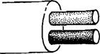
Attach the connector to the box, using the nut that comes with it.
Run the cable through the connector so that the end of the sheath comes flush with the inside of the connector.
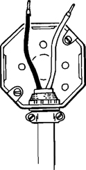
Carefully remove the insulation from the last 3/8” or so of the wires.
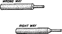
Hold the exposed wires together and screw the correct-sized wire nut over the ends to hold them together. If too much insulation has been removed, you will see bare wire when the nut is screwed tightly into place. This should be corrected by removing the wire nut and trimming the end off the wire, so that when it is rescrewed into place no bare wire is exposed.
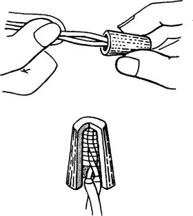
Twist the ground wires together tightly. In some junction boxes, the ground wire can be attached with a clip to the side of the box.
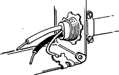
The completed wiring in the junction box will look like the one in this illustration, with all of the wires tightly connected by wire nuts. Now, carefully fold up the wires and place them in the junction box and screw the cover into place.
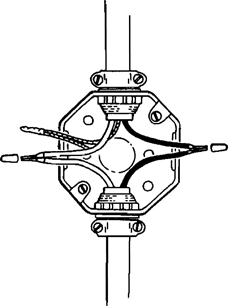
Connecting Wires to Switches
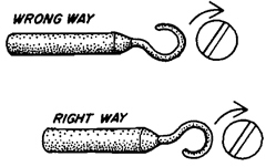
Connecting Wires to Switches. Those wires that are to be connected to terminal screws on switches or outlets should be twisted together and bent to fit around the screw head on the switch. They should be installed with the wires pointed in the same direction that the screw will be turned to tighten it, that is, clockwise, so that they will not be pushed out by the screw as it is tightened.
Wiring on the Surface
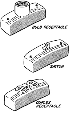
Wiring on the Surface If you are converting a room that is already panelled, or made of some material such as concrete block that you cannot run wires through, you can choose to run all of the darkroom wiring on the surface rather than behind the wall. To do this, you will need special fixtures made especially for this purpose. Junction boxes can be surface mounted, then the three items illustrated replace the usual bulb receptacles, outlets, and switches. The cable can be stapled into place or hidden inside conduit.
Modular Control Panel
Building a Master Electric Control Unit
When installing a darkroom in an apartment, or in a finished room that may eventually be converted back to its original use, it is wise to do as little interior conversion as possible. This section shows you how to build an electric control panel that will put all of the electrical controls at your fingertips. All that’s required, once it’s built, is to plug it in. It has the following advantages over rewiring the room:
1. It can be built in your shop, on your kitchen table, or by a friend, and then installed in the room just by plugging it in.
2. It can be taken with you if you move. All you have to do is plug it in the next apartment or house.
3. It has two outlets for safelights, each on separate switches.
4. It can be adapted to allow the unit to be plugged into two separate outlets (provided they are on separate circuits; see “How Your Electrical Circuits Work” earlier in this chapter), thereby dividing the darkroom load so it does not exceed the limits of a single circuit.
5. It can be used to feed a remote power strip installed elsewhere in the room as a power supply. If the control unit is mounted on the dry side near the enlarger, the remote strip would be near the wet side (never close enough to the sink to get wet), or vice versa.
This unit is based on the actual switches listed. If you use different switches, the wiring will be different. Wiring diagrams usually accompany electrical parts and can be used as a guide.
Building the Case
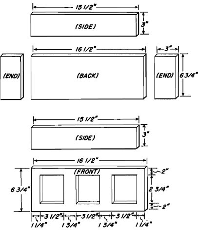
Building the Case. The first step in assembling the control panel is to build a case to hold the switches and outlets. This case can be cut, to the dimensions indicated, from 1/2” plywood. The back sides and ends are glued, then nailed together. The front panel is attached to the case with wood screws, so that it can be removed if necessary to repair wiring.
DANGER! No wiring should be attempted without having it inspected. Failure to do so can be extremely dangerous and in violation of local laws. The material in this section is for descriptive purposes so you can discuss it with a licensed expert. Do not use these drawings and captions as a guide to wiring.
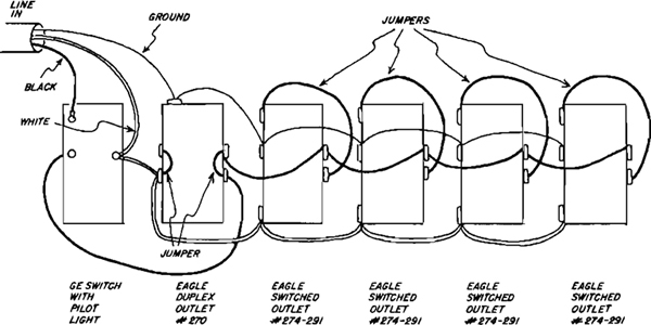
Wiring Diagram This wiring diagram is for a series of switches and outlets identical to the ones listed. As all switches vary in their design, switches other than those indicated will require slightly different wiring.
This view is from the back of the switches. The best approach is to mount the switches to the front panel of the case before attempting to wire them. This will keep them from shifting about and lessens the chance of an inadvertent short circuit.
Never work on the panel with power supplied to the circuits. Also, have the wiring checked by a licensed electrician prior to using it. All wiring is potentially dangerous, and it pays to be sure that it has been done correctly.
This switch panel should be kept well away from sources of water, and all switches should be grounded to ensure that shorts will not be dangerous.
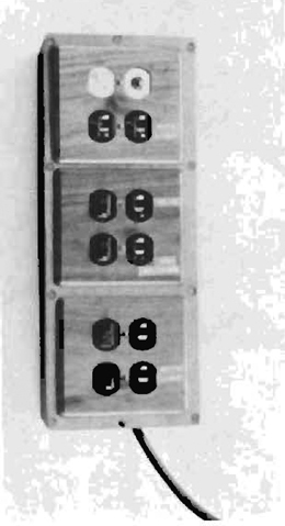
The Assembled Unit. This photograph shows a completely assembled unit built from the plans given on these pages. The top switch (white) is the master power switch that controls all other circuits. At the end of the session in the darkroom, turning off the master switch shuts down all darkroom circuits.
There are two outlets controlled only by the master switch, and four outlets controlled both by the master switch and by their own switches.