4 Designing the Room
Contents
What Are Layouts and Elevations?
Light-Trap and Drying Rack Cutouts
What are Layouts and Elevations?
Designing a Darkroom
A well-designed darkroom requires the completion of a number of planning steps to ensure that the darkroom will function as well after it is built as you had hoped when you first conceived it. The major steps and the order in which they should be completed are:
- Determine the size and type of equipment to be used in the darkroom and the size of prints that will be made.
- Prepare a layout (floor plan), making provisions for all of the items to be used in the room and the print sizes that must be accommodated.
- Prepare elevations to show how storage shelves and cabinets are to be built and at what height the work surfaces are to be located.
- Prepare working drawings for those items that you plan to build yourself or have someone else build for you.
This section will help you follow these steps and ease the burden of making all of your drawings to scale. Before you begin, it might help to explain the terms layout, floor plan, working drawing, and elevations.
Working Drawings
Layouts and elevations indicate the placement of items in a room and the outside dimensions of those items. However, they are not detailed enough to actually build from, unless you are a very experienced carpenter or are willing to make do as you go along. To make the job progress more smoothly, the best course is to prepare working drawings that show the pieces that make up a major unit. Working drawings are shown throughout this book for such items as print-drying racks, sinks, light tables, and so on. If you plan on building something that is not detailed in this book, the drawings we have shown will give you a good idea of how to do your own.
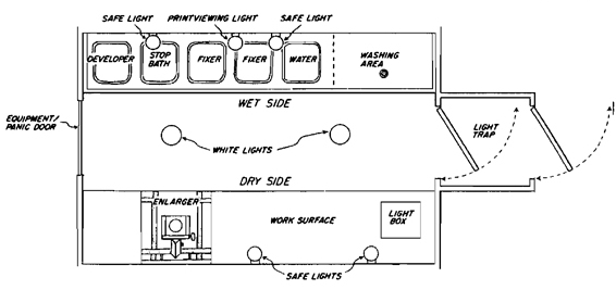
General View. This general view of a typical darkroom gives an idea of what the room would look like if the walls were transparent. The drawing clearly shows the placement of the wet side, the dry side, and other major elements of the darkroom. Although it is very easy to understand, it is difficult to draw, so a more simplified method has been developed to represent the major elements in a room. This simpler method consists of drawing separate sketches to represent the arrangement of items on the floor of the room (the layouts), and on each of the walls (the elevations).
Layouts
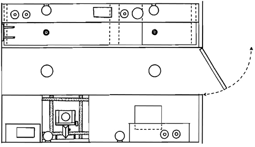
Layouts. If you were directly above the room and peering down through the ceiling from point A in the figure on the opposite page, you would see how items were arranged on the floor of the room. This view is what is called a layout or floor plan, and its preparation is the first step in the design of any living or working space. At this stage, the physical placement of equipment is determined to allow for working comfort by eliminating unnecessary steps.
Wet-Side Elevation
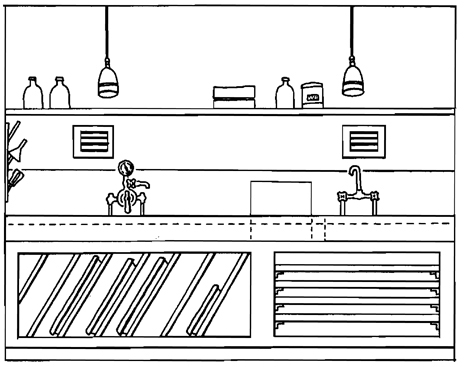
Wet-Side Elevation. If you were to stand outside of the darkroom and look through the transparent wall from point B in the illustration, you would see the wall against which the wet side of the darkroom is built. This view is called an elevation and shows only the fronts of sinks, shelves, and other items on the wall. It is used to plan the placement of equipment and cabinets and should be based on the previously prepared layout.
Dry-Side Elevation
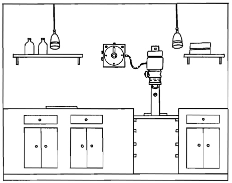
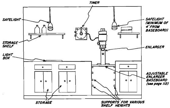
Dry-Side Elevation. Standing outside of the darkroom and looking in from point C would show the dry-side elevation. This elevation will contain the enlarger, dry-side counters, enlarger base, and under-counter storage.
How to Do Layouts
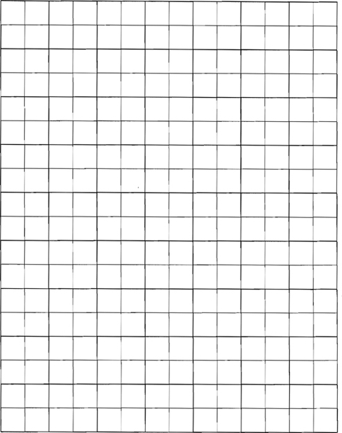
The preparation of a layout is the first step in building any darkroom. This section has been designed to make this preparation as fast and easy as possible. It consists of grids and cutout parts drawn to the approximate scale they will occupy in the actual darkroom. Both the grids and the cutout parts are drawn to a scale of 1/2” to 1’ in the actual darkroom. You might want to make a photocopy of both the grids and cutouts rather than cut up the book.
You can begin your layout in one of two ways. You can either draw the size of the room you plan to use on the grid, or you can assemble all of the elements you plan to use and then draw a room sufficiently large to hold them. The first approach is used when you have a room to convert in which you do not want to change any of the partitions. The second is used when you plan to partition the darkroom off from a larger area such as a basement, and therefore the actual size and proportions of the room are initially unimportant.
If you plan to convert an existing room, start the layout by drawing the outline of the room on the grid. Measure the length of all four walls, then freehand sketch the room outline using one square on the grid to represent one square foot in the room. Next, indicate all existing doors, windows, and other major features in the room, locating them on the drawing in the same scale they represent in the room.
After the room outline is drawn, use the equipment checklist on the facing page to inventory the equipment you have, or plan to have in the future. The amount of material to be accommodated and the size of the prints you plan to make are the key ingredients in planning a workable room. Some of the pieces of equipment directly affect the amount of either counter space or storage space needed in the darkroom, so be sure to make provisions for these items.
All of the major darkroom elements can now be cut out and placed on the grid. The ability to shift and move them about will speed the time it takes to arrive at a final floorplan.
If you plan to include any equipment not provided in cutout form, or if your equipment is to be a different size, you can make your own cutouts by drawing them to the same scale of 1/2” to 1”.
Large Darkroom Layout
Typical Darkroom Layouts. These two darkroom layouts illustrate the extremes that you are likely to encounter. The smaller the space available, the more creative you will have to be. Fitting everything in a large room is relatively easy compared to fitting it into a 3’ × 4’ closet. Both, however, can be done and done well.
Small Darkroom Layout
Before beginning the preparation of the layouts and elevations, it is helpful to make a complete inventory of the materials and equipment that you have or might eventually want to accommodate in the darkroom. It makes good sense to plan ahead and provide space for equipment that will be added during the life of the darkroom. This information is also helpful in planning the type of storage space, sink size, and other elements of the darkroom based on the actual equipment to be used.
Planning Grids
Dry-Side Cutouts
Preparing Layouts: Things to Remember
When working on your layout, there are certain things to keep in mind:
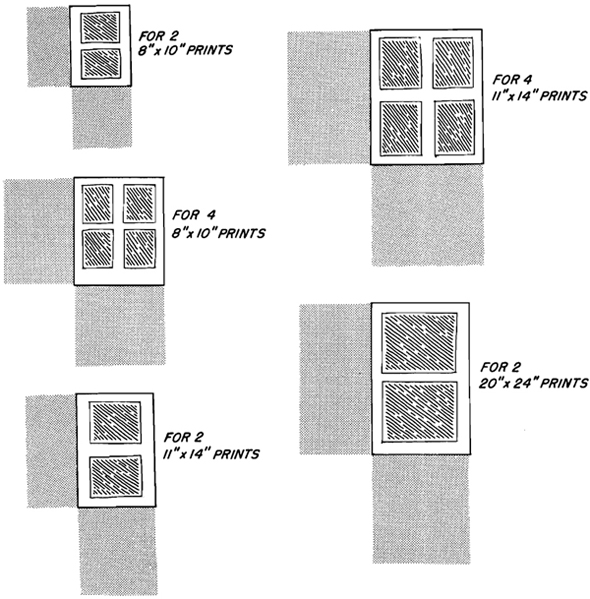
Enlarger. If you plan to make very large prints, the enlarger should be placed where it can be tilted horizontally to project the image on a facing wall. Enlargements of up to 20” × 24” can usually be made by making an adjustable enlarger base (see Chapter 6) or by using a wide-angle enlarging lens.
Aisles. There should always be sufficient room in the aisle to allow for free movement but not so much that additional steps are necessary to move from the enlarger to the sink. Aisle width for a one-person darkroom is whatever is comfortable, usually between 30” and 36”.
Doors and Drawers. Be sure to allow for door and drawer openings. If an aisle is too narrow, cabinet doors and drawers may not open completely without hitting the opposite side. Be sure also to allow for print-drying racks to pull out fully.
Wet and Dry Sides. Where space allows, the dry and wet sides of the darkroom could be on opposite sides of the room, separated by a center aisle. This reduces the possibility of contamination.
Ideally, the developer tray should be located directly opposite the enlarger to reduce the number of steps needed to go from one to the other. If space is not sufficient to separate them with an aisle, a partition of wood can be installed between them to eliminate any possibility of splashing.
Left-Handed? It is recommended that if you are right-handed the room be laid out so that work proceeds from the left to the right (clockwise on the layout sheet), and if you are left-handed it could flow in the opposite direction (counterclockwise).
Exits. All exits should open outward so in case of emergency you can leave the room with the least resistance. Exits should also be sufficiently large to allow for the movement of equipment into and out of the room without tearing down walls.
Size. The size of the darkroom depends, to a large extent, on the size of the prints you plan on making. If you are working primarily with 8” × 10” prints there is a strong likelihood that you will someday want to make larger prints, so accommodate that possibility when planning the room. It’s easier to do it now than to have to rebuild the darkroom later. Darkrooms should not, however, be larger than necessary. A large room only makes you walk farther. The average darkroom will fit well into a space ranging from 6’ × 7’ to 10’ × 12’, regardless of the print sizes being made.
Working Space. Always remember that most equipment also requires working space. For instance, a dry-mount press without a place to have mat board, prints, and dry-mount tissue nearby will be a constant irritation.
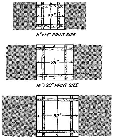
Enlargers. These enlarger cutouts are based on the maximum size of the prints to be made. Enlargers are relatively small compared to the size of the easel, plus the handling room required to make prints of a given size. The enlarger cutouts are also based on the longest dimension of the paper to be used so that both vertical and horizontal prints can be made. If you normally plan on making prints up to 11 × 14 but occasionally make larger ones, you can allow for the larger space with an adjustable easel base (see Chapter 6).
When making an allowance for the enlarger, you should also be generous with the working space on either side. There should be sufficient room for the maximum-sized paper you plan to use, with unexposed paper kept on one side and exposed on the other. The space required can be reduced by installing a light-proof drawer under the enlarger base, thereby eliminating the requirement for counter space to handle it. However, the light-proof drawer will conflict with the adjustable enlarger base unless it is offset to one side.
Paper Cutter
Light Table

Color Processor
Dry-Mount Press
Wet-Side Cutouts
Sinks
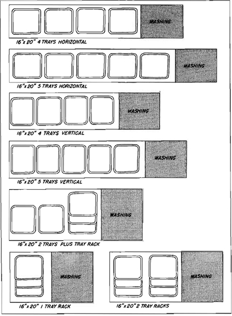
Processing prints requires a minimum of three trays: for developer, stop bath, and fixer. There should also be a fourth tray to be used as a holding-water bath for prints prior to placing them in the washer. Ideally, the sink should allow for a fifth tray to hold fixer, because two-bath fixing is more effective and more economical. The sinks shown here are designed to accommodate anywhere from three trays to six, with an additional 30” space left for washing. If you plan on washing with an East Street Gallery washer or some other such space-saving equipment, the 30” space allowed can be greatly reduced. The sinks vary in size, depending on whether you plan to align your trays in a horizontal or vertical position in the sink, and on the size and number of trays you plan to use. If you plan on building your own sink, and if space allows, you should build the largest size possible to accommodate expansion of your activities. The actual cost of the additional materials and the additional labor required are minimal. If space in your darkroom is at a premium, you can save sink space by using tray racks to hold the trays one over the other.
Sinks for Processing Prints up to 11” × 14“
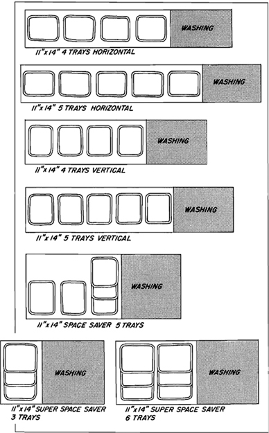
Sinks for Processing Prints up to 16” × 20“
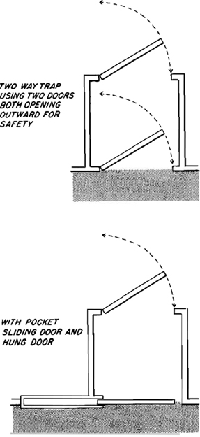
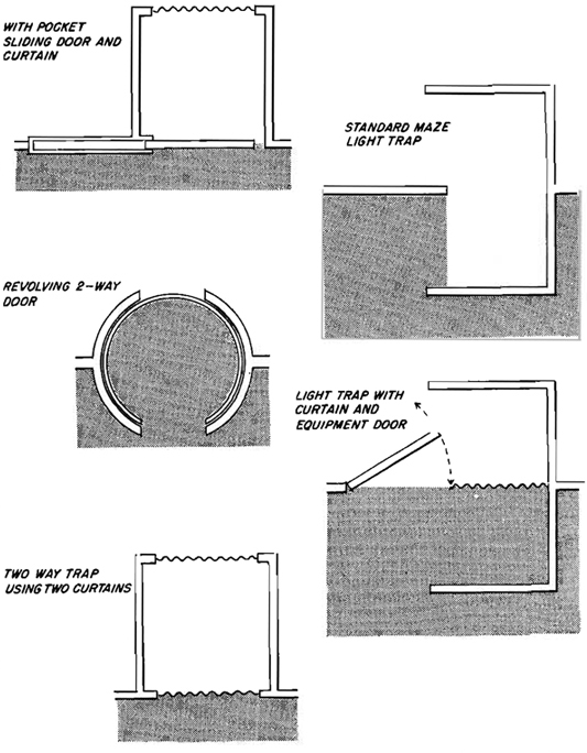
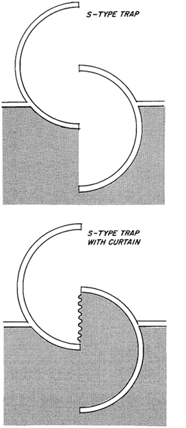
Light-Trap Cutouts
Light-traps allow free access even when light-sensitive materials are exposed. Light-traps are generally a combination of doors and curtains, or mazes that require no doors; the configuration of the walls is enough to prevent light from entering the room.
The inside of a maze or trap should always be painted a flat black to reduce reflections, and tests should be made to ensure that they are light-proof. Film is especially sensitive to light, even minor reflections, and mazes in particular should be watched so that no reflections enter the room to fog the film.
A white line can be painted on the inside walls of any light trap as a guide. All door handles should also be marked with phosphorescent paint. Entering a maze directly out of the bright sun can cause you to be quite blind until your eyes adjust. The white line will enable you to enter without waiting for a complete adjustment. In a short time, you will be able to move around in the dark.
The accompanying mazes have been drawn to scale providing for 30” of shoulder room. The minimum would be about 28”, so slightly smaller designs are possible. A separate equipment door can be constructed in the maze to allow the entry of larger equipment than the light-trap will allow, and it can also double as a panic door. As this door will not be opened regularly, it need not be hinged. A panel attached loosely with small screws is quite effective and can be pushed out if a fast exit is required. Make sure all doors, including the equipment door, open outward for safety.
Light-Trap and Drying-Rack Cutouts
Drying Racks. The drying racks shown here are made with fiberglass screens and wood or metal frames (see Chapter 6). Their capacity should be sufficient to hold prints from a normal printing session. The capacity of the drying rack depends on the horizontal dimensions shown, as well as on the number of shelves allowed by the vertical height available to you. If you normally work in more than one size print, you should build for the larger size. The shaded areas indicate the space needed to pull the rack out either horizontally or vertically. Once you have determined how a given rack will be positioned in your darkroom, you can trim off the shaded area that will not be used.
Preparing Elevations
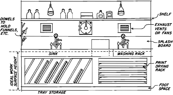
After the layouts for the darkroom have been completed, work can begin on the elevations for the dry and wet sides of the room. Elevations are similar to floorplans except they show the vertical surfaces of the room rather than the floor. To prepare elevations the first step is to measure each wall’s length and height, then outline them on a section of the grid paper using the scale of 1/2” to 1’. When this is completed you will have four rectangles (or squares), each of which represents a wall in the darkroom. Label one of them wet side and one dry side, depending on how they relate to the floorplan. Now draw in all of the existing features of the room that affect the darkroom design, such as door openings, window openings, plumbing outlets, sinks, and so on. These items should be drawn to scale and in their proper location in the room. Measure their size and placement and use the 1/2” to 1’ scale to locate them on the drawings properly.
When the walls have been drawn to scale on the grid, you can begin to plan what the counters and sinks will look like after they are installed. The next step in preparing elevations is to determine the height of the work surfaces in the room. The height of counters, sinks, and enlarger baseboards determines to a large extent how comfortable the darkroom will be to work in. If they are too high or too low, great strain can be put on the back and legs and cut your visit to the darkroom short. Because this decision is so critical it pays to make it wisely. The normal height for work surfaces is 36” above the floor, but this is only a starting point. Comfort while working depends not only on your height but also on the length of your arms and legs. Until all photographers are standardized, darkrooms cannot be.
Begin with the 36” indicated height and make a temporary surface at this suggested height. You can do this by supporting a board with books. Now try to lean on it and move things about. See how comfortable the height is. Strain will show only after a number of minutes have passed, so spend some time to see what your reaction is. If your back is straight and your arms are comfortable, the height will be right for you. If not, raise or lower the board until a more comfortable height is found.
Transfer the ideal working height to the elevations by drawing a line on all wall surfaces to represent that height. Draw another line about 6” above the floor line to indicate the lowest level for the fronts of counters, sinks, drying racks, and so forth. If they go all the way to the floor, there will not be room for your feet as you stand at the counter, and cleaning the room will be much more difficult, because you will not be able to reach under the sink to clean up spilled chemicals.
The Wet Side
The wet-side elevation should show the placement of the sink, shelves, water outlets, safelights, under-sink storage, and, if there is no other space available, the print-drying racks.
The sink bottom should be located at a distance slightly below the ideal working height. The side walls rise about 6” above the bottom, and if the sink is too high it is difficult to reach over the side walls to reach the trays in the bottom of the sink.
Water outlets: Ideally, there will be a regulated outlet at one end of the sink and an unregulated one at the other. Both outlets should be at least 12” above the sink bottom (or above the duckboards, if you plan to use them) so that large graduates can be placed under them to be filled. Even better is to have rubber hoses attached to faucets. When not being used, they lie on the bottom of the sink. In use, they can fill graduates as high as the hose is long.
Storage under the sink can be used to hold processing trays, which can be separated by thin sheets of masonite or plywood. The bottom of this tray-storage rack should slope toward the front to allow for drainage when wet trays are stored. Preferably, trays should be
(continued on next page)
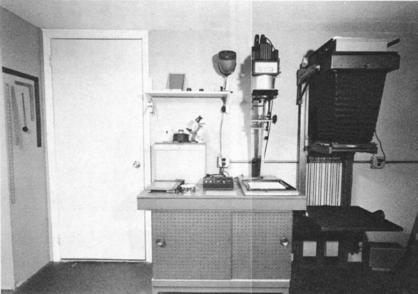
The Dry Side
The dry-side elevation will show the counter, dry-side storage, and the enlarger mount and baseboard. If you plan on using kitchen-type cabinets, they can be drawn in so that their counters are at the height of the line drawn on the elevation to indicate working height. Check to be sure the enlarger head can be raised to its full limit, and use the chart on “Negative-to-Easel Distance” in Chapter 6 to determine if you can make the size prints you normally make at the counter-top height. Perhaps your enlarger head will hit the ceiling before the negative-to-easel distance is sufficient to give you the size prints you normally make. If this happens, you have three alternatives:
(continued on next page)
left tilted on end in the sink to drain completely prior to being stored.
Print-drying racks can be located under the sink if there is no room for them outside of the darkroom (building instructions are shown in Chapter 6).
Dowels can be mounted into the walls on the sides or back of the sink to provide a convenient place to hang graduates, funnels, tongs, and other small items for draining and storage. Be sure to place them where the dripping water will not contaminate processing trays. A small trough can be fashioned under the trays to funnel the water into the sink.
Exhaust vents or fans can be located over the sink to eliminate fumes and water vapor. Never locate a fan that blows air into the room over the sink, since that will just distribute the dust and vapor more widely. The wet side should always be used to exhaust the air out of the darkroom.
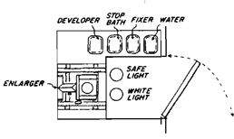
Safelights should be indicated on the elevation and should be no closer than 4’ from processing trays or the enlarger baseboard.
The shelves over the sink should be high enough so that when trays are stood on end to drain in the sink, they will not hit them.
- Cut a hole in the ceiling to allow the enlarger head to rise higher.
- Lower the enlarger baseboard to increase the negative-to-easel distance.
- Use a wide-angle enlarging lens.
Normally the enlarger can be mounted on the wall just above the counter top, or it can be set directly on the counter. You may want to build an adjustable enlarger base to provide for larger prints (see Chapter 6).
Determine the width of the enlarger area based on the maximum-sized easel you plan to use. Locate this area near the developing end of the sink, allowing for room on either side of it for unexposed and exposed paper.