
Why do we need gears? An intuitive answer is to transfer drive from a motor to a receiving mechanism. While true, this is not the complete picture. The essential purpose of gears is to transform the properties of a power input to suit our purposes. Transferring drive is just a side effect of this process.
Gears can be driven by all kinds of inputs, from electric motors and manual cranks to wind turbines and mill wheels. Let’s start by considering gears powered by electric motors because unlike other power inputs, motors have constant, measurable properties.
Every motor has a certain mechanical power, consisting of two factors: rotational speed and torque. These are the two properties we can transform using gears. Both speed and torque are explained in detail in Chapter 1.
When do we need speed? When do we need torque? Each mechanism and model you build has unique needs. Some will need more speed and less torque than the motor provides, and for others, the reverse will be true. Using gears, we can transform torque into speed or speed into torque. There are two very important but very simple rules for this relationship:
Driving a large gear with a small gear increases the torque but decreases the speed. This is called gearing down (see Figure 5-1).
Driving a small gear with a large gear increases the speed but decreases the torque. This is called gearing up (see Figure 5-2).
Speed and torque are inversely proportional: If we decrease the speed by a factor of two, the torque is increased by a factor of two. We can’t transform one property without affecting the other, unless we modify the power input by exerting more force on a manual crank or by providing an electric motor with a higher voltage.
When propelling a vehicle that is light and needs little torque to move, we can transform the abundant torque into extra speed by gearing up. The amount of torque we can transform depends mainly on the vehicle’s weight. Experienced builders can estimate the range of possible transformation knowing just the vehicle’s weight and the type of motor used to drive it.
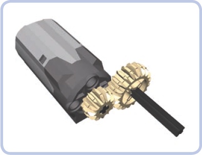
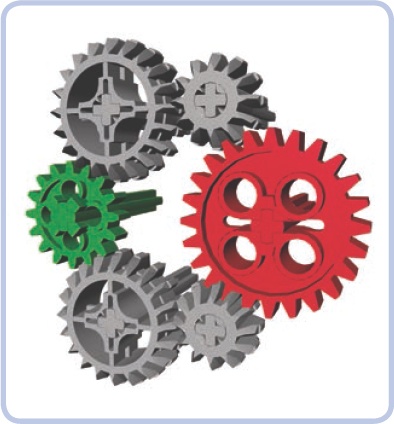
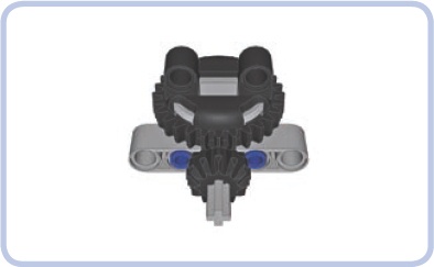
Let’s consider a simple example of a geared power transmission, shown in Figure 5-3, in which the grey motor is connected to a wheel via two gears. The green gear that is closest to the power input (the motor) is called a driver gear. The red gear that receives the drive from the driver gear is called a follower gear.
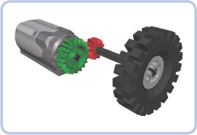
Figure 5-3. Driver and follower gears. Illustrations in this chapter will use the same color scheme: green for driver gears and red for follower gears.
Whenever there is a pair of meshed gears on separate axles, one of the gears is a driver, and the other is a follower. The driver is the gear the drive is transferred from, and the follower is the gear the drive is transferred to.
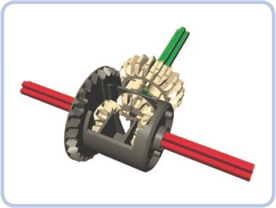
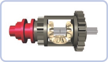
As the gears rotate, so do the axles on which they are mounted. Therefore, a driver axle, called the input, and a follower axle, called the output, follow the rotation of the gears. Most mechanisms have a single input axle, but the output axles can be numerous. The common differential mechanism is a good example of one input with many outputs (see Figure 5-4).
In addition to driver and follower gears, we have idler gears. If there is a set of gears in a series, the first one is the driver gear and the last one is the follower gear. All the gears in between are called idler gears (see Figure 5-5), because they could just as well not exist. In other words, they don’t affect how the torque and speed are transformed.
Figure 5-5. Three gears meshed one by one, with the idler gear in grey. The idler’s axle serves only as its mounting point.
Idler gears are typically meshed with two or more gears at the same time, while the driver and follower gears are meshed only with one, as shown in Figure 5-6. Exceptions to this rule are shown in Figure 5-7.
Figure 5-6. The middle gears in this picture are idler gears. Both are meshed with only one gear, but they are mounted on the same axle and are of exactly the same size, which means that they work just as a single gear would.
Figure 5-7. The middle gears in this picture are not idler gears. Both are mounted on the same axle, but they are of different sizes, which means that they affect how torque and speed are transformed. This is because the varying size of the gear affects the torque it transfers.
Note that idler gears should be used only when absolutely necessary, as they add friction and need to be properly supported. An excess of idler gears is shown in Figure 5-8.
A gear ratio is the relationship between the number of teeth in two interacting gears. Interacting gears might refer to two gears that are meshed or otherwise connected, two gears connected by a roller chain, or even two pulleys connected by a drive belt. The gear ratio of two sprockets connected with a chain is exactly the same as the gear ratio of those sprockets directly meshed.
A gear ratio is defined as follows: number of follower gear’s teeth : number of driver gear’s teeth.
For instance, if we drive a 24-tooth gear with an 8-tooth gear, the gear ratio, also known as the torque ratio, is 24:8. Know, however, that we should reduce both numbers in a gear ratio until one of them is 1. To do this, we need to find a divisor, usually equal to the smaller number. As you can see here, if we divide both numbers in a 24:8 gear setup by 8, we will get a 3:1 ratio, which is much more convenient and immediately shows us that three revolutions of a driver gear result in a single revolution of a follower gear.
So what good is this ratio? We can use it to easily calculate how speed and torque are transformed between the two gears. Looking at the 3:1 ratio, we can tell that the speed is reduced by a factor of three, and since the decrease of speed results in an inversely proportional increase of torque, we know that torque is tripled.
Now consider an example where the driver has more teeth than the follower: We have a 20-tooth driver gear and a 12-tooth follower gear. The gear ratio is 12:20, which is equal to 0.6:1. This means that we need 0.6 revolutions of the driver gear to get a single revolution of the follower gear, so the speed is increased, but at the same time the torque of the follower is 0.6 of the driver’s torque, so the torque is decreased.
Our gear ratio also reveals whether we’re gearing down or gearing up. If the first number of the gear ratio is greater than the second (as in 3:1), we are gearing down—this is also called gear reduction. If the first number of the gear ratio is smaller than the second (as in 0.6:1), we are gearing up—this is also called gear acceleration or overdrive. If we have a 1:1 gear ratio, speed and torque remain the same.
What if we want to calculate the total gear ratio of a mechanism with many pairs of meshed gears? In this case, we ignore all the idler gears and calculate ratios for all pairs of driver and follower gears. Then, in order to get the final gear ratio of the entire mechanism, we simply multiply these gear ratios. Consider a mechanism with two pairs of 8-tooth drivers and 24-tooth followers. The gear ratio of the first pair is 3:1, and so is the ratio of the second pair. If we multiply these ratios, we get the final ratio of 9:1.
Now that we can calculate gear ratios, let’s go back to the previous examples showing idler and non-idler gears.
Consider the first set of gears, shown in Figure 5-6. It consists of two pairs of gears: a 12-tooth driver with a 20-tooth follower and a 20-tooth driver with a 12-tooth follower. The ratio of the first pair is 20:12, and the ratio of second pair is 12:20. If we multiply these, we get the final ratio of 1:1. The idler gears did not change the ratio at all.
Now consider the second set of gears, shown in Figure 5-7. It consists of two identical pairs of gears, which have a 12-tooth driver with a 20-tooth follower. The ratio of each pair is 20:12, and if we multiply these, we get the final ratio of 2.779:1, which is not equal to 1.667:1 (the ratio of the first and the last gear only). Here, the middle gears are not idlers—they affected the final gear ratio of the whole set—and they can’t be ignored.
Finally, how do we calculate the ratio if a worm gear is used? Well, that’s even simpler: number of follower gear’s teeth : 1. That’s because a single revolution of a worm gear rotates the follower gear by a single tooth. For example, it takes 24 revolutions of the worm gear to rotate a 24-tooth gear fully, and hence, we get the ratio 24:1.
Every gear we use has its weight and generates friction that has to be overcome if we want the gear to rotate. Every gear in our mechanism dissipates part of the drive motor’s power, and the efficiency of the gear tells us how much power is fully transferred and how much is lost. Unfortunately, it’s extremely difficult to calculate the individual efficiency of each gear, especially since gears wear over time. We do know, however, how power is lost in mechanical systems, so we can safely assume two basic rules for maximum efficiency:
The fewer the gears we use, the better.
The smaller the gears we use, the better.
In practice, low efficiency results in a loss of torque and speed. This loss happens because low efficiency generates resistance—resulting from friction, among other things—that a motor has to overcome. You can see this with motorized vehicles; in most cases their wheels rotate faster when you lift them off the ground. All of this means that the real, functioning mechanism is never as effective as the gear ratio alone indicates, and how much its efficiency is diminished is determined by the efficiency of the gears.
You can see the importance of efficiency in any mechanism that includes a worm gear. A worm gear’s extremely high gear reduction comes at the cost of efficiency. Some sources estimate that a worm gear loses almost one third of the motor’s power due to high friction and the gear’s tendency to slide along its axle. The friction is high enough to make worm gears hot if they handle high torque for a prolonged period of time, and the friction is also the reason why LEGO worm gears can’t be follower gears. Worm gears are irreplaceable for some applications, but in general, they should be used in moderation.
For LEGO gears, we can simply assume that backlash is the free space between the meshed teeth of two adjacent gears. In an ideal situation, there would be no free space at all, but in practice, LEGO gears always generate some backlash. The general rules are as follows:
Old-type gears generate much greater backlash than the new bevel gears.
The smaller the gear, the greater the backlash.
The backlashes of any directly meshed gears sum up.
Why is backlash so bad? Consider, for example, any steering mechanism: Any significant backlash between it and the motor that controls it will not only degrade the accuracy of steering but also make the wheels have some margin of freedom so that they may turn a bit when they meet an obstacle. This may cause your vehicle to waver out of a true straight line as it navigates bumps or create a noticeable delay as you steer a vehicle.
Backlash can become troublesome whenever accuracy is needed. Many sorts of cranes, drawbridges, and turntables suffer from backlash. The best way to avoid backlash is to use pneumatics instead of mechanics (see Chapter 9) or to use linear actuators, which currently have the least backlash out of all the mechanical parts produced by LEGO (see Chapter 13).
How does backlash work with a worm gear? Again, this gear proves unique in generating nearly no backlash—except for the fact that it can slide along the axle a bit, being slightly narrower than 2 full studs. Now, that doesn’t mean that mechanisms with the worm gear have zero backlash—unfortunately, there is still backlash from the follower gear. Therefore, a mechanism with a worm gear and a 16-tooth follower gear will always have greater backlash than one with a worm gear and a 24-tooth follower gear. And again, it is recommended that you use a worm gear with bevel gears due to their relatively insignificant backlash.
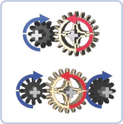
When gears are meshed directly, the driver gear affects the follower gear’s direction of rotation. Whether the follower rotates in the same or in the opposite direction as the driver depends on the number of gears between them. When gears are in a parallel series, the rule is simple: With an even number of gears (2, 4, 6, and so on), the follower rotates in the opposite direction, and with an odd number of gears (3, 5, 7, and so on), the follower rotates in the same direction (see Figure 5-9). You may find yourself adding or removing idler gears to adjust the follower’s direction.
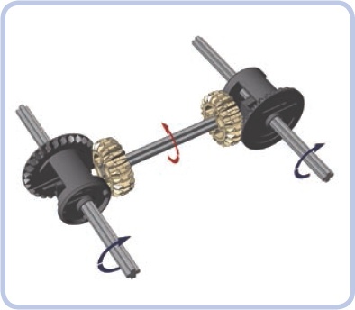
Direct observation may be the quickest means of determining the output rotation of gears that mesh perpendicularly. For example, in a 4×4 vehicle’s drivetrain with a longitudinal driveshaft, the front and real differentials must be oriented in opposite directions for the front and rear wheels to rotate in the same direction, as shown in Figure 5-10.
LEGO has released various types of gears throughout the history of the Technic line. The gears can be divided into a few different groups, and we will discuss them group by group. First, we’ll examine the most common and familiar gears.
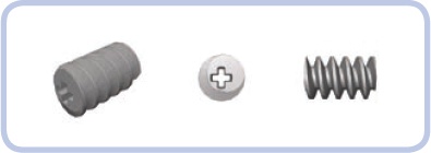
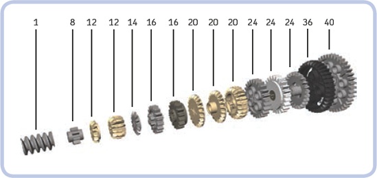
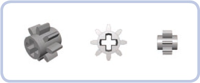
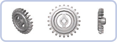
As you can see in Figure 5-11, the group of common and familiar gears consists of one special gear called a worm gear (first on the left), five gears of a new type called bevel gears (tan), and nine old-type gears (presented in their most common colors). Despite their differences, almost any two of these gears can be meshed together. The unique property of the bevel gears is that they can be meshed in both a parallel and a perpendicular manner. Their size makes them better suited for use in studless constructions, while the shape of their teeth makes it impossible to put LEGO chains on them.
Note
The names of types of gears, such as 8-tooth gear and 24-tooth gear, can be shortened to g8t and g24t, respectively. These so-called straight-cut gears are also known as spur gears.
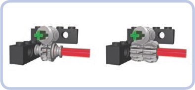
This special gear has a number of unique properties. First, it is impossible to drive a worm gear with any other gear; a worm gear can be used only as the driver gear, never as the follower gear. The worm gear comes in handy for mechanisms that need to lift something up and keep it raised; in this case, a worm gear acts like a lock that, once stopped, keeps its follower gear immobile, resisting any load on it. This is useful in building cranes, forklifts, railroad barriers, drawbridges, winches, and basically any mechanism that needs to keep something steady once the motor stops. Second, the worm gear is extremely useful for gearing down.
Every revolution of the worm gear rotates the follower gear by just a single tooth, reducing speed and increasing torque drastically. Therefore, worm gears are used for gearing down whenever very high torque or low speed is needed and there is little space to use.
Finally, as the worm gear rotates, it has a tendency to push against the follower gear and slide along its own axle. Usually this tendency has to be stopped by placing a strong casing around the worm gear, but there are certain mechanisms that put it to use (see Chapter 8 and Chapter 10 for examples).
Despite its unusual appearance, the worm gear can drive any other gear from the group. With proper spacing, it can drive bevel gears, too (see Figure 5-12).
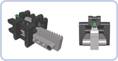
It’s even possible to use the worm gear to drive racks, which results in a very compact boom-extending mechanism (see Figure 5-13), which could be useful in a crane or a telescoping forklift, or any other application where space is at a premium.
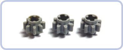
This is the smallest LEGO gear in existence, and it’s a fragile one. It’s not suited for high torque, but due to its size, it’s very popular, especially for gearing down. The 8-tooth gear has the disadvantage, however, of generating extremely significant backlash.
There are at least three variants of this gear coming from three slightly different molds (shown in Figure 5-14). The initial variant of the 8-tooth gear has thin teeth around a thin central ring, which is called back iron. The later, middle variant has the same central part, but its teeth are shorter, thicker, and presumably stronger. The third variant is the one most sought after, but it is unclear when it was in production and in which sets it was included. It maintains the shape of the teeth introduced in the middle variant, but its central part has an extra layer of material between the teeth, adding to its thickness. This change is clearly intended to prevent the teeth from bending under torque, thus making the entire piece significantly stronger.
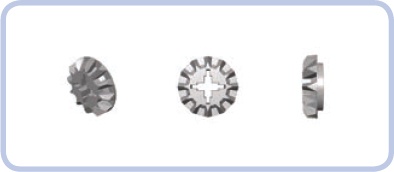
This is the smallest of all bevel gears and the most fragile one. But it’s irreplaceable in differential mechanisms, and it’s very popular when there is a need to transfer the drive in a perpendicular manner inside a tight space. It’s easily broken under high torque, which has led many builders to exclude differentials completely from their off-road vehicles.
This gear is much stronger than its single-bevel counterpart, and it’s most often used with a double-bevel 20-tooth gear. It doesn’t fit inside differentials or in tight spaces, which makes it less popular for perpendicular meshing.
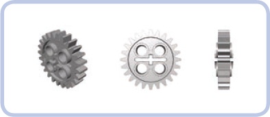
The first gear used inside differentials, this gear proved so fragile that it was later replaced by the 12-tooth version. It is no longer used in the official LEGO models and is unpopular with builders.
This is a reasonably strong and useful gear. This is the smallest gear that can be operated with a LEGO chain, and it’s a popular one thanks to its convenient size. As of early 2011, it was replaced in LEGO sets by a slightly updated version (see Figure 5-15). The shape of the new version’s outer rim is exactly the same, whereas the structure in the middle of it has been reinforced. The new version is generally more massive and therefore more torque resistant.
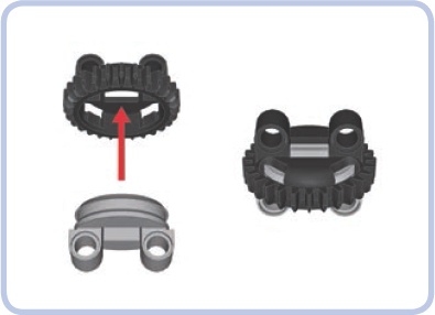
This gear was designed specifically for gearboxes. It’s weaker than the regular version and doesn’t work well with a LEGO chain because its shorter teeth make the chain slip. Instead, it has the unique ability to be engaged or disengaged by the transmission driving ring (see Figure 5-16). Without the ring, it remains loose on the axle, but it can be meshed with an old-type half bush (the one with teeth) and thus get fixed to the axle (see Figure 5-17). In 2011, it started being phased out and replaced by a newer version without teeth (see Figure 5-18).
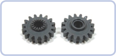
Figure 5-18. The toothed (left) and toothless (right) variants of the 16-tooth gear with clutch. Both variants wear the same number, which means that LEGO considers them to be basically the same piece. The most likely reason for the change from toothed to toothless is the fact that all pieces the teeth could be meshed with have been long out of use in LEGO Technic sets.
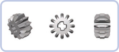
This is a larger version of the single-bevel 12-tooth gear. It is relatively rare and not really popular because of its thin body, which makes it prone to snapping under high torque.
This modification of the single-bevel 20-tooth gear was intended to offer some new possibilities rather than to replace it. These possibilities include the ability to rotate freely on an axle so that the gear can be used to transfer drive “over” the axle without driving it and without adding the axle’s friction to its own. The new gear also has a half-stud-thick collar at its base, which makes it remain on the axle more securely. It is much less likely to snap than the single-bevel 20-tooth gear, but it can act only as an idler gear.
This is a very popular, strong, and reliable gear. It’s most commonly used with a single-bevel 12-tooth gear, but it’s useful in other setups, too.
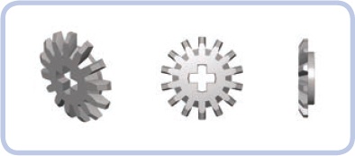
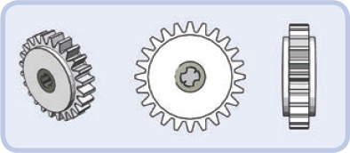
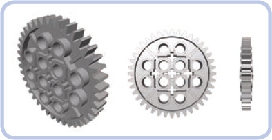
There are at least three variants of this popular, strong, and reliable gear, the newest ones being the strongest ones (see Figure 5-19). The 24-tooth gears are some of the most useful gears available.
This 24-tooth gear is white with dark grey in the center, and it has the unique ability to harmlessly slip around the axle if a sufficiently high torque is applied. It’s most often used for end-to-end applications—that is, applications in which the motor can run only until it reaches a certain point. This includes almost all steering mechanisms, in which the wheels can be turned only within a limited angle, and the railroad barrier mechanism, by which the barrier can be raised or lowered only to a certain degree. In these types of mechanisms, the gear slips when that end point is reached so that the motor can continue to run while the mechanism itself is stopped. This gear is also used for the motorized winches in official LEGO sets, where it ensures that the motor doesn’t get damaged when the end of the winch’s string is reached. Note that this gear slips under a very specific amount of torque, and in most cases, you will want it to slip only under extremely high torque (in other words, you’ll need to make sure that the steering mechanism stops turning when the end point is reached, not merely when a wheel meets an obstacle). This can be achieved by adding some gearing down between it and the mechanism it controls (see Figure 5-20).
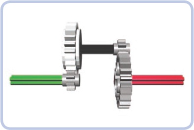
Figure 5-20. An example of the 24-tooth gear with clutch being protected by gearing down (right). The gear ratio is 3:1, which means that the gear is subject to just a third of the overall torque, thus requiring three times the amount of torque to slip.
LEGO builder Jetro de Château discovered that there have been at least three versions of this gear released over the years: one that came with the 8479 set, which has a light grey center and requires more torque to slip; one that is most commonly used, which has a dark grey center; and one that is from an unknown set or sets, which has no inscriptions on its sides.
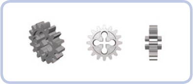
This crowned gear was the first gear among the regular gears that could be meshed in a perpendicular manner. Again, there are at least three variants of this gear, the older and weaker ones having been gradually replaced with newer and stronger versions. The arrival of bevel gears made this gear unpopular: It’s weak and inconvenient to use due to its shape and protruding central hub.
This is the largest bevel gear and the only one with no single-bevel counterpart. A convenient and surprisingly strong gear, though a rare one, it usually comes in black.
This is the largest gear of all. While rare and rarely used because of its immense size, it is popular in tracked models as a sprocket wheel for the old type of tracks.
LEGO has produced three different differential gears. Let’s review them starting from the left in the figure above:
- old-type 28-tooth differential gear
The oldest differential gear, it’s designed for use with 14-tooth gears inside but also compliant with the single-bevel 12-tooth gears. It takes a lot of space and comes with 28 teeth that can be meshed in both a parallel and a perpendicular manner. It always comes in light grey.
- 16/24-tooth differential gear
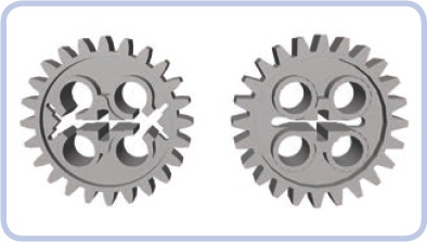
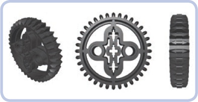
The successor of the older differential gear, it is much more universal and can be used in situations where other differential gears cannot be. It includes two gears, one with 16 teeth and one with 24 teeth, both of which can be meshed in a parallel manner only. The 24-tooth gear can be driven with a LEGO chain. Additionally, both ends can be engaged by a transmission driving ring, locking the differential (see Figure 5-21). It comes almost exclusively in dark grey.
- new-type 28-tooth differential gear
This variant was introduced with the growing popularity of studless constructions, in which a differential of even width is difficult to incorporate. It has 28 teeth that can be meshed in a perpendicular manner only, and it’s just 3 studs wide. Much less massive than the other differentials, it is surprisingly strong, especially when enclosed inside a 5×7 studless frame that was designed specifically for it (see Figure 5-22). Its inside is redesigned to work with the single-bevel 12-tooth gears only, and it includes a special structure that keeps them in place more securely.
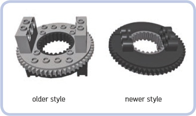
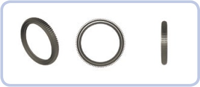
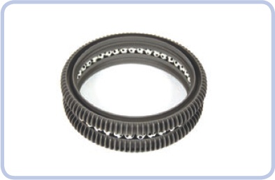
LEGO Technic turntables come in big and small versions. There are two variants of the big one, with the only real difference being the fact that the older style (left) is suited for studfull constructions, while the newer one (right) is suited for studless ones. Additionally, the older one is 4 studs tall, and the newer one is 3 studs tall. The outer ring of both turntables has 56 teeth. The inner one has 24 teeth and is the exact size of the 24-tooth gear; however, the construction of the studless turntable makes it impossible to put a 24-tooth gear inside it. Still, a turntable can be meshed with smaller gears.
Both variants consist of upper and lower halves, which can get separated if sufficient force is applied. The outer ring is most often driven by an 8-tooth gear or a worm gear. The turntables can be used in a normal or an upside-down position (the studless one is better suited for an upside-down position), depending on whether we want to drive them from above or below.
As of 2012, a small turntable has been introduced. It consists of two halves (see Figure 5-23), each with two pin holes, and it has a ring of 28 teeth attached to one of the halves. One side of the teeth is chamfered, as in bevel gears, and the other one is unaltered, as in straight-cut or spur gears. Therefore, the turntable can be engaged by bevel gears only from the side of the toothless half, as shown in Figure 5-24. The combination of gears that can be used with this turntable is limited, with the single- or double-bevel 12-tooth gear clearly being the best-suited one.
The small turntable is 3 studs tall, and its diameter is slightly over 3 studs: exactly 28 mm. The hole in its middle has a shape of 1×1 studs square, which means that we can put the following through it: an axle, even with a bush or an axle joiner on it; a universal joint; the rod of a pneumatic cylinder or of a linear actuator; up to four pneumatic hoses; or even a beam, although the beam’s square profile will stop the turntable from rotating. What we can’t put through a small turntable are wires—because their plugs are too big—and LEGO LEDs, which are also too big.
This is an important and popular piece, even though it’s technically not a gear. Knob wheels can mesh only with other knob wheels, in both a perpendicular and a parallel manner. To their advantage, they are much stronger than gears, and they can handle significantly higher torque. They are most commonly used in the perpendicular setup because the regular gears that can transfer the drive in such a setup are much more likely to snap under torque than the knob wheels are. The disadvantage of knob wheels is that the unique shape of their teeth makes them work unevenly. This is particularly apparent when a large torque is applied to a perpendicular setup of knob wheels—their speed of rotation starts to fluctuate. Also, because all the torque is applied to so few points, knob wheels are prone to wearing out. It is not uncommon to see knob wheels rub away at their meshing points, but this happens only with really heavy loads and only after a while.
This is a very large and very rare gear. It has an impressive diameter equal to 26 studs, and it has 168 teeth on the inner ring. The whole gear is 3 studs thick, its inner teeth are 1 stud wide, and it has 1-stud-deep troughs on both sides. This makes it relatively easy to drive, either by building some structure inside it or by attaching it to an external structure.
The gear got its name from the only set it appears in: It’s the wheels of the 4481 Hailfire Droid. Since the set is no longer produced and there were only two gears of this type included in each set, they have become rare and expensive.
Hailfire Droid wheel gears are highly desired for use as turntables in very large models. With two gears like this, it is possible to put them on top of each other, filling the troughs on their facing sides with up to 41 LEGO balls (see Figure 5-25). The resulting mechanism acts like a ball bearing, which makes it capable of rotating under significant loads; additionally, the sheer size of the gear makes it very stable.
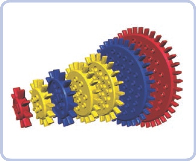
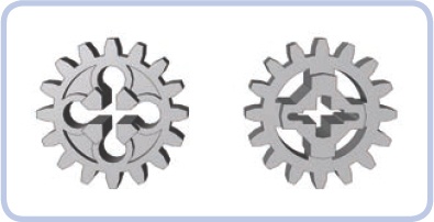
These odd and colorful gears are parts of two early systems of LEGO gears: the Samsonite system introduced in 1965 and the Expert Builder system introduced in 1970. They are predecessors of today’s Technic system, which replaced them in 1977. These gears have been absent from LEGO sets since then, but they’re still relatively easy to find in secondhand sales. They mesh in both a parallel and a perpendicular manner but only with the gears from their own group. Just like knob wheels, they have teeth that make them work unevenly. Note that they are massive and made from very durable material, and some even have metal centers, which makes the smallest of them popular with builders seeking heavy-duty gears. The larger ones are rarely used because of their enormous size.