Adders and subtractors are mechanisms used to couple two or more motors together. Coupled motors are usually used to control a single function, most often the propulsion of a vehicle. They can work together (in an adder) or against each other (in a subtractor). Both mechanisms make use of differentials, and both are examples of advanced mechanics. The way subtractors work is particularly fascinating.
You’ll find that using adders is a great way to give your motor even more power. Subtractors will be most useful when building tanks and construction vehicles, as these mechanisms have two outputs perfectly suited for controlling two treads.
But first, let’s consider a simpler solution to coupling motors, one that forces two motors to run at the same speed. Making such a connection is called hard-coupling (see Figure 18-1).

Forcibly slowing or speeding up a motor can be harmful and may permanently degrade its performance. Still, hard-coupling isn’t that different from a LEGO motor’s regular use, where motors are slowed down by a load or sped up by a vehicle rolling downhill. Hard-coupling two or more motors of the same type is a fairly low-risk solution for increasing your model’s power. But what if we want to couple motors of different types or if we find hard-coupling too risky? This is where adders come in.
Note
The performance of identical electric motors can vary, making their speeds differ by a few percent. This is because every motor includes moving parts that are prone to wear, and the precision of the motors’ production process can vary between batches.
Adders couple two motors to work as one; in doing so, adders sum the motors’ individual torques. As a result of this coupling, the output will be the average of the two motors’ rotational speeds. This means that we can use two coupled PF Medium motors in cases where one Medium motor is too weak and an XL motor is too large.
An adder makes use of a differential in order to equalize the differences between two or more inputs and to drive a single output. A differential has three elements that can be used as inputs or outputs: the two axles that come out of it and the case of the differential itself, as shown in Figure 18-2.

Figure 18-2. A differential that includes two axles (green and blue) and the differential case (red)
A differential consists of a housing with three bevel gears inside, two of which are set on two axles that enter it from opposite sides. The third gear is connected to the housing only. The first two gears are called spider gears or side gears, and the gear fixed to the housing is called a planet gear.
When a differential is used to couple motors, any difference between inputs will be equalized by the system of the differential’s inner gears. The output will be driven by the sum of the inputs’ torques and the average of their speeds. Figure 18-3 through Figure 18-6 show some examples of two motors coupled with an adder in various ways. The biggest distinction among these variations is the use of different differentials. The motors’ inputs are blue and green, and the adder’s output is red.

Figure 18-3. Two PF Medium motors are driving the differential case (blue) and one of the axles (green). The other axle (red) is the output.


Note
When using adders, always try to have similar gear ratios between the motors and the adder. Differences in gear ratios will make the motors share the load unevenly, with one motor working harder than the other. The gear ratio immediately after the adder (that is, between the adder and the mechanism it drives) does not affect the load distribution.
You already know that an adder sums the torques of its inputs and averages their speeds, but let’s express these relationships mathematically. If we have one motor, motor1, and another motor, motor2, then the adder’s torque is equal to
| torque(motor1) + torque(motor2) |
and if n is the total number of motors, the adder’s speed is equal to
One important consideration when building adders is the direction each input rotates. Coupled motors are usually powered from the same source, resulting in an identical direction of rotation. But depending on whether the inputs’ directions match, the two motors can work together or against each other. The latter case is obviously undesirable, as it results in decreased torque and speed.
All the examples shown above have motors running in the same direction; however, in some cases, it’s convenient to have the motors oriented so that they run in opposite directions. For the adder to work properly in such a case, we need to reverse the direction of one motor, either by powering it from a power source with the opposite polarity or by connecting it to a shared power source through a switch (shown in Figure 18-7). With older 9V motors, you can reverse the polarity of a motor by simply rotating its wire connector 90 degrees.
Figure 18-8: These two adders won’t work properly unless we change one motor’s rotational direction.


In most cases, coupling two motors will give us enough torque, but what if we want even more torque? We can use an adder to couple more than two motors, but unfortunately the mechanism’s size and complexity will increase dramatically since every motor beyond two requires one more differential (see Figure 18-9).

Each differential other than the first one has one input already taken, as it’s connected to the previous differential (the second differential is connected to the first one, the third to the second one, and so on). Thus, we are left with only one free input, and we can add only one motor for each differential. Unfortunately, the resulting high torque makes chaining adders in this way fairly risky.
When more than two motors need to be coupled, it’s usually a better choice to use motors of the same type and hard-couple them. This is true not only because it takes less space but also because with more motors, there is more torque to transfer, and differentials are not fit for handling high torque. Hard-coupling with knobs (shown in Figure 18-10) is a reasonable alternative.

Subtractors combine the power of two motors in a more complex way. Each subtractor has two inputs and two outputs and also uses two differentials. Rotating one input of a subtractor makes both outputs rotate in the same direction; rotating the other input makes the outputs rotate in opposite directions. Both inputs can be rotated at once, making the outputs rotate at different speeds.
It’s easier to understand how a subtractor works when thinking of its most common use: driving tracked vehicles. A typical tracked vehicle has two tracks: left and right, as shown in Figure 18-11. When both tracks rotate in the same direction, the vehicle moves forward or backward along a straight line. When the tracks rotate in opposite directions, the vehicle turns in place. When the tracks rotate at different speeds, the vehicle makes a wide turn, as a car would, and the greater the difference between motor speeds, the tighter the turn.

With tracked vehicles, we can assume that one of the subtractor’s input motors is for driving and the other is for turning. Let’s call them D and T, respectively, and note that D is usually faster than T. If only D is running, both tracks (that is, both outputs) rotate in the same direction, making the vehicle drive straight. If only T is rotating, both tracks rotate in opposite directions, making the vehicle turn in place. Now, an interesting thing happens when both D and T are running at the same time: One track rotates at D + T speed, and the other at D − T speed. Depending on how much these speeds differ, each track can rotate very slowly (D > T), stop completely (D = T), or rotate in the opposite direction (D < T). Figure 18-12 shows how D and T affect the motion of a vehicle.

Figure 18-12. The path of a tracked vehicle with subtractors’ inputs being driven. D represents the driving motor (faster), and T represents the turning motor (slower).
By adjusting our inputs’ speeds, we can achieve any combination of the tracks’ speeds: Each track can be stopped or can rotate forward or backward at a speed ranging from almost zero to the sum of the speeds of both inputs.
Note that the relationship between the motors’ maximum speeds affects the way the subtractor works. As an example, let’s imagine we have a vehicle driving straight at full speed and we start turning at full speed. There are three possibilities:
If the speed of D is greater than that of T, neither track will be stopped or reversed; one track will slow down, and the other will accelerate. The vehicle will start turning along an arc while continuing to drive in the same direction.
If the speed of D is equal to that of T, one track will stop, and the other will accelerate; the vehicle will start turning almost in place, with the stopped track being the center of the turn.
If the speed of D is less than that of T, one track will be reversed, and the other will accelerate; the vehicle will start turning almost in place, with the center of the turn located between the tracks at a point proportional to their speeds (closer to the slower track, farther from the faster one).
The difference between the maximum speeds of D and T is a crucial consideration when selecting motors and gear ratios to drive the subtractor. Usually, the first of the three cases listed above (with the faster drive motor and the slower steering motor) is the most realistic and convenient case: A vehicle that goes straight faster than it turns is easy to control and behaves real tracked vehicles do.
Also, the turning input’s speed is very important when a vehicle is turning in place. The tracks rotate in different directions, so the difference between the two tracks’ speeds is equal to twice the turning input’s speed. Applying too much turning speed will make our vehicle look like a carousel rather than, say, a tank. Additionally, turning in place involves significant friction, as the tracks scrub the ground over a large area. Therefore, it’s a good idea to use gear reduction on the turning input, sacrificing speed for torque.
As you might imagine, a tracked vehicle can be driven with two separate motors as well: one motor driving the left track and the other driving the right track. Using a subtractor takes two motors, too, but has several advantages:
| better control A vehicle with a subtractor can drive in a perfectly straight line, while a vehicle with two separate motors is sensitive to differences between the motors’ speeds and to its own weight distribution, which can weigh down the motors unevenly. |
| lower power consumption In a subtractor, one motor is for driving, and the other is for turning; therefore, we can use two different types of motors together. Driving, tracks separately, on the other hand, requires two identical motors, and two strong motors have a higher total power consumption than one strong motor and one weak one. |
| more mechanisms Connecting another mechanism (a replica piston engine or a rotating fan in the engine bay, for example) to the drivetrain is easy with a subtractor, as it has one motor used specifically to drive. When two separate motors are used, connecting a mechanism to both of them is impossible, and connecting a second function to one motor can slow it down, resulting in a mismatch in speed. |
| better remote control Without a subtractor, you need the Power Functions remote with speed control dials to make the vehicle turn in an arc. The regular Power Functions remote will only be able to make the vehicle drive straight or turn in place. |
The advantages of a subtractor are somewhat diminished if you have the Power Functions remote control with speed dials, which enables a driver to control the speed of each track independently. There are also some disadvantages to subtractors that should be taken into account at all times. First, a subtractor is relatively large and complex, requires plenty of parts, and adds to the vehicle’s weight. Second, a subtractor relies on differentials, which can be damaged by high torque. My experience shows that using a subtractor to drive a vehicle heavier than 3 kg involves a serious risk of breaking the bevel gears inside the differentials, regardless of the gear ratio between the subtractor and the sprocket wheels. The other disadvantage to subtractors is that they don’t give you the power benefit of having two drive motors.
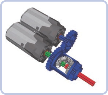
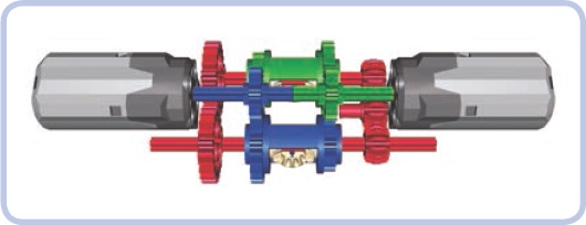
A longitudinal subtractor’s elongated, narrow shape makes it a good choice for tracked vehicles that have long, narrow hulls between their tracks. Figure 18-13 shows the driving input (D) in blue, the steering input (T) in green, the outputs in red, and the sprocket wheels driving the tracks in yellow.
Notice that each motor drives both differentials at once. The PF XL motor drives with a 1:1 gear ratio. The PF Medium motor turns with a 9:1 gear ratio. That ratio makes the turning input’s speed slower than the driving input’s speed, even though the Medium motor’s rotational speed is faster than the XL’s. The driving input rotates at 146 rpm (the normal speed of the XL motor), and the turning input rotates at 30.6 RPM (that is, the speed of the Medium motor reduced by a factor of 9).
Obviously, a subtractor can work with different combinations of motors and gear ratios; the one shown here exemplifies this and is the most efficient combination for most uses. If you use the right gear ratio at the sprocket wheel, you can easily use a single XL motor to drive a 2 kg vehicle. However, a vehicle’s efficiency at heavier weights depends greatly on the type of surface the model is driving on. To achieve more power for heavier vehicles, you can connect more than a single motor to the driving input, for example, by using an adder.

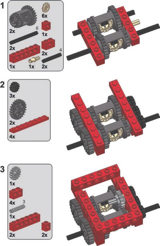
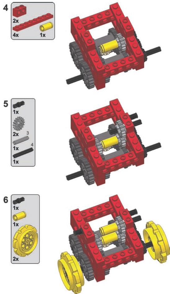
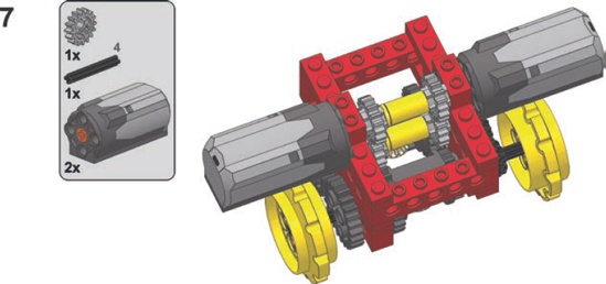
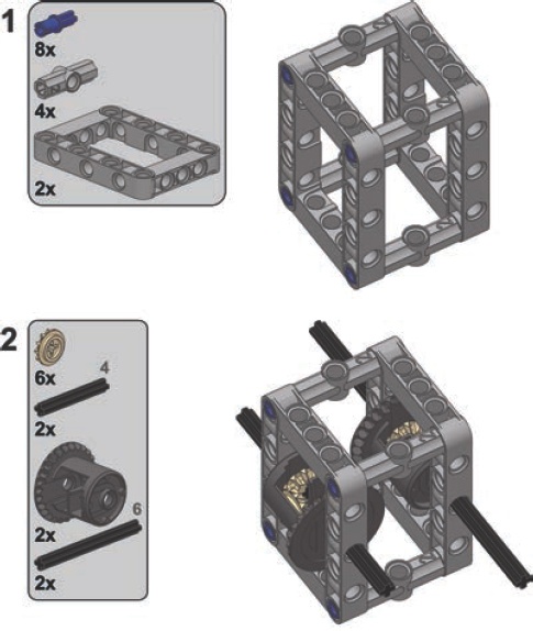
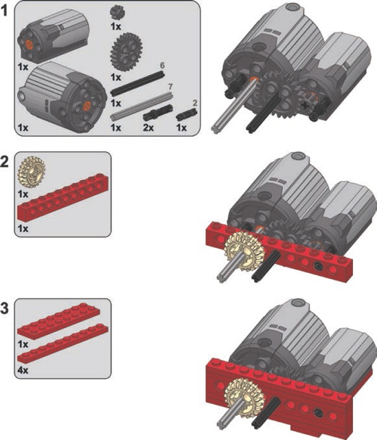
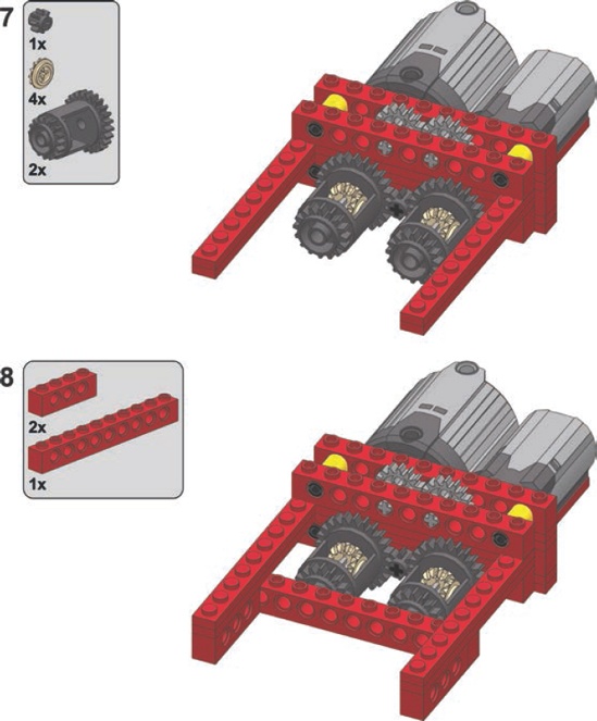
The following are instructions for building this subtractor inside a studfull structure. Note that many details can be changed as needed, including the types and number of motors and the gear ratio of the inputs and outputs. You’ll want to replace the bevel gears on the outputs with knobs if you’re building a heavy vehicle.


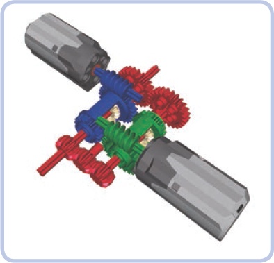
This subtractor is smaller and a little less complex than the longitudinal one. Figure 18-14 shows an example of this subtractor with two outputs (shown in red), the driving input (blue), and the turning input (green). Note that we can use the outputs coming from the other differential just as well, and it will work, but the inputs’ roles will be swapped: The turning input will become the driving input, and the driving input will become the turning input.
The transverse subtractor differs from the longitudinal version in several ways. Each motor drives a single differential, and two sets of gears connect the two differentials. One set has an even number of gears, and the other an odd number. The important thing is that both sets have a 1:1 ratio. Therefore, when using this subtractor with two different motors, it’s crucial to make sure that the stronger motor doesn’t drive the weaker one—a gear reduction at the weaker motor should prevent this.
This configuration offers more room for experimentation than the longitudinal subtractor does. For instance, we can relocate the motors if we drive the differentials with worm gears, preventing the problem of one motor driving another, as shown in Figure 18-15.
Finally, it is possible to build a fully studless variant of this subtractor using the new 28-tooth differentials (see Figure 18-16). It looks very different, but it works just the same.