The previous chapter introduced us to the principles of steering in wheeled vehicles. Now, we’ll take a look at two topics that are inextricably linked to steering axles: suspending axles and driving them. These interrelated mechanisms are frequently “separate,” yet because they affect the same final element, the wheels, they can be built only in a limited number of combinations. For example, a suspension of a given type will work only with certain steering and drive systems.
Any axle of a wheeled vehicle can be suspended, driven, and steered at the same time. An axle can, of course, do none of these things and merely hold wheels together, but since such an axle is very simple to build, this chapter will focus on axles that are at least driven. We’re going to discuss axles in four groups of increasing complexity:
Driven axles (those that receive power)
Driven and suspended axles
Steered and suspended axles
Driven, steered, and suspended axles
After going through the first group, we’ll focus on the concept of suspending wheels; we’ll learn how suspension systems work, how they are categorized, and how to choose the suspension that best suits our needs.
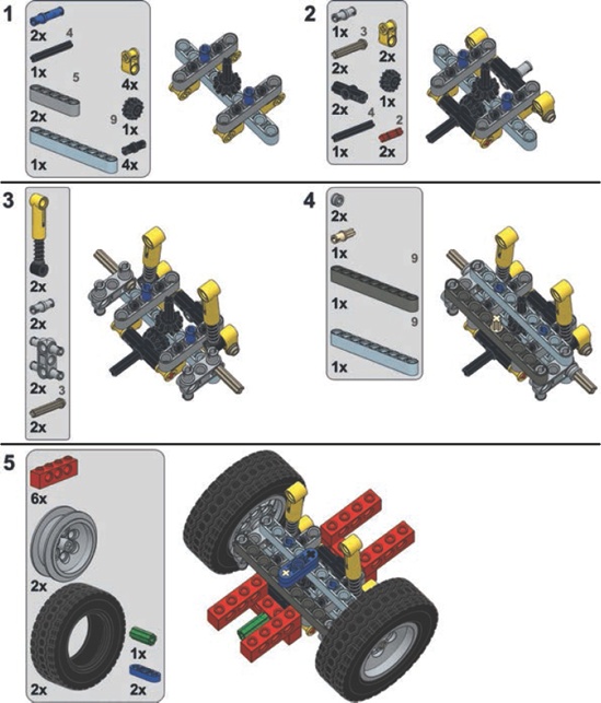
A driven axle is a mechanism that connects two wheels while transferring drive to them from the chassis. The power is usually received from a driveshaft that is longitudinal to the chassis and perpendicular to the axle. Connecting these two elements is necessary, and a pair of bevel gears is the simplest solution. But in practice, bevel gears are prone to skipping under high torque, and a driven axle is where we can expect high torque. This leaves us with two other options: a differential or a pair of knobs. A differential is less likely to skip, especially if braced inside a proper structure (shown in Figure 15-1), and knobs are extremely unlikely to skip at all thanks to their design (shown in Figure 15-2).
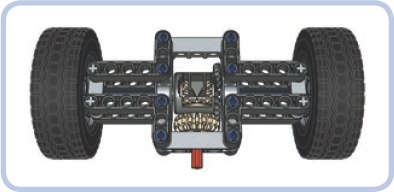
Figure 15-1. This is what a simple driven axle, also known as a live axle, can look like. The driveshaft (red) drives the 20-tooth double-bevel gear meshed with a differential case. The 5×7 studless frame braces the differential and prevents it from skipping. Note that there are two separate 7-stud-long axles connecting the differential to the wheels—axles used in this way are called halfshafts.
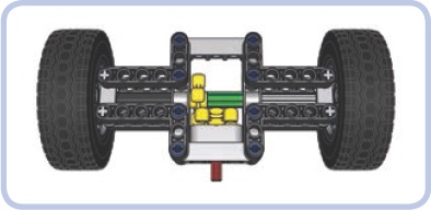
Figure 15-2. The same simple driven axle with a pair of knob wheels instead of a differential. The knob wheels are very unlikely to skip even if braced in a weak structure. Note that the two wheels’ axles are now connected with an axle joiner (green), so they work like a single axle. For more information about using differentials, their pros and cons, and even ways of creating a custom differential, see Chapter 8.
A suspension is a system of linkages that connects the chassis of the vehicle to the wheels. Its primary purpose is to keep all wheels in constant contact with the ground, thus ensuring stability and proper traction of the vehicle. The suspension can also isolate the chassis from bumps and vibrations generated by the ground—but this is actually its secondary function, and it’s not even present in all types of suspensions.
In order to maintain stability, a vehicle needs to be supported at no fewer than three points. For example, a bicycle is supported at just two points—where its wheels touch the ground—and it will fall over unless you support it at another point or drive it fast, in which case the stability comes from the gyroscopic effect of a wheel’s rotation. So a vehicle needs at least three points of support, and we’ll call these points fulcrums in our suspensions. Sometimes they are simply called points—hence the name 3-point suspension for a suspension that provides three fulcrums for a vehicle and 4-point suspension for one that provides four.
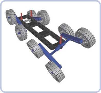
It’s important to understand that with a suspension system, the number of wheels and the number of fulcrums differ. An unsuspended axle provides two fulcrums (one at each wheel), while a suspended axle provides just one, at the point of its attachment to the vehicle. For instance, a vehicle with four wheels can have one suspended and one unsuspended axle to get three fulcrums (Figure 15-3). A six-wheeled vehicle will also have three fulcrums if all three axles are suspended (Figure 15-5).
Consider a few simple examples in Figure 15-3 to Figure 15-7 of chassis with various numbers of wheels and three (or more) fulcrums (fulcrums are marked with red arrows, chassis are black, and oscillating suspension parts are blue).
The way the wheels move in relation to each other is the first way to categorize a suspension:
A suspension is independent when one wheel on a given axle can move without affecting the other one.
A suspension is dependent when it’s impossible to move one wheel on a given axle without affecting the other one.
In dependent suspensions, when one wheel of the axle goes up, the other one goes down, and vice versa. All the simple examples here are dependent (Figure 15-3 to Figure 15-7). Also note that suspension types can vary between different axles. One vehicle can have, for example, an independent front suspension (on the front axle) and a dependent rear suspension (on the rear axle). Such a combination is actually quite popular because it allows you to build vehicles that are only as complex as necessary. In many cases, there is simply no need to use advanced suspension systems on all axles.
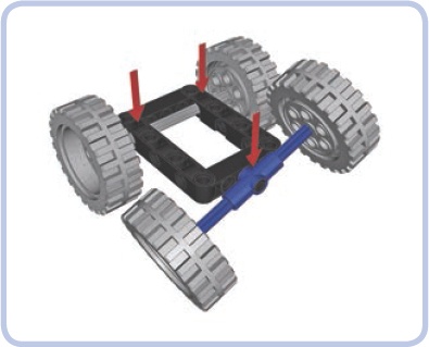

Figure 15-4. It’s possible to build chassis with just two fulcrums, like this one with two suspended axles, but the chassis will need elastic elements supporting it against the axles to prevent it from falling to the side.
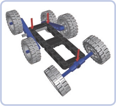

Figure 15-6. A chassis with eight wheels and four fulcrums, meaning it has a 4-point suspension. Long, multiwheeled vehicles often have more than three fulcrums.
Secondly, we can categorize suspensions by how they transfer shock from the road surface:
A suspension is sprung when the chassis is supported by elastic elements attached to the given axle so the shocks from the axle are partially absorbed.
A suspension is unsprung when the chassis is supported by the given axle directly so the shocks from the axle are fully transferred to the chassis.
The easiest way to tell a sprung suspension from an unsprung one is by trying to press the vehicle’s body down on its wheels. A sprung suspension will make the body yield, while an unsprung suspension will not. This is because a vehicle with unsprung suspension maintains constant ground clearance, which means that the middle of the chassis always stays the same distance from the ground. That makes unsprung suspension commonly used in heavy machinery, as it does not yield under heavy loads.
Of the many real-world suspension systems, we will learn to build four with LEGO pieces:
Basic independent suspension
Tatra-type suspension (a special kind of independent suspension developed and patented by the Tatra company)
Pendular suspension (a very simple, dependent suspension based on a single axle’s rotation)
Floating axle (an axle with no rigid connections to the chassis whatsoever)
We will now discuss these suspension types using simple models of each. After that, we’ll look at actual suspension designs.

The chassis is black, the suspension arms are yellow, the steering arms (not steered in this case) are blue, and the spindles are green. As you see, each steering arm is suspended on four parallel levers that allow it to move up or down relative to the chassis while keeping the wheel in a vertical position. Consider the examples in Figure 15-8 and Figure 15-9.
One element is missing from these images—the suspension arms need to be actually suspended. In other words, the chassis needs some elastic elements to support it against the suspension arms, or else the entire suspension will collapse. Shock absorbers are well suited and popular in this role (see Figure 15-10). Figure 15-11 provides an example of a model that uses independent suspension.
Advantages: Best suspension type in terms of stability and traction; the orientation of the wheels is maintained at all times
Disadvantages: Large width; relatively fragile construction
Note that it’s possible to use the same elastic elements for the suspension arms for both wheels, but this will make the suspension dependent—causing one wheel to go up while the other one goes down (see Figure 15-12).

Figure 15-8. Independent suspension with one wheel on an obstacle. Note that the position of the other wheel is unaffected, as it should be with an independent suspension.
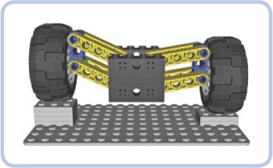
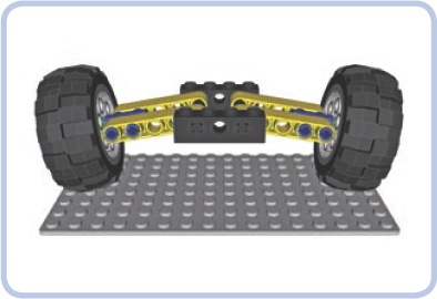
Figure 15-9. Independent suspension with both wheels on obstacles. Both wheels negotiate obstacles independently; hence the name of the suspension type.

Figure 15-10. Independent suspension with four shock absorbers supporting the chassis against the suspension arms


The Tatra-type suspension, also known as a swing-arm suspension, was developed and patented by the Tatra company, which uses it almost exclusively. The Tatra-type suspension is a simpler variant of the independent suspension that uses only two levers per wheel as suspension and keeps the spindles perpendicular to the suspension arms at all times. This means that the orientation of the wheels changes as they negotiate obstacles. By default, the wheels are tilted, as shown in Figure 15-13, a unique feature for this suspension type.
Figure 15-13. The default position of the Tatra-type suspension offers extra ground clearance. This “bowed” look can be mistaken for damage or warping.
Other than the tilting of the wheels, the Tatra suspension, shown in action in Figure 15-14, shares all the qualities and properties of a regular independent suspension. It is valued for the robustness coming from its simplicity, and it performs very well on rough terrain (Tatra off-road trucks are nothing short of legendary); its only downsides are inferior sideways stability and poor tire wear. Such a suspension is viable only for heavy off-road vehicles.
Advantages: Simpler, more robust than a typical independent suspension
Disadvantages: Slightly inferior traction because of the wheels’ changing orientation; inferior sideways stability


A pendular suspension is the simplest and the most robust kind of suspension: It allows the axle to swing back and forth on a single point just like a pendulum. As it’s only one solid element, it can be very narrow and built with just a few pieces. Figure 15-15 shows a pendular suspension in action.

Figure 15-15. A pendular suspension negotiating an obstacle with one wheel. Note that the chassis, which is connected to the axle by the axle going through its center, is raised by 50 percent. This is generally bad for stability and for the driver’s comfort.
On the downside, pendular suspension systems take a lot of space in the chassis, requiring the model to have a large gap in order for the suspension to fit. The pendular suspension system can’t be sprung, but it often requires shock absorbers (see Figure 15-16) or other elastic elements to keep it stable—unless you arrange the suspended axles of your vehicle so as to provide three or more fulcrums. The longitudinal axle that goes through it is also the only way to transfer the drive to the suspension from the chassis. So the longitudinal axle is used as the driveshaft, which means that this suspension is mounted on the driveshaft and presses on it, creating extra friction.
Advantages: Simplest and most robust suspension type; can be very narrow
Disadvantages: Unsprung; takes a lot of space in the chassis; adds extra friction on the drivetrain (see pendular suspension with turntables in pendular suspension with turntables for a means of mitigating this effect)
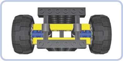
Figure 15-16. A pendular suspension stabilized with a pair of shock absorbers. Note that the shock absorbers work against each other and need to be half compressed when the suspension is level. When one wheel goes up, the absorber close to it is compressed more, and the other one is compressed less.

A floating axle suspension (or live axle) is a sprung variant of the pendular suspension. It’s a single solid element that has no rigid connections to the chassis whatsoever; instead, it is connected to it by a number of links that form a linkage allowing it to move up and down and tilt to the sides. It can be just as narrow and robust as a regular pendular suspension, and it doesn’t press on the driveshaft. However, it takes an extreme amount of space in the chassis because of the linkage that comes between it and the chassis.
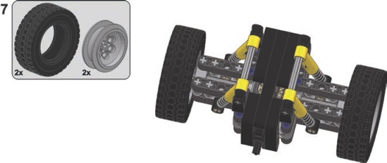
Floating axles can be extremely complex. The variant we will focus on is a simple one (see Figure 15-17): It uses four links and two independent suspension arms above the actual axle that need to be supported by some elastic elements. It also uses a driveshaft with a single universal joint on it to keep the axle aligned with the chassis.
Advantages: Combines all the advantages of pendular suspension with being sprung and usually more stable
Disadvantages: Takes a lot of space in the chassis
Choosing the best type of suspension for the job is always a little tricky, but your decision can be made easier by considering what is used in real vehicles. For example, luxury cars usually have full independent suspension to improve passengers’ comfort, while construction vehicles—such as front-end loaders, for instance—usually have pendular suspension because the heavy loads they are handling would affect a sprung suspension too much.

Axles that are driven and suspended at the same time are relatively easy to build, and they’re important as the vast majority of vehicles has at least one.
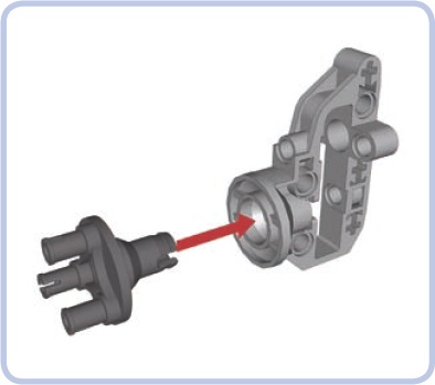
As explained earlier, the pendular suspension has the disadvantage of being attached to the chassis by the driveshaft, which is subject to stress generated by the vehicle’s weight. This single point of stress creates additional friction; however, this problem can be prevented almost completely by using a Technic turntable to attach the suspension to the chassis (see Figure 15-18), as an alternative to using ball joints. The turntable then supports the weight of the vehicle, while the driveshaft can go through the middle of the turntable nearly unburdened.

Figure 15-18. The newer type of Technic turntable is used to attach the suspension (the light grey frame) to the chassis (the black L-shaped beams). A turntable is a very rigid structure capable of supporting huge loads while adding minimum friction to the driveshaft (red) that goes through it.
Note that the large diameter of the turntable is bad for ground clearance, so it’s a good idea to use this design in concert with portal axles. Also note that the hole in the turntable is large enough to install a differential case in it, which can be used to transfer both drive and steering through a single turntable (see Figure 15-19).
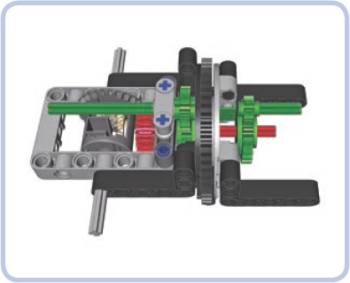
Figure 15-19. As an empty differential case rotates freely on an axle, it can be used to transfer steering over the driveshaft. Here, red pieces are acting as a driveshaft and green pieces are acting as a steering shaft without interfering with each other. Note that the steering shaft is slightly affected when the suspension tilts and the turntable rotates. Still, it’s a useful solution when the driveshaft and steering shaft need to be connected to the suspension from the same side.
This is a simple, robust, and compact suspension kept stable by four shock absorbers. Keep in mind that absorbers of various length and hardness can be used.


Portal axles are axles with gear hubs on the wheels that increase both ground clearance and the gear reduction of the drivetrain, as Figure 15-20 shows. Practically any axle, including a steered one, can have gear hubs and become a portal axle at the cost of increased width. The most popular are hubs with a 24-tooth and 8-tooth gear combination, providing a 3:1 gear reduction. The 3:1 gear reduction means not only that torque on the wheels is increased three times but also that other parts of the drivetrain handle only a third of the overall load. This is very useful for steered axles because it allows us to use universal joints, which could otherwise be damaged by the load.

There are a number of ways to build narrow, strong gear hubs. The easiest one, however, involves a ready-made LEGO gear hub housing: a #92908 piece, into which a #92909 is inserted to support the wheel (see Figure 15-21). We will refer to this very convenient combination as a LEGO hub. Figure 15-22 shows a model that makes use of LEGO hubs.
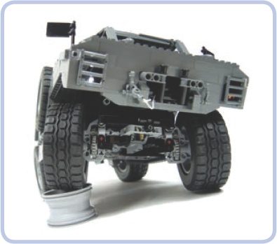


This is a simple, robust suspension without a differential, well suited for rough terrain. Remember to set up the shock absorbers so that the wheels are tilted slightly downward when the suspension is unloaded.
Note
It’s possible to convert this design to use a portal axle, but it’s not recommended with this suspension as doing so would decrease its sideways stability.


Here’s a look at some building instructions for axles that are suspended but can also be steered. These are commonly used for the front axle of real-wheel-drive cars.


Here are building instructions for the most complicated category of axles.
This axle is just slightly more complicated than the version without steering.
Note
There is an older version of this suspension using different (older) pieces in the 8880 LEGO set.
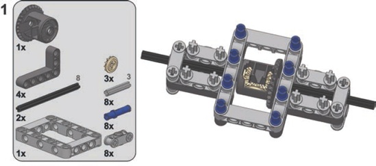
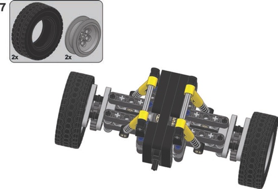
This is a complex and extremely robust suspension designed for very rough terrain. It includes knob gears instead of a differential, and it consists mostly of basic studless pieces.