
This chapter presents devices that make creative use of pneumatic systems: motorized compressors, remote controlled valves, and pneumatic engines. All these devices take advantage of the fact that the pneumatic system has been designed to be customizable, and there’s almost no limit to potential modifications.
In this chapter, we’ll start by discussing the most basic and versatile devices and then move on to more sophisticated and specialized ones.
A compressor is a stand-alone mechanism that provides a continuous supply of pressurized air—for example, the massive air compressor you can find at the gas station (for reinflating tires) or the portable model you might use to inflate an air mattress. The most practical and popular method of building a Technic compressor is by driving small LEGO pumps with a motor. This method allows us to control a compressor remotely, and it ensures that the compressor works at a constant rate, making the cylinders in a pneumatic system move smoothly.
It’s convenient to keep the motor attached directly to a compressor. This allows us to place the whole mechanism practically anywhere in our construction, as we are not bound by driveshafts, gears, or any other rigid elements. Our only limitation is finding a home for the electric wire and pneumatic hose.
There is one issue worth keeping in mind when building a motorized compressor: its ripple. LEGO pumps work in a cycle: They are retracted, pumping air into their outlets, and then extended, taking air from outside. In other words, they don’t provide air constantly but only during exactly half of the cycle. This cycle has two consequences that become more significant as the number of pumps working simultaneously increases: fluctuating air flow and vibrations, which result from the pumps’ rods being repeatedly pushed back and forth.
Some builders are fond of building monstrous compressors with eight or more pumps driven by the RC motor (shown in Figure 10-1). This is not always the best solution, as RC motors are large, loud, and power consuming. Another solution is to divide pumps into groups that work alternately. For example, instead of four pumps working as one, we can use two pumps that are retracted while the other two are extended. Ideally, we should have multiple pumps that are fully out of phase because this limits both the load on the compressor’s motor and the vibrations the compressor creates. Supporting the pumps’ ends as rigidly as possible also reduces vibrations.

Figure 10-1. An eight-pump compressor driven by the RC motor. This design is a real monstrosity in the world of LEGO compressors.
You might ask why we would want to use so many pumps in the first place. It’s because a single pump has a very small capacity and is, therefore, not very powerful, taking quite a while to fill just a single large pneumatic cylinder. How fast your pneumatic system operates depends on the volume of pressurized air delivered to it, so using many pumps is a natural solution. The rule of thumb is that for a pneumatic system in which one or two large cylinders are working at the same time, it takes at least two pumps for a PF Medium motor to provide air pressure at reasonable rate.
Note
All of the compressor designs in this chapter are intended for pumps that are 5.5 studs long when extended, not for the newer 6-stud-long version. This longer version is found only in a single set and is therefore quite rare.
Figure 10-2 through Figure 10-6 show various compressor designs that drive more than one pump.
The rocking compressor, shown in Figure 10-6, can hold from 2 to 18 pumps, depending on the length of its axles. It moves the pumps in a reciprocating motion, rather than the rotary motion used in other compressors, which results in a more compact build. Moreover, it has a gearing with four possible gear combinations (see Figure 10-7).
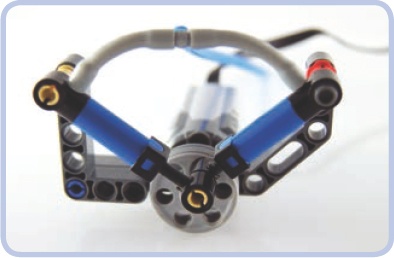
Figure 10-2. A compressor with two pumps that work alternately, both attached to two wedge belt wheels. The design is small, but it’s difficult to add more pumps to it. In this compressor, the pumps are 90 degrees out of phase rather than 180 degrees, so the pressure is still “uneven.” in other words, one pump is not fully extended while the other is fully compressed.

Figure 10-3. A compressor that can hold two or four pumps while making use of two 36-tooth gears. The orientation of the gears relative to each other is maintained by two 12-tooth gears on a separate axle, which also transfers drive between them. It’s possible to connect two or more such compressors side by side to increase the number of pumps.

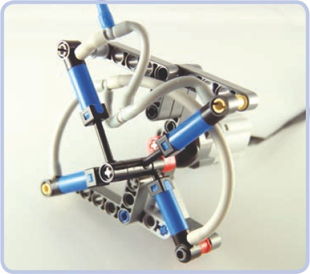
Figure 10-5. You can even split pumps in a compressor into four groups at various points of the working cycle. But such compressors are significantly more complex while working only a little more smoothly.


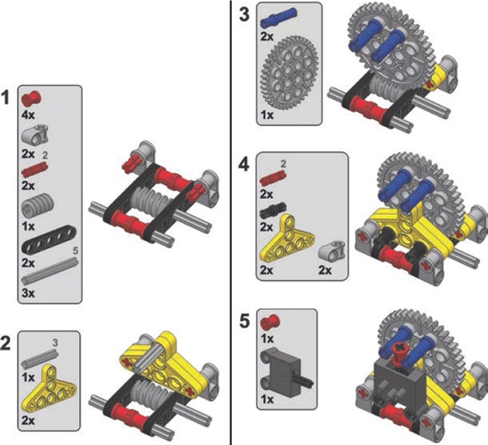
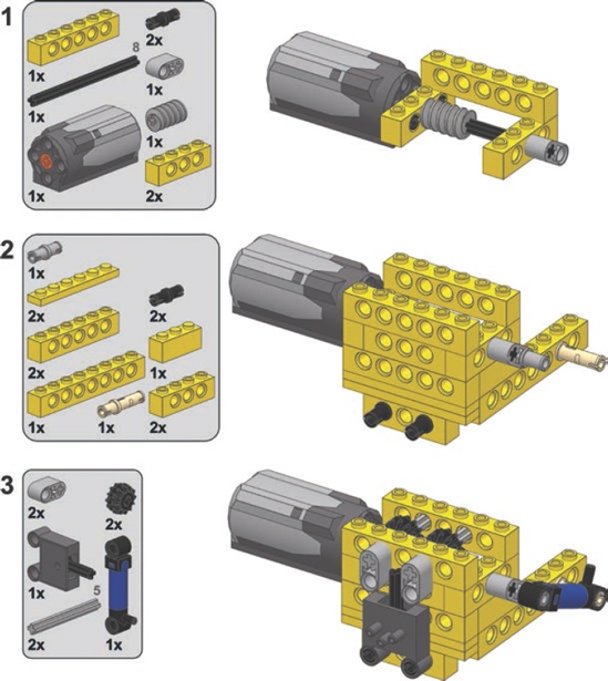
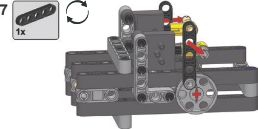
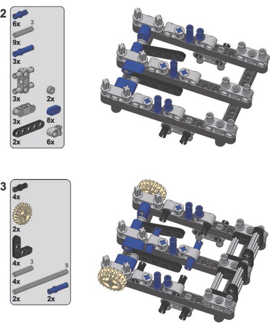
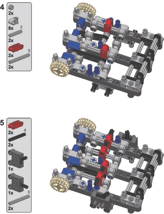
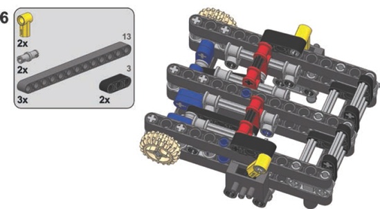
Here’s a look at the complete building instructions for a simple design. The blue axles limit the number of pumps, but making the axles 1 stud longer adds space for two more pumps. For clarity, the instructions show the compressor without pumps, but the pumps should be mounted on the blue axles.

The purpose of motorizing a pneumatic valve is simple: remote control. A valve can be connected to a motor in a simple way, preferably with the use of a 24-tooth gear with a clutch, which prevents the motor from stalling (see Figure 10-8). Once the 24-tooth gear can no longer drive the valve, the grey circle inside the gear begins to rotate instead, which prevents damage to the motor or to the gearing.
Polish builder Maciej “dmac” Szymański discovered that if we use this exact combination of motor and gears with a regular 24-tooth gear (without a clutch), we’ll get a return-to-center motorized valve—that is, a valve that returns to central position the moment the motor stops, thereby shutting down the valve (see Figure 10-9).

Figure 10-8. A simple way to motorize a pneumatic valve is to use a gear with a clutch for the motor’s safety.
But precision is often crucial when switching pneumatic valves. The designs above lack precision, while the design shown in Figure 10-10 offers plenty of fine-grained control. This is useful for retracting heavily loaded cylinders, when the valve has to be opened little by little to prevent cylinders from yielding to the load.

Figure 10-9. With a regular 24-tooth gear instead of the clutch gear, we get a return-to-center valve.
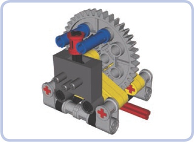
Figure 10-10. This high-precision valve-switching mechanism makes use of a worm gear and a 40-tooth gear to ensure accuracy. The red bush on the valve’s lever improves it further by reducing backlash. Note that there is no safety clutch in this assembly; because the mechanism multiplies the motor’s torque by a factor of 40, there is a chance that some pieces may be damaged if the motor doesn’t stop at the right moment. To lessen this risk, a clutch can be added between the valve and the motor.
An autovalve combines the functions of a motorized valve with those of a compressor. It makes use of the compressor’s ability to function regardless of the input’s direction of rotation—we’ll use the motor’s direction of rotation to control the valve itself. After switching, the motor can continue to drive the compressor as long as is needed.
The autovalve’s working principle is based on a so-called sliding worm gear, as shown in Figure 10-11. The motor drives the compressor through an axle on which a worm gear is located. The worm gear drives one of two identical short axles with a 12-tooth gear and a short beam (shown in green). The beams act as pushing elements: Each of them can push the valve’s lever in one direction and then continue rotating freely. But when driven in the opposite direction, the beam locks against the lever, stopping the respective axle and making the worm gear slide away from it. The worm gear slides until it meshes with the other axle’s gear, at which point it starts to drive it and the other pusher located on it, effectively switching the valve.
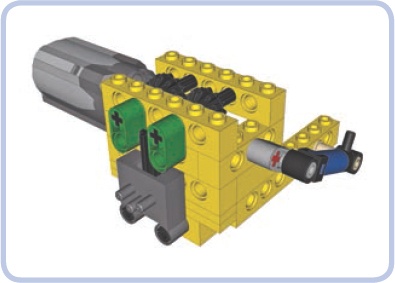
Figure 10-11. An autovalve uses a sliding worm gear to control a compressor and a pneumatic valve with just one motor.
The disadvantages of the autovalve include a long switching time, which can be remedied by driving the input faster, and the limit of one valve and one compressor per motor. Still, the compressor can be connected to any pneumatic system, with more valves controlled separately (see Figure 10-12).
To see an autovalve in action, visit http://www.youtube.com/watch?v=OsDJ4iTs-P8.

Having a motorized compressor in your pneumatic system doesn’t necessarily solve your pressure problems. Complex pneumatic systems with many cylinders working in turns can require large amounts of pressurized air in the system at one moment and no air moments later. While the amount of air pressure that goes into a system can be managed by building a compressor fast and/or large enough, constantly turning it on and off can be an onerous task.
The solution to this problem is a pressure switch, also known as a pressure limiter. We can build one using a PF switch, a small pneumatic cylinder, and a rubber band.
How does a pressure switch work? Take a look at Figure 10-13, which shows how the switch connects the compressor motor to the power supply. The cylinder’s lower port is connected to the pneumatic system, while the upper one is left open. A rubber band is put over the cylinder, keeping it retracted. If the pressure in the pneumatic system is high enough, the cylinder will overcome the rubber band and extend. If the pressure drops, it will yield to the band and retract. This means that if we connect the cylinder to the PF switch, the switch can effectively control the compressor’s motor, turning it on automatically when pressure is low and then turning it off when it’s high enough. Such a mechanism is best used with an airtank, filling it automatically when necessary.

Figure 10-13. A close-up view of a pressure switch. The switch usually needs adjusting to activate at the desired pressure threshold. It can be fine-tuned by adjusting the rubber band’s strength, the angle of the cylinder relative to the lever, and the length of the lever. It is also possible to use old 9V switches, which offer less resistance, or to use multiple cylinders. Large cylinders can be used as well, although their large capacity makes them less sensitive and therefore less useful in system that must react to small changes in air pressure.
The pressure switch works best when close to the airtank, which, in turn, should be close to the compressor, as shown in Figure 10-14. Some builders create complete modules with the motorized compressor, airtank, and pressure switch all put together. I prefer to take advantage of the elastic elements—that is, the wires and hoses—to be able to adjust the location of these elements more freely. A singular module has fixed dimensions, while separate elements connected only by wires and hoses can be fitted into limited space in different ways, allowing for less massive and more creative housings.

Figure 10-14. The general scheme of the pressure switch and its connections to other components of the pneumatic system. Black lines mark electric wires, blue lines mark mechanical connections, and green lines mark pneumatic hoses.
A properly built and adjusted pressure switch leaves you with only pneumatic valves to take care of; the compressor works automatically, and the pressure in the airtank is maintained at all times. Note that there is no particular place where the switch-airtank-compressor combination should be connected to the rest of the pneumatic system. Such a connection can be placed between the compressor and airtank, between the airtank and pressure switch, after the airtank (as shown in Figure 10-13), or after the pressure switch—it will work just the same regardless of placement. You can also connect a LEGO manometer to observe the relationship between air pressure and the functioning of the switch.
The functioning of pneumatic cylinders is somewhat similar to that of the pistons in an internal combustion engine, allowing us to build a compressed air engine with cylinders driving the crankshaft. Such an engine, sometimes called a LEGO pneumatic engine (LPE), is powered by pressurized air delivered to the cylinders. Pneumatic engines are advantageous in terms of their performance, resemblance to combustion engines, and sound, which is quite loud and carlike compared to that of electric motors. What makes these engines appealing to many builders is their complexity, which creates almost endless possibilities for improvements. While the complexity of these engines may be appealing, they’re also quite a challenge to build. Disadvantages of pneumatic engines include their size and their need to be constantly connected to a compressor. Moreover, pneumatic engines work only in one direction, and they get warm from the friction of many moving parts and from air being compressed inside the cylinders.
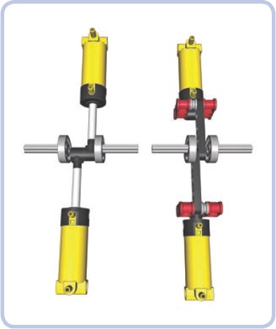
The working principle of a pneumatic engine is simple: A cylinder is connected to a shaft with a cam so that extending it rotates the shaft by a half rotation and retracting it rotates the shaft by another half rotation (see Figure 10-15 and Figure 10-16). The same shaft uses another cam connected to a valve to switch the cylinder between extending and retracting continuously, thus creating a complete working cycle. The cycle, therefore, involves both cylinder and valve and goes as follows: Cylinder extends to maximum, valve is switched, cylinder retracts to maximum, valve is switched.
The problem with the cycle is that both cylinder and valve have dead spots, or points of the cycle at which they can stop, as shown in Figure 10-17. For a cylinder, it’s the point when it’s extended or retracted to maximum, and for a valve, it’s the point when it goes through neutral position and no air comes through it. If we make an engine with just one cylinder and one valve, these dead spots will overlap and effectively stop the engine after it makes just half a rotation. This can be prevented by using a heavy flywheel and a modified valve.
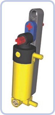
Figure 10-15. A simple way to connect the cylinder to a shaft is to use a cam made of a short beam. However, a cylinder can extend by 4 studs, but here it’s allowed to extend by only 3.

Figure 10-16. To make the cylinder extend fully, we need its tip to be mounted 1.5 studs away from the shaft. A piece called a Technic cam allows this.

Figure 10-17. A simple cylinder and valve combination with two cranks: one made of Technic cams, converting the cylinder’s motion into the crankshaft’s rotation, and another made of a wedge-belt wheel, using the crankshaft’s rotation to switch the valve back and forth. Note that both cylinder and valve are in dead spots here.
Modifying LEGO pieces is actually quite common among advanced LPE builders. The best pneumatic engines from these builders can far outperform any LEGO electric motor in terms of both speed and torque, but that performance comes at a cost. In such engines, cylinders’ ports are often drilled to increase throughput; the valves’ internal structure is cut to reduce their switching resistance; and many moving parts, such as cylinders and camshafts, are lubricated. Industrial tubing with clamps replaces LEGO hoses and is sometimes glued to the ports. Finally, these engines are powered with non-LEGO compressors, such as electric compressors for car tires. LEGO pneumatic pieces were simply not designed to move quickly, and there is a lot of friction involved in the many moving pieces of a pneumatic engine, which justifies modifications for some builders.
Getting back to our single-cylinder engine, a modified valve and a flywheel can make it work: The flywheel will provide the momentum necessary to get the engine through dead spots, while the valve will offer minimum resistance and thus minimum risk of getting stuck in a dead spot (see Figure 10-18). Such an engine needs to be started by spinning the flywheel manually, but it will keep running for as long as it receives sufficiently high air pressure.
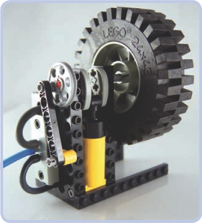
Figure 10-18. This is the engine from Figure 10-17 with a flywheel added to keep it running through overlapping dead spots. Starting such an engine is a little finicky, but it works fine once it gets going.
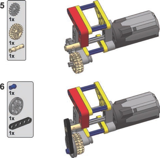
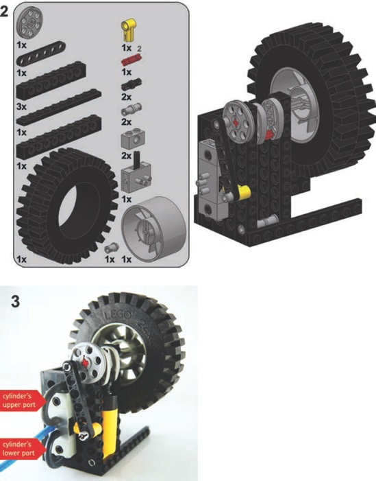
Here are the building instructions for the engine shown in Figure 10-18. Like every set of engine instructions in this chapter, these instructions have both the cylinder and hoses removed for clarity. In this BI, a photo shows the cylinder’s position and a connection scheme for the hoses. Remember that engines like this work best with a large volume of continuous air pressure, and they are difficult to drive with a LEGO compressor.

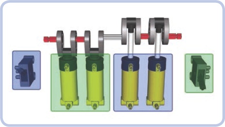
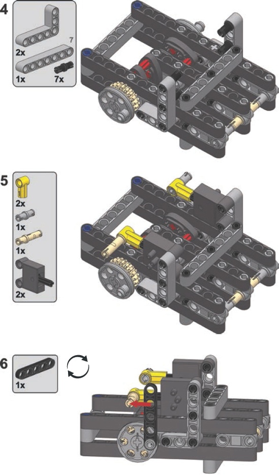
Engines with two, four, six, or more cylinders can be built as follows: The cylinders are split in two groups, each group connected to one valve so that there are two valves in the engine for any number of cylinders. At any given time, one group of cylinders is retracting while the other is extending. These groups should be mixed so that no two cylinders of the same group are next to each other. All the cylinders are connected to a common camshaft, but with cams rotated 90 degrees relative to the adjacent ones (see Figure 10-19). This reduces the overlap of the cylinders’ dead spots. Finally, each valve is connected to the end of the camshaft closest to the group of cylinders connected to the other valve, as shown in Figure 10-20. This arrangement ensures that we don’t overlap dead spots between a valve and the cylinders connected to it.

Figure 10-19. A two-cylinder engine built in accordance with the rules above. The colored dots show which ports are connected. Note the position of the cams. The engine can start all by itself and runs relatively smoothly. The tan gear can transfer drive from the engine. More cylinders can be added to the engine, and it reaches optimum smoothness with four cylinders, each with a cam rotated 90 degrees relative to the next one.

In general, the more cylinders we add, the smoother the engine will run. The engine reaches optimum performance when we use at least four cylinders, each with its cam rotated 90 degrees relative to the adjacent ones (see Figure 10-21). On the other hand, adding more cylinders will result in a greater combined engine capacity, which will in turn increase fuel consumption. Note that the efficiency of LEGO compressors is poor compared to the capacity of such an engine. Note also that the engine’s efficiency can’t be improved by using airtanks because the engine needs a constant supply of equally pressurized air and airtanks provide only a single, short blast of very highly pressurized air. You can, of course, build an engine with a separate valve for each cylinder. Some builders do that for smoother operation, but it drastically increases the overall complexity of the engine.
One last issue is that cams are quite fragile when subjected directly to the cylinder’s power. This problem can be remedied by using sliders—that is, elements that move together with the tip of the cylinder and thereby transfer movement to the cams (see Figure 10-22). Sliders keep a cylinder’s tip moving in a straight line, and this creates a more favorable distribution of force, leaving the cams less stressed. The use of sliders is also more efficient because the cylinder’s power is not wasted by tilting it sideways; instead, all of the power is transferred to the cam. Additionally, with cylinders maintaining the same position, it’s possible to pack them more tightly. Sliders are very popular in complex engines—especially in those in the V system—as they allow a sturdier overall construction.
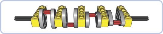
Figure 10-21. The “optimum crankshaft,” with four cams, each rotated 90 degrees relative to the next one, provides the smoothest operation possible for a pneumatic engine.
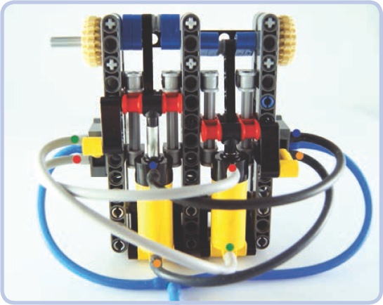
Figure 10-22. A two-cylinder engine with sliders. The colored dots show which ports are connected. The sliders are built around the red pieces, each moving along two light grey axles. They keep the cylinders’ motion in a straight line and then transfer the motion to the cams (blue). Note that the extension of the cylinders is limited to 3 studs rather than 4, but thanks to this limitation, the sliders can also be used to control the valves.

Engines in the V configuration are engines with cylinders aligned in two planes that form the shape of a letter V when viewed along the axis of their common camshaft. These engines can be built in two ways, both of which require building two identical modules with cylinders lined up and connecting them at a right angle. The first way is to build them with two separate crankshafts, each for one module, and to then use gears with a single central shaft to connect the modules. The second way is to use a single common crankshaft for both modules and to then connect two cylinders to each single crank pin. Since we want to keep the modules aligned (as they are in real engines), it’s easier to use half-stud-thick beams to connect sliders to the cams rather than use 1-stud-thick cylinder tips (see Figure 10-23).
The possibilities with pneumatic engines are vast and include engines in W, boxer, and even radial systems. You can find many ingenious variants shown in detail by visiting Dr. Dude’s YouTube channel: http://www.youtube.com/user/DrDudeNL/. Dr. Dude, a Dutch builder, has been a fan of the LEGO Technic set—and of big Technic cars in particular—for over 30 years.
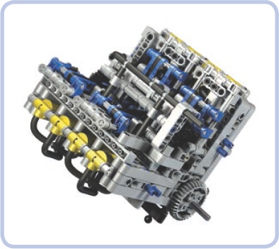
Many LEGO builders produce impressive pneumatic engines, but one of them is the unquestionable master in this field: Alex “Nicjasno” Zorko. Alex builds big and heavy models of sports cars and found LEGO motors too weak to drive them. He has developed incredibly advanced motors, including “simple” inline engines, a V6 that operates at speeds well above 2000 RPM, and a V8 strong enough to make even a very heavy model drift (shown in Figure 10-24). Alex shows his models at http://nicjasno.com/ and sells his engines at http://lpepower.com/.
While LEGO Technic creations don’t mix well with fluids, it is possible to build a pneumatic pump that will work with water while ensuring that no sensitive pieces come into physical contact with liquid. This pump uses pressurized air to push water, making it fairly safe and simple to use in, for example, a LEGO fire engine model.
To create a water pressure pump, we need an airtight container that will initially be filled with water and will then have pressurized air delivered to it. Using LEGO pieces for such a container may not be the best idea; a small bottle with a metal or plastic cap is a better alternative.
The working idea of this pressure pump is that by delivering air into a closed, water-filled container, we can force the water out. The container therefore needs an entry for the air and an exit for the water. The entry can be anywhere in the container; the exit should be at the bottom to stay in contact with water as long as possible.
We can adapt our bottle by making two holes in the cap and putting two hoses through them, as shown in Figure 10-25. One hose (dark grey) will deliver air and can end just below the cap or go deeper into the bottle—it doesn’t matter. The other hose (blue) will be the water’s way out, and it should reach all the way to the bottom. It’s a good idea to make the other hose stiff so that it doesn’t float in the water; a rigid LEGO hose or a regular drinking straw can be used. The hardest part is making the cap airtight with hoses going through it. You can achieve this by using modeling clay, masking sol, or molten wax from a candle.
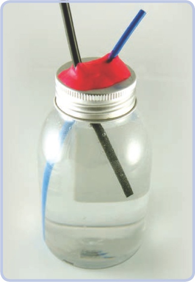
Figure 10-25. A small plastic bottle with a metal cap makes for a very good container. The dark grey elastic hose delivers air, while the blue rigid one lets the water out (note that it can be extended by putting another elastic hose on its end). The cap was punctured in two places to let the hoses through and then sealed with modeling clay (pink).
Now you can connect the first hose to any compressor, and the water will spurt from the other one. Note that water is much less compressive than air, so it will take very high air pressure to make water really spurt. You can make your pump more effective by delivering air to it faster and by making the exit hose narrow. You can also use an airtank full of pressurized air and connect it to the first hose through a pneumatic valve; opening the valve will empty it into the bottle in an instant.
Just make sure the water doesn’t come out anywhere near the electric components of your construction!