
Now that you have your ideal model in mind and you’ve learned how to scale all dimensions of the object accurately, it’s time to start building. This is where you start putting your plans to the test, figuring out all those little forgotten details.
While many builders are tempted to build big, and while size can indeed be an impressive feature of any LEGO construction, Technic models don’t necessarily benefit from large size. Going big creates a number of problems that increase rapidly with size, including significant stress on many sensitive pieces and problems with the mobility, balance, and structural integrity of a model. One of my models was tall and very heavy, with a tracked chassis that I thought was strongly reinforced. When it reached a weight of 7 kg, the chassis was bending so much that it couldn’t keep the body stable while moving. Even sturdy Technic bricks become quite elastic if the load exerted on them is large enough.
A good rule of thumb, especially for less experienced builders, is to build as big as needed rather than as big as possible. In other words, you should aim to make your model as small as possible. To estimate how small it can be, you have to consider the largest single-piece elements it’s going to house, such as battery boxes, motors, and IR receivers. Tracked vehicles are a good example here—their box-shaped hulls need to be wide enough for two motors set either side by side (see Figure 21-1) or back to back (see Figure 21-2). If a narrower hull is used, wider elements—such as the power supply—must be set above the tracks.
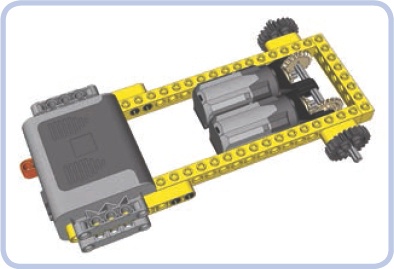
Figure 21-1. An 8-stud-wide hull with a 6-stud-wide internal space, large enough to house two PF Medium motors side by side, one driving the left sprocket wheel and the other driving the right sprocket wheel. A Power Functions battery box can also be housed inside if you make holes for it in the sides of the hull. The protruding parts of the battery box can be concealed inside the tracks.
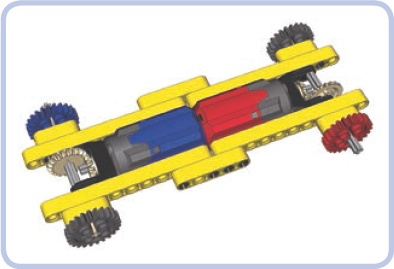
Figure 21-2. A 5-stud-wide hull with a 3-stud-wide internal space, large enough to house two PF Medium motors back to back. As the red and blue colors indicate, one motor drives the front right sprocket wheel, while the other drives the rear left one. The remaining two sprockets are idlers. Wider elements, such as the power supply, must be moved above the tracks where the hull is wider.
There are many creative ways in which you can fit large elements into a small model. For example, when building an excavator, you can try to fit small motors, such as PF Mediums, in the arm if it’s massive enough, or you can install them between the tracks if the ground clearance allows (see Figure 21-3). You can also try to disguise the motors. One of the trucks I built could house motors only in its cargo hold. When I covered the motors up with plates, it looked like the cargo hold was gone. When I left the motors exposed, they looked like a load carried by the truck. Try to experiment—the more solutions you attempt, the closer you are to finding the best one.
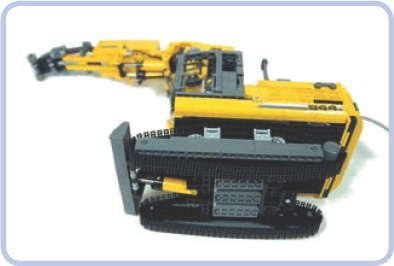
Figure 21-3. My model of the Liebherr R944C tunneling excavator housed more motors in the chassis than it did in the superstructure, at the cost of nearly zero ground clearance. With more space available inside the superstructure, I was able to take better care of its aesthetics.
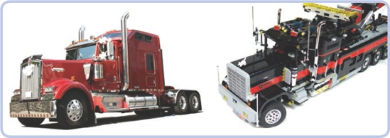
The complexity of a model is another issue. Very complex models are always impressive, but they are also very difficult to build. My most complex model so far, the tow truck shown in Figure 21-4, housed 17 motors and nearly 19 m of electrical wires. To make it possible, I had to provide special isolated ducts inside its body specifically for wires. It’s always a good idea to keep in mind that complexity should be a result, not a goal in itself.
Regardless of how confident you feel, it’s good to gather some experience building reasonably small and simple models before trying something big and complex. With enough experience, you will notice that big and complex vehicles are often basically a sum of what you’ve done with smaller ones. For example, you might combine one model’s suspension with another’s gearbox. Bigger and more complex projects feel more rewarding when completed, but they are also more likely to fail.
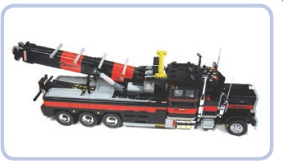
Figure 21-4. My tow truck model housed 17 motors and nearly 19 meters of electrical wires, requiring ducts inside the body. Note that the mechanical and electrical parts are all enclosed within the body, with a few minor exceptions, such as the PF Medium motor, which is partially visible by the boom’s winch, and the gears of the steering system, which are visible next to the front mudguard.
Most LEGO wheels have different proportions than wheels used in real vehicles—they are significantly wider. While this may not be a big problem for many types of models, it can become an issue for vehicles that have more than two wheels on a single axle, trucks being the primary example.
The vast majority of trucks use double wheels on all rear axles. Models with single wheels, no matter how wide, just don’t look accurate. For example, the 62.4×20 wheels, a favorite of LEGO truck builders, are 5 studs wide when doubled. That means that an axle with four wheels of this type needs a 10-stud-wide space just for the wheels alone. As Figure 21-5 shows, such an axle can’t possibly get narrower than 16 studs, unless you abandon the differential.
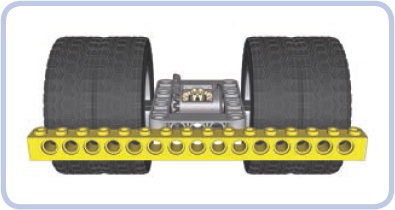
Figure 21-5. It’s possible to build a driven axle with four 62.4×20 wheels that fits within a 16-stud width—but just barely
As you can see in Figure 21-6, the width of the driven axle is one of the major factors affecting the size of the model. And things get even more difficult when there is a suspension system, especially an independent suspension that takes plenty of space between the chassis and the wheels.
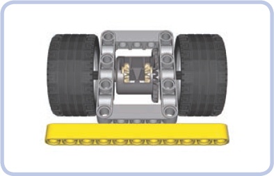
Figure 21-6. Small wheels are often wide, so it’s difficult to use more than two per axle. These wheels, often used in small trucks, are 3 studs wide with just a 5.5-stud diameter. An axle with two of these is 11 studs wide, while an axle with four would be 17 studs wide.
Another important issue is the profile of the tire, which can be rectangular (as with regular tires) or round (as with so-called balloon tires). Figure 21-7 shows the same wheel with a regular and a balloon tire. The balloon tire is bigger, with a slightly larger diameter, but its side surface is smaller because of its profile. Balloon tires look good fully exposed, but when viewed from the side, especially when enclosed within the body, they can actually appear smaller than regular tires, as Figure 21-8 demonstrates.
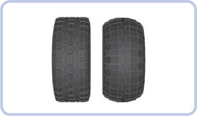
Figure 21-7. The so-called Technic Racing wheel with a regular tire (left) and a balloon tire (right). The tires are very similar in size, but the balloon variant is softer, has deeper tread, and usually works better on rough terrain.
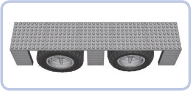
Figure 21-8. The Technic Racing wheel with a regular tire (left) and a balloon tire (right), viewed from the side and under a mudguard. The regular tire appears bigger because of its larger side surface, even though its diameter is actually slightly smaller than that of the balloon tire.
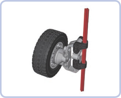
The final issue involving wheels is steering geometry. In most real cars, when the wheels are steered, they rotate around a pivot point—that is, a vertical axle that goes nearly through their center. As the wheel is turned left or right, its center stays in place, as shown in Figure 21-9. The only LEGO wheels that follow this behavior are from the 8448 Super Street Sensation set, shown in Figure 21-10. The other wheels rotate around a pivot point that is near their side but far from their center. This means that their centers actually move around when they are turned, as shown in Figure 21-11. LEGO portal axles are most problematic when it comes to steering geometry due to the distance between the wheel and the pivot point (see Figure 21-12).
The crucial difference between the two behaviors is the amount of free space required around the wheel in order for it to turn. Wheels with “real” steering geometry require very little space, and they fit within very tight mudguards. Wheels with the LEGO steering geometry require much more space, as they move back and forth relative to the body when being turned. This means that steered wheels in LEGO models need bigger mudguards than real steered wheels.
The difference in the size of the mudguards can also affect the look of the LEGO model. LEGO mudguards are larger than those of the original vehicle, and the wheels appear smaller inside them. Figure 21-13 shows the difference.
As you can see, wheels require careful consideration during the modeling process. It’s a common mistake to make them too small, which is more evident in a finished model than when they are too big. Many inexperienced builders produce otherwise well-designed models on wheels that are clearly too small. When in doubt, try to make your wheels too big rather than too small.
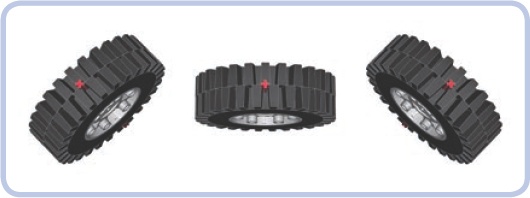
Figure 21-9. The steering geometry of a real vehicle’s wheel: As the wheel is steered, it rotates around a pivot point going through its center, marked in this series of images by an “imaginary” red axle.
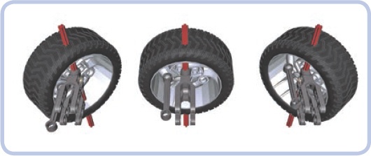
Figure 21-10. Of all existing LEGO wheels, only the 8448 set’s wheels rotate around their centers when steered—and they are still a little off
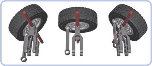
Figure 21-11. When steered, a typical LEGO wheel rotates around a pivot point that is often well outside it. It requires more free space around the wheel, and it also makes the front of the vehicle move while steering in place.
Circular parts are quite tricky to model. You either have to use ready-made pieces, whose variety and availability are limited, or create complex structures of many small pieces, which are fragile and can disintegrate in an instant if sufficient stress is applied. Figure 21-14 and Figure 21-15 show examples of such structures.
Colors are a tricky issue when it comes to LEGO pieces. Typical Technic sets use a fairly limited palette, with yellow and red being dominant. When choosing a color, you are always limited by the availability of LEGO pieces in a particular color, and it only gets worse with bigger, more complex models that require more pieces to be visible from the outside.
Over the years, more than 150 LEGO colors have been developed, including speckle colors, glitter colors, semitransparent colors, chrome colors, and even a glow-in-the-dark color. Some of the colors have been discontinued, while new ones are added every now and then. Some colors are actually very difficult to tell apart, such as the very light bluish-grey color that dominates the Mindstorms NXT sets and regular white. In terms of the number of pieces they’re used for, the top five LEGO colors are white, black, red, yellow, and blue.
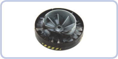
Figure 21-14. The 53983 turbine is an example of a singular circular piece that builders may find disappointing. Not only does it come with a pin hole instead an axle hole, which makes it difficult to drive, but also its inner and outer blades are set in opposite directions, making it useless as a propeller. Finally, the mixed colors appeal to few.
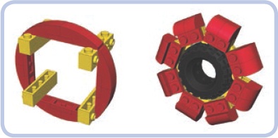
Figure 21-15. Two circular structures built with small basic pieces. One is built around bricks with studs on the side, and the second is built with hinge plates embracing a tire. Both are prone to disintegration if sufficient stress is applied.
When making use of colors in your models, remember that dividing a model into a few unicolored areas almost always produces a better effect than mixing colors. Due to the rectangular shape of most LEGO pieces, mixtures of variously colored pieces just don’t look good and make details difficult to spot.
Building the inside of your model in black conceals gaps in your model’s body. Dark colors also make your model appear larger. Keep in mind that it’s quite common for LEGO builders to substitute certain colors for others when they can’t match the actual vehicle exactly. The most common example is LEGO dark bluish grey, which builders often use in military models instead of khaki and olive, which have no LEGO counterparts.
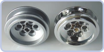
Sometimes it’s impossible to find a given LEGO piece in the color you desire, but few builders paint their pieces to remedy this issue. This is because painting rarely produces an effect even remotely close to a stock-colored LEGO piece and is often considered cheating in the community. But this isn’t true when it comes to chrome; any LEGO piece looks excellent when chromed, yet there are fewer than 100 types of originally chromed pieces. Consequently, many builders try custom-chroming regular LEGO pieces. The resulting size of the piece is slightly increased by the thin chrome film, so chromed pieces are best used for purely decorative purposes rather than as mechanical elements. During custom-chroming, one part of the piece is usually attached to another piece and remains free of the film; this is the only visible difference between original and custom-chromed LEGO pieces (see Figure 21-16). The two largest sources of custom-chromed LEGO pieces include the ChromeBricks shop, at http://chromebricks.com/, and Chrome Block City, at http://www.bricklink.com/store.asp?p=Aurimax.
When building LEGO models, we regularly have to build things smaller than our scale would indicate. It’s very difficult to model details smaller than a single stud, and that means that a lot of approximation is involved. Approximating means that some elements of your model will only vaguely resemble the real ones. You have to make some of them bigger or smaller than they should be and discard some elements entirely. Some builders also resort to custom-made stickers to reproduce the tiniest details.
The barrels of tanks are a particularly good example of approximate building. They almost always consist of a number of sections with slightly different diameters, and it’s difficult to find circular LEGO pieces whose differences in diameter are proportionally the same. Because of this, some parts of the barrel need to be built thinner or thicker, as shown in Figure 21-17. It’s important to consider the impression each of these deviations will create. People expect a tank to look threatening, which it does with a thick barrel. I have built many tanks with barrels too thick, and not a single person noticed it. But when I built one with a barrel too thin, I received plenty of complaints about it.
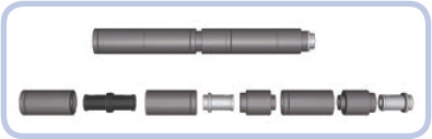
Figure 21-17. Two sections of my T-72M tank’s barrel. They are made of slightly different pieces, but they have identical dimensions and a clearly visible notch between them. The resulting barrel, over 20 studs long, is surprisingly sturdy.
A good way to plan a model is to decide which of its features are most important and to try to retain or even exaggerate those features. If the original object you chose has distinctive big wheels, high ground clearance, or an elongated silhouette, exaggerating those features (within reason) can ensure that your model will be easily recognized. Bear in mind that it’s easy to go over the top, as Figure 21-18 shows.
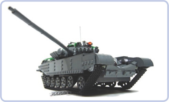
Figure 21-18. Exceptionally high ground clearance is one of the distinctive features of the real T-72M tank. This feature, however has been exaggerated in my model.
When looking for distinctive features, always try to think in three dimensions. For example, I have built two models of the Scania trucks, whose distinctive feature is a massive front grille with large horizontal openings. The first model simply used black plates to mimic the openings, and it looked very flat when compared to the real truck. So in the second model, shown in Figure 21-19 and Figure 21-20, I created 1-stud-deep openings closed with black plates, and this turned out much better.
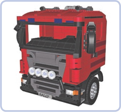
Figure 21-19. The cabin of my second model of the Scania truck with 1-stud-deep openings in its distinctive massive grille.
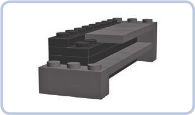
Figure 21-20. I created the openings in my Scania truck’s grille using a mixture of plates and tiles. It was crucial to make the ledges between the openings as thin as possible; they are only 1 tile thick here.
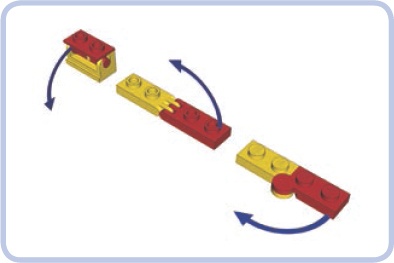
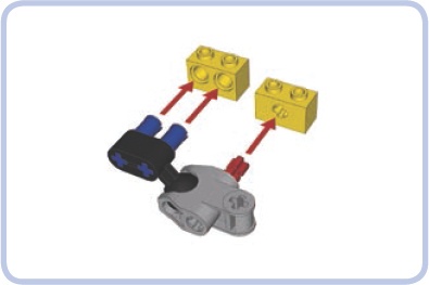
Both Technic and non-Technic connector pieces can be used to re-create complex angles. Certain vehicles, such as the armored personnel carrier shown in Figure 21-21, have bodies with almost no right angles. By building such models with plates and tiles joined by hinged connectors, shown in Figure 21-22, you can make them look good and weigh little. Some particularly challenging angles can be retained by using Technic connectors with ball joints; Figure 21-23 shows an example of this. Bionicle sets are a good source for these kinds of connectors.
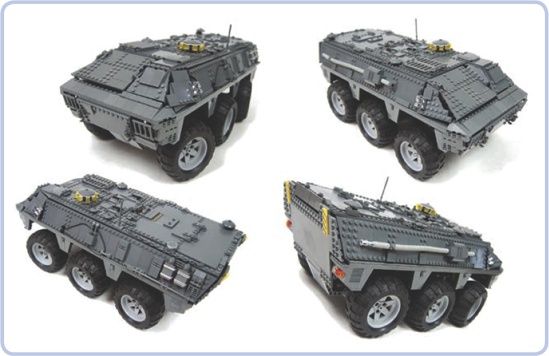
Figure 21-21. The Spanish BMR-2 is a typical armored personnel carrier, with a body made of surfaces connected at complex angles. My model had a body made of plates and tiles kept in place by a system of hinge plates.
When working on details, the crucial rule is to match the pieces to the details, not the details to the pieces. In other words, you should focus on how a detail looks and how to reproduce that look with LEGO pieces. Some builders make the mistake of focusing on some piece they want to use and then looking for a detail that looks vaguely similar.
Many objects have little details that are so distinctive that it’s best to include them. For example, when building a Land Rover S2 model, I tried to re-create its distinctive tilted fuel cap. As Figure 21-24 shows, I eventually succeeded using a variant of the 1×1 brick held at an angle between two regular 1×2 Technic bricks.
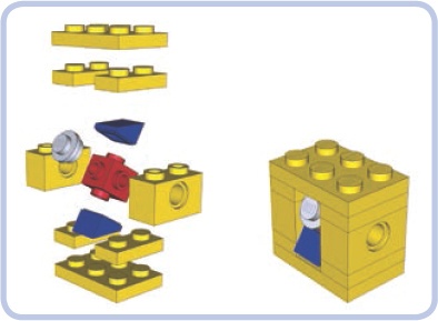
Figure 21-24. An exploded view and a complete assembly of my Land Rover S2 model’s tilted fuel cap. The key was using a variant of a 1×1 brick and setting it at an angle.
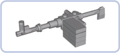
A number of tiny pieces, especially LEGO minifigures’ utensils, can be combined to great effect. For example, many tanks come with a commander’s gun on top of the turret. In large-scale models, these guns have plenty of details, and their look is often unique for a given type of tank. When building a model of the Leopard 2A4 tank, I had the choice to use some simple piece that looked like a gun to me or to use one of the few ready-made LEGO guns. Neither of these options produced an accurate-looking result, so I eventually combined a few minfigures’ utensils, creating the gun shown in Figure 21-25. The gun was built around the body of a minifigure chainsaw, with a hatchet attached in back and a telescope and a fire hose’s nozzle in front. The gun’s distinctive, large box magazine was made from a few plates with a tile on top, and it was attached to the gun with a 1×1 plate with a clip. The gun was a total of nine simple pieces, and the result prompted some viewers to ask for instructions to build it or for the address to buy the gun.
Finally, remember that the fun doesn’t have to end with building your model. Building a controller for complex models can be a challenge of its own, as exemplified by a model of the Demag H135 excavator built by Emil “Emilus” Oklrński (see Figure 21-26). The model uses two NXT bricks in conjunction with another two bricks in the remote to enable realistic remote control. The remote includes complex joysticks built around NXT motors with internal rotation counters, and it takes advantage of the Bluetooth link to connect with the model. Some functions of the model, such as its internal pneumatic compressor, are controlled automatically, and some of its working parameters can be read from the remote. An extensive description of Emil’s model is available at http://www.eurobricks.com/forum/index.php?showtopic=64131.
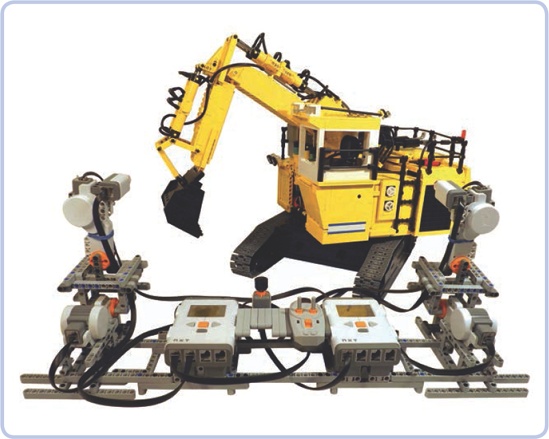
Figure 21-26. The Demag H135 model built by Emil “Emilus” Okliński employed four Mindstorms NXT bricks—two in the remote and another two in the model—to achieve realistic remote control. The complex joysticks based on NXT motors and the use of a Bluetooth link between the remote and the model provided the “driver” with an unparalleled experience.