
Chapter 4
Steam Power Cycles
4.1 ❐ INTRODUCTION
In steam power plants and refrigeration cycles, the working fluid changes from liquid to vapour and back to liquid state. This succession of processes is called vapour cycle. In steam power plants, water is the working fluid in the form of steam and vapour. In refrigeration cycles gasses such as Freon, CO2, and ammonia (aqua-ammonia) are used as working substances.
4.2 ❐ CARNOT VAPOUR CYCLE
The elements of steam power plants are as follows:
- Boiler
- Steam turbine
- Condenser
- Feed pump
The schematic diagram of a steam power plant is shown in Fig. 4.1. The p-v and T-s diagrams for the Carnot vapour power cycle are shown in Fig. 4.2(a) and (b). Dry and saturated steam at temperature TH = T1 enters the steam turbine and is expanded isentropically to sink temperature TL = T2 to do work. The exhaust steam from the turbine is condensed and cooled in the condenser to state 3 at which the working fluid is in a two-phase mixture of water and its vapour. The water and the vapour are then pumped by the boiler feed pump to state 4 in a saturated state to the boiler, where it is converted into steam.
Consider 1 kg of the working fluid for analysis.
Work done by steam turbine wt = w1 − 2 = h1 − h2
Work done on the pump, wp = w3 − 4 = hf4 − h3
Net work, wnet = w1 − wp = (h1 − h2) − (hf4 − h3)
= (h1 − hf4) − (h2 − h3) = qs − qr
Heat supplied, qs = h1 − hf4
and heat rejected, qr = h2 − h3

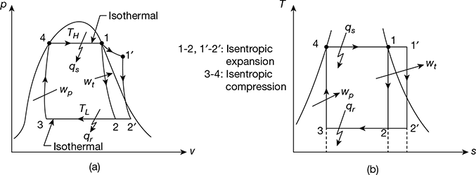
Figure 4.2 p-v and T-s diagrams for Carnot vapour cycle: (a) p-v diagram,(b) T-s diagram
Thermal efficiency, ![]()

From the second law of thermodynamics, we have
Similarly, ![]()
or qr = TL (s2 − s3)
Since, s1− s4 = s2 − s3, one can write
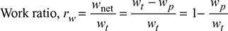
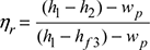
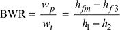
- Work Ratio (rw): It is defined as the ratio of net work done to turbine work done in the cycle.

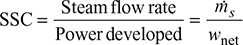
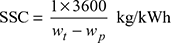
- Specific Steam Consumption (SSC): It is defined as the flow rate of steam per unit of power developed. It is expressed in kg/kWh.

- Heat Rate: It is defined as the rate of heat supplied to produce unit work output.

4.2.1 Drawbacks of Carnot Cycle
The major drawbacks of Carnot cycle are as follows:
- It is very difficult to build a pump which can pump isentropically a two-phase mixture of water and its vapour at state point 3 and to deliver saturated water at state point 4.
- It is very difficult to superheat steam at constant temperature along path 1–1′.
- The steam leaving the turbine is of very low dryness fraction. It causes erosion and pitting on turbine blades.
- The volume of water vapours to be handled by the pump is quite large. It requires a very largesized pump, thus resulting in high power consumption.
- It requires high specific steam consumption, giving low thermal efficiency. Hence, it is not economically viable.
Example 4.1
A steam power plant operates on an ideal Carnot cycle. Dry saturated steam at 20 bar pressure is supplied to a turbine. It expands isentropically to a condenser pressure of 0.075 bar. Assuming that saturated water enters the boiler, calculate (a) the thermal efficiency, (b) the work ratio, and (c) the specific steam consumption.
Solution
For dry saturated steam at 20 bar, from the steam tables, we have
h1 = hg = 2799.5 kJ/kg, s1 = sg = 6.3408 kJ/kg.K
At 0.075 bar condenser pressure, from the steam tables, we have
hf2 = 168.77 kJ/kg, hfg2 = 2406.0 kJ/kg,
sf2 = 0.5763 kJ/kg.K, sfg2 = 7.6751 kJ/kg.K
Now s1 = s2 = sf2 + x2 sfg2 for the isentropic expansion process 1−2. (Fig.4.2)
6.3408 = 0.5763 + x2 × 7.6751
or x2 = 0.751
∴ h2 = hf2 + x2hfg2 = 168.77 + 0.751 × 2406.0 = 1975.676 kJ/kg
At 20 bar, we have
hf4 = 908.77 kJ/kg, s4 = sf4 = 2.4473 kJ/kg.K
For the isentropic compression process 3−4, we have
s3 = s4
or sf3 + x3 sfg3 = s4
Now sf3 = sfg3 and sfg3 = sfg2
0.5763 + x3 × 7.6751 = 2.4473
or x3 = 0.244
hf3 = hf2 and hfg3 = hfg2
h3 = hf3 + x3 hfg3 = 168.77 + 0.244 × 2406.0 = 755.834 kJ/kg
Pump work, wp = hf4 − h3 = 908.77 − 755.834 = 152.936 kJ/kg
Turbine work, wt = h1 − h2 = 2799.5 − 1975.676 = 823.824 kJ/kg
Net work, wnet = wt − wp = 823.824 − 152.936 = 670.888 kJ/kg
Heat supplied, qs = h1 − hf4 = 2799.5 − 908.77 = 1890.73 kJ/kg
- Thermal efficiency

- Work ratio,

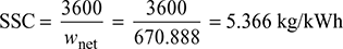
- Specific steam consumption,
4.3 ❐ RANKINE CYCLE
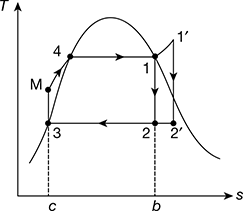
The schematic of Rankine cycle is shown in Fig. 4.3(a). It consists of a turbine, boiler, condenser, and pump. The p-v diagram is shown in Fig. 4.3(b) and the T-s diagram in Fig. 4.3(c). The delivery of steam from the boiler takes place at state 1 when assumed dry saturated or 1′ when assumed superheated. The steam expands isentropically in the prime mover to state point 2 from point 1 and 2′ from 1′.
After doing work at point 2 or 2′, the steam is condensed in the condenser to saturated water, represented by point 3 at pressure p2. This water is compressed isentropically to pressure p2 by the pump represented by the process 3−M. Thus, the boiler receives water at pressure p1 in a sub-cooled state, heats it to temperature corresponding to point 4, and further transforms it into steam at constant pressure p1. M−4−1 is the operation carried out in the boiler for dry saturated steam and M−4−1′ for superheated steam. All processes except the process of mixing of cold water at point M with hot water at point 4 are reversible. However, when we consider the flow of constant mass, this process gets deleted. The cycle begins again at 1 or 1′.
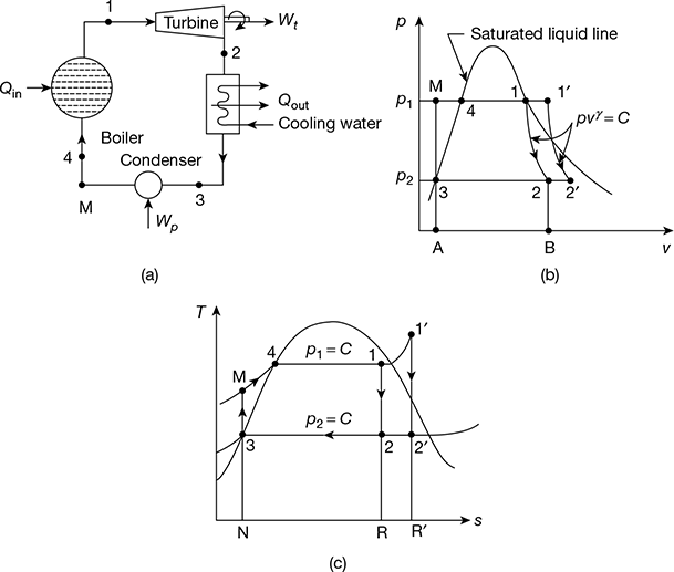
Figure 4.3 Rankine cycle: (a) Schematic diagram, (b) p-v diagram, (c) T-s diagram
4.3.1 Analysis of Rankine Cycle
Let h1 = enthalpy of steam at point 1
h2 = enthalpy of steam at point 2
hf3 = enthalpy of water at point 3
hf4 = enthalpy of water at point 4
hfM = enthalpy of water at point M
Heat added at constant pressure p1 represented by M−4−1,
qa = h1 − hfM = (h1 − hf3) − (hfM − hf3)
= area N−M−4−1−R−N on T-s diagram
Heat rejected at constant pressure p2 represented by 2−3,
qr = h2 − hf3
= area R−2−3−N−R on T-s diagram
Net work done, wnet = qa − qr
Pump work, wp = hfM − hf3
wnet = (h1 − h2) − wp
qa = (h1 − hf3) − wp
Now wp = 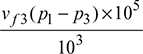 = vf3 (p1 − p3) × 102 kJ/kg, where p is in bar.
= vf3 (p1 − p2) × 102 kJ/kg
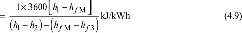
Thermal efficiency, ![]()

Neglecting pump work, which is small as compared to other quantities.
Overall heat rate (OHR) = Specific steam consumption × heat supplied per kg of throttle steam
Example 4.2
In an ideal Rankine cycle, saturated steam vapours enter the turbine at 160 bar and saturated liquid exits the condenser at 0.05 bar. The net power output of the cycle is 130 MW. Determine for the cycle (a) the thermal efficiency, (b) the steam mass flow rate, and (c) the specific steam consumption.
Solution
The Rankine cycle is shown in Fig. 4.4.
From steam tables,
For p1 = 160 bar, h1 = hg = 2580.6 kJ/kg, s1 = sg1 = 5.2454 kJ/kg.K
p2 = 0.05 bar, vf3 = 0.001005 m3/kg, vg3 = 28.193 m3/kg, hf3 = 137.79 kJ/kg,
hfg3 = 2423.7 kJ/kg, sf3 = 0.4763 kJ/kg.K, sfg3 = 7.9187 kJ/kg.K
For insentropic process 1−2,
s1 = s2 = sf3 + x2sfg3
or 5.2454 = 0.4763 + x2 × 7.9187
or x2 = 0.602
h2 = hf3 + x2hfg3 = 137.79 + 0.602 × 2423.7 = 1596.86 kJ/kg
h3 = hf3 = 137.79 kJ/kg
hM = h3 + vf3 (p1 − p2) × 102
Turbine work, wt = h1 − h2 = 2580.6 − 1596.86 = 983.74 kJ/kg
Pump work, wp = hM − h3 = 153.86 − 137.79 = 16.07 kJ/kg
Heat added qa = h1 − hM = 2580.6 − 153.86 = 2426.74 kJ/kg
- Thermal efficiency =

- Steam mass flow rate,

- Specific steam consumption,
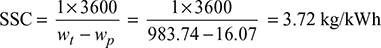

Figure 4.4 Ideal Rankine cycle
Example 4.3
In a steam power plant working on ideal Rankine cycle, the steam turbine receives steam at 10 bar 250°C and discharges at 0.5 bar. Find the thermal efficiency.
Solution
At p1 = 10 bar, ts = 179.91°C. Therefore, steam is superheated. The T-s diagram is shown in Fig. 4.5.

Figure 4.5 Rankine cycle
From steam tables, at 10 bar, 250°C,
h′1 = 2942.6 kJ/kg, s′1 = 6.9246 kJ/kg.K
At p2 = 0.5 bar, vf3 = 0.001030 m3/kg, hf3 = 340.47 kJ/kg, hfg3 = 2305.4 kJ/kg, sf 3 = 1.091 kJ/kg.K,
sfg3 = 6.5029 kJ/kg.K,
or 6.9246 = 1.091 + x′2 × 6.5029
or x′2 = 0.897
Pump work, wp = vf3 (p1−p2) × 102 = 0.001030 (10 − 0.5) × 102 = 0.9785 kJ/kg
Net work output ![]()
Heat added ![]()
Thermal efficiency ![]()
4.3.2 Effect of Boiler and Condenser Pressure
The Rankine cycle comprises internally reversible processes. Thus, the equation for thermal efficiency can be written in terms of average temperatures of heat addition and heat rejection processes.
With reference to Fig. 4.6, we have
Heat addition, qa = area 1−b−c−M−4−1

Heat rejected, qr = area 2−b−c−3−2
Thus ηth increases if Tout decreases or Tin increases. Therefore, Eq. (4.11) can be used to study the effects on the performance of the changes in boiler and condenser pressures.
- Effect of boiler pressure: Consider two different cases having same condenser pressure but different boiler pressures as shown in Fig. 4.7(a). The average temperature of heat addition is higher for higher pressure cycle 1′-2′-3-M′-1′ than for cycle 1-2-2-3-M-1. Thus, increase of boiler pressure leads to increase in the thermal efficiency of Rankine cycle.
- Effect of condenser pressure: Figure 4.7(b) shows two ideal Rankine cycles with the same boiler pressure but two different condenser pressures. One condenser operates at atmospheric pressure and the other at pressure less than atmospheric. The temperature of heat rejection for the cycle 1−2′′−3′′−M′′−1 is correspondingly lower than that for cycle 1−2−3−M−1. Thus, the cycle 1−2′′−3′′−M′′−1 has higher thermal efficiency. Therefore, decreasing the condenser pressure increases the thermal efficiency.

Figure 4.7 Effect of boiler and condenser pressure on Rankine cycle efficiency: (a) Effect of increase of boiler pressure, (b) Effect of decrease of condenser pressure
4.4 ❐ METHODS OF IMPROVING EFFICIENCY
The efficiency of the Rankine cycle can be improved by the following methods:
- Reheating
- Regeneration
- Combination of reheating and regeneration
4.4.1 Reheat Cycle
Figure 4.8(a) shows the schematic diagram for the reheat cycle. The corresponding h-s and T-s diagrams are shown in Fig. 4.8(b) and Fig. 4.8(c), respectively. The steam is extracted at a suitable point and is reheated with the help of flue gases in the boiler furnace. This increases the dryness fraction of steam passing through the LP turbine.
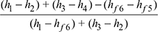
Heat supplied, qs = (h1 − hf6) + (h3 − h2)
Pump work, wp = hf 6 − hf5
Turbine work, wt = (h1 − h2) + (h3 − h4)
Net work output, wnet = wt − wp
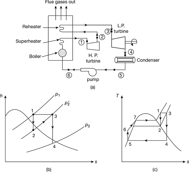
Figure 4.8 Reheat cycle: (a) Schematic diagram, (b) h-s diagram, (c) T-s diagram

If pump work is neglected,
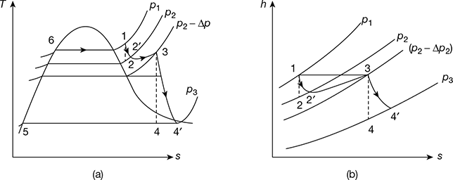
4.4.2 Effect of Pressure Drop in the Reheater
The T-s and h-s diagrams for a reheat cycle with pressure drop is shown in Fig. 4.9(a) and (b), respectively. Steam enters the prime mover first stage at point 1. Line 1-2 is the isentropic process. However, in actual practice, it is an irreversible process due to internal frictional resistance offered to the flow of steam. Thus, the condition after the irreversible adiabatic expansion is shown by point 2′. The steam at condition 2′ is passed on the reheater. Since steam cannot pass through the reheater without a pressure drop, the exit from the reheater at point 3 account for the reheater pressure drop from p2 to p2 − Δp. The steam then expands irreversibly and adiabatically to point 4′.
For the first stage, turbine efficiency, ![]()
And for the second stage, ![]()

Example 4.4
A high pressure boiler delivers steam at 90 bar and 480°C. The steam is expanded in the first stage of turbine to 12 bar and withdrawn and passed on the reheater. The expansion now takes place in the second stage of the steam turbine, down to the condenser pressure of 0.07 bar. Calculate (a) the efficiency of the ideal cycle and (b) the work output and efficiency of the reheat cycle operating through the same states neglecting pump work.

Solution
The cycle on T-s diagram is shown in Fig. 4.10.
At 90 bar, 480°C, from steam tables,
h1 = 3336.5 kJ/kg, s1 = 6.5942 kJ/kg.K
Now, s1 = s2
Since, sg at 12 bar is less than 6.5942, the state 2 is in the superheated region. then, we get
h2 = 2814.4 kJ/kg, t2 = 201°C
At 12 bar, 480°C, h3 = 3432.8 kJ/kg, s3 = 7.6198 kJ/kg.K
At 0.07 bar, sf4 = 0.5589 kJ/kg.K, sfg4 = 7.7179 kJ/kg.K
or 7.6198 = 0.5589 + x4 × 7.7179
or x4 = 0.915
h4 = hf4 + x4hfg4 = 163.40 + 0.915 × 2409.1 = 2367.7 kJ/kg
hfs = hf4 = 163.4 kJ/kg
h6 = h5 + wp
wp = vfs (p1 − p2) × 102
= 0.001007 (90 − 0.07) × 102 = 9 kJ/kg
h6 = 163.4 + 9 = 172.4 kJ/kg
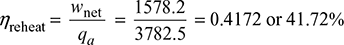
- qa = (h1 − h6) + (h3 − h2) = (3336.5 − 172.4) + (3432.8 − 2814.4) = 3782.5 kJ/kg
wnet = (h1 − h2) + (h3 − h4) − wp
= (3336.5 − 2814.4) + (3432.8 − 2367.7) − 9 = 1578.2 kJ/kg
- Neglecting pump work
qa = 3782.5 + 9 = 3781.5 kJ/kg
wnet = 1578.2 + 9 = 1587.2 kJ/kg

Example 4.5
In Example 4.4, steam enters the reheater at 12 bar, 210°C, and leaves at 11.5 bar, 480°C. The combined steam rate is 3 kg/kWh, the generator efficiency is 94%, and the heat loss through the turbine casing is 1% of the throttle enthalpy. Determine the turbine thermal efficiency and condition of exhausted steam.
Solution
The processes in the T-s diagram is shown in Fig. 4.11.
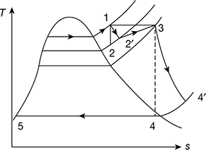
Figure 4.11 Reheat Rankine cycle with turbine efficiency
Refer to Fig. 4.11
![]() = 210°C,
= 210°C, ![]() = 12 bar, t3 = 480°C, p3 = 11.5 bar
= 12 bar, t3 = 480°C, p3 = 11.5 bar
Now h1 = 3336.5 kJ/kg, h2 = 2814.4 kJ/kg
![]() at 12 bar, 210°C from steam tables
at 12 bar, 210°C from steam tables
= 2839.8 kJ/kg
h3 at 11.5 bar, 480°C = 3433.4 kJ/kg
Now ![]()
For energy balance of turbine,
h1 + h3 = h′2 + ![]() + wnet + qloss
+ wnet + qloss
![]() = h1 −
= h1 − ![]() + h3 − wnet − 0.01 × h1
+ h3 − wnet − 0.01 × h1
At p4 = 0.07 bar, ![]() = 2620.1 kJ/kg,
= 2620.1 kJ/kg, ![]() = 64°C
= 64°C
Since saturation temperature at 0.07 bar is 39.02°C, the exhaust steam is superheated and the degree of superheat is 24.98°C.
Efficiency of turbine upto extraction point,
Overall efficiency of turbine,
Example 4.6
Steam at 100 bar and 500°C enters a prime mover that has one stage of reheat. The steam is exhausted from the prime mover at 0.07 bar and 85% dry. The net work developed by the prime mover is 1600 kJ/kg of steam. Calculate the thermal efficiency of the prime mover.
Solution
The cycle on T-s diagram is shown in Fig. 4.12.
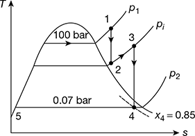
Figure 4.12 Reheat Rankine cycle
Refer to Fig. 4.12.
From steam tables for p1 = 100 bar, 500°C,
h1 = 3373.6 kJ/kg
At 0.07 bar, hf5 = 163.38 kJ/kg
h4 = hf4 + x4 hfg4
= 163.38 + 0.85 × 2409.2 = 2211.2 kJ/kg
wnet = 1600 kJ/kg
or h3 − h2 = wnet + h4 − h1 = 1600 + 2211.2 − 3373.6 = 435.6 kJ/hg
Thermal efficiency ηth = ![]()
4.5 ❐ REGENERATION
In the Rankine cycle and reheat, the condensate which is at a fairly low temperature is pumped to the boiler. Thus, there is an irreversible mixing of the cold condensate with hot boiler water. This results in loss of cycle efficiency. Regeneration is a method to heat the feed water from the hot well of the condenser reversibly by interchange of heat within the system, thus improving the cycle efficiency. The cycle is called regenerative cycle.
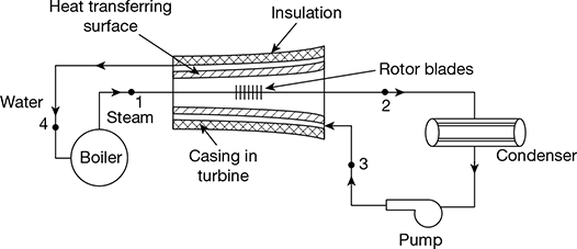
In Fig. 4.13, steam is drawn from the boiler at state point 1 and passes through the turbine and goes to the condenser at state point 2. If no heat is transferred from this steam to the surrounding, which include the casing, and the expansion is isentropic. This process is shown by line 1−2′ in the T-s diagram (Fig. 4.14). However, in the regenerative cycle, it is assumed that the condensate after being pumped to the boiler pressure at state point 4 passed through the hollow casing surrounding the turbine rotor to the boiler. Therefore, the steam losses heat to the surrounding water which gets heated. The temperature of steam entering the turbine and temperature of water leaving the turbine are same.
Let T1 = saturation temperature of steam at the commencement of expansion at state point 1.
T3 = temperature of saturated water condensate entering the hollow casing of turbine at state point 3. Thus, 1 kg of water is gradually heated along the path 3−4 and 1 kg of steam gradually loses the same amount of heat during expansion process 1−2. Such a heat exchange within the system is called regenerative heating. Therefore, the net heat supplied to the system is in the boiler during process 4−1 and the net heat rejected from the system is in the condenser during process 2−3 (Fig. 4.14).
Heat added, qa = T1 (s1 − s4)
Heat rejected, qr = T2 (s2 − s3)
Net work done,
wnet = qa − qr
= T1 (s1 − s4) − T2 (s2 − s3)
But s1 − s4 = s2 − s3
∴ wnet = (T1 − T2) (s1 − s4)

Figure 4.14 T-s diagram for regenerative Rankine cycle

This method of regeneration is not practicable because the steam becomes extremely wet at the later stages of expansion.
4.5.1 Regenerative Cycle with Open Heaters
The regeneration effect can be achieved by bleeding or extracting small quantities of steam at different points during the expansion and exploiting the energy of bled steam rather than whole steam. Thus, that part of the steam which continues to expand and to do work, does not condense excessively. A regenerative cycle with three bleeding points and therefore, three open type heaters, where feed water and steam mix, is shown in Fig. 4.15. The corresponding T-s diagram is shown in Fig. 4.16.
Let 1 kg of steam enter the turbine at state point 1 and expand to the state point 2 where m1 kg of steam is extracted from the turbine and passed on to the heater 3. The remainder (1 − m1) kg of steam continues to expand isentropically to state points 3 where m2 kg of steam is extracted and passed on the heater 2. The remainder (1 − m1 − m2) kg of steam further continues to expand isentropically to state point 4 where m3 kg of steam is bled and passed on to heater 1. Thus, only (1 − m1 − m2 − m3) kgof steam does the remaining isentropic expansion to point 5 before entering the condenser, where it is condensed to point 6. The condensate (1 − m1 − m2 − m3) kg at enthalpy b6 is mixed in heater 1. m3 kg of steam bled at state point 4 condenses to state point 7 and (1 − m1 − m2 −m3) kg of water gets heated from b6 to point 7. (1 − m1 − m2) kg of feed water at state point 7 is pumped to heater 2 at state point by. In the heater (1 − m1 − m2) kg of feed water is heated from state point 7 to state point 8 and m2 kg of bled steam from point 3 condenses to point 8. Thus, heater 2 has (1 − m1) kg of feed water at point 8 which is pumped to heater 3 raising the enthalpy of pumped feed water to b8. This feed water in heater 3 gets heated to point 9 by condensation of m1 kg of steam bled from point 2, leaving 1kg of feed water in heater 3 to be pumped to boiler pressure by raising its enthalpy to b9. Heating of 1 kg of feed water from b9 to point 10 is done in the boiler where it is further heated to steam at point 1.

Figure 4.15 Regenerative feed water heating with open heaters
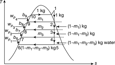
Figure 4.16 T-s diagram for feed heating with open heaters
For simplified analysis, points 6 and b6, 7 and b7, 8, and b8, 9 and b9 are treated as coincident points, thus ignoring the very small quantity of pump work. Thus, we have
Heat gained by feed water = Heat lost by bled steam
Heater 1: (1 − m1 − m2 − m3) (h7 − h6) = m3 (h4 − h7)
Heater 2: (1 − m1 − m2) (h8 − h7) = m2 (h3 − h8)
Heater 3: (1 − m1) (h9 − h8) = m1 (h2 − h9)
Net work output, wout = (h1 − h2) + (1 − m1) (h2 − h3) + (1 − m1 − m2) (h3 − h4) + (1 − m1 − m2 − m3)(h4 − h5)
wnet = wout − ∑wp
Heat added, qa = h1 − hb9 = h1 − h9 − wp4
Now ∑wp = (1 − m1 − m2 − m3) (hb6 − h6) + (1 − m1 − m2) (hb7 − h7) + (1 − m1) (hb8 − h8) + (hb9 − h9)
= vf6(p1 − p6)
where p1 = throttle pressure, p6 = condenser pressure and vf6 = specific volume of water at condenser pressure.
4.5.2 Regenerative Cycle with Closed Heaters
In this type of heater, the feed water is contained in the tubes about which the bled steam passes and condenses. One pump can be used for two or more heaters placed in series. The heaters can be placed in various combinations. One such arrangement is shown in Fig. 4.17. The corresponding T-s diagram is shown in Fig. 4.18.
Work done per kg of steam supplied to turbine,
Total pump work, ∑wp = wp1 + wp2 + wp3
where h6 − h5 = vf5 (p1 − p4) × 102 kJ/kg
h10 − h9 = vf9 (p1 − p3) ×102 kJ/kg
h12 − h11 = vf11 (p1 − p2) × 102 kJ/kg
where vf is in m3/kg and p is in bar.
Now, vf5 = vf9 = vf11 = saturated volume of water
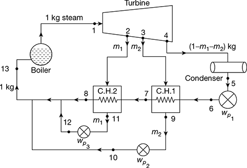

Figure 4.18 T-s diagram for regenerative Rankine cycle with closed heaters
Net work done, wnet = wt − ∑wp
Heat added in the boiler, qa = h1 − hf13

Neglecting heat losses and considering heat balance at feed heaters, we have
m2 (h3 − hf9) = (1 − m1 − m2) (hf9 − hf 5)
and m1 (h2 − hf11) = (1 − m1 − m2) (hf11 − hf9)
Neglecting enthalpy increase due to pump,
hf6 = hf5
also hf7 = hf9
and hf8 = hf11
The condition of feed water h13 entering the boiler is given by,
(1 − m1 − m2) hf11 + m2hf9 + m1hf11 = 1 × h13
or h13 = (1 − m2) hf11 + m2hf 9
Example 4.7
A boiler feeds a turbine at 56 bar and 600°C. Before being passed on to the condenser at 30°C, the steam is bled for regenerative feed heating at 6.5 bar. For an ideal regenerative cycle and 1kg/s of throttle steam, determine (a) the amount of bled steam, (b) net work done, and (c) the ideal efficiency of the cycle.
Solution
The T-s diagram is shown in Fig. 4.19.
At p1 = 56 bar, 600°C from steam tables,
h1 = 3659.5 kJ/kg, s1 = 7.2011 kJ/kg.K
At 6.5 bar, h2 = 2987 kJ/kg
and t2 = 265°C
s3 = s1 = sf3 + x3 sgh3
At 30°C, sf3 = 0.4369 kJ/kg.K, sfg3 = 8.01674 kJ/kg.K
or 7.2011 = 0.436 + x3 × 8.0164
or x3 = 0.8438
h3 = hf3 + x3hgh3 = 125.79 + 0.8438 × 2430.5 = 2176.6 kJ/kg
At 6.5 bar, hf6 = 684.26 kJ/kg, vf6 = 0.001104 m3/kg
h7 = hf6 + vf6 (p1 − p2) × 102 = 684.26 + 0.001104 (56 − 6.5) × 102
= 684.26 + 5.47 = 689.72 kJ/kg
wp2 = 5.47 kJ/kg
vf4 = 0.001004 m3/kg
p4 corresponding to 30°C = 0.042461 bar
wp1 = vf 4 (p2 − p4) = 0.001004(6.5 − 0.042461) × 102
= 0.648 kJ/kg
∑wp = wp1 + wp2 = 0.648 + 5.47 = 6.118 kJ/kg
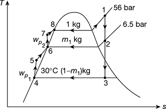
Figure 4.19 Regenerative Rankine cycle with a single heater

Example 4.8
Determine the improvement of efficiency which would results if a single stage of regenerative feed heating were added to a steam cycle having terminal conditions of 16 bar, 300°C and 0.05 bar. The steam for feed heating is to be extracted at 1.16 bar. The drain from the heat exchanger at saturation temperature of bled steam pressure is returned to the system at a point downstream from the heat exchanger, the feed water getting heated to saturation temperature at pressure of bled steam. Neglect change in enthalpy due to liquid pump work.
Solution
The regenerative cycle and h-s diagram is shown in Fig. 4.20(a) and (b).
From the Mollier diagram,
From steam tables, hf1 = 856.6 kJ/kg, hf2 = 475.4 kJ/kg, hf3 = 137.8 kJ/kg
For heat balance of heater,
m (h2 − hf3) = (hf2 − hf3)
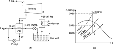
Figure 4.20 Single stage regenerative heating Rankine cycle: (a) Schematic diagram, (b) Mollier diagram

wnet = (h1 − h2) + (1 − m) (h2 − h3)
= (3035 − 2575) + (1 − 0.138) (2575 − 2098) = 871 kJ/kg
qa = h1 − hf2 = 3035 − 475.4 = 2559.6 kJ/kg
Thermal efficiency with regeneration, ![]()
Without feed water heating,
wnet = h1 − h3 = 3035 − 2098 = 937 kJ/kg
qa = h1 − hf3 = 3035 − 137.8 = 2897.2 kJ/kg
Thermal efficiency without regeneration, ![]()
Improvement in thermal efficiency = ![]()
Example 4.9
A regenerative cycle with three-stage bleed heating works between 30 bar, 450°C, and 0.04 bar. The bleed temperatures are chosen at equal temperature ranges. Determine the efficiency of the cycle. Neglect the pump work.
Solution
The schematic diagram of the cycle, T-s, and h-s diagrams are shown in Fig. 4.21(a) to (c).
At p = 0.04 bar, ts = 30°C
Temperature range = 450 − 30 = 420°C
Equal temperature difference = ![]()
The temperatures of bled steam are: 450 − 105 = 345°C, 240°C, 135°C
From Mollier chart,
h1 = 3340 kJ/kg, h2 = 3150 kJ/kg, h3 = 2935 kJ/kg,
h4 = 2720 kJ/kg, hs = 2120 kJ/kg
The pressure at 2, 3, 4 points are noted from the h-s chart. Then from steam tables,
hf1 = 1008.35 kJ/kg, hf2 = 837.45 kJ/kg, hf3 = 684.0 kJ/kg,
hf4 = 517.62 kJ/kg, hf5 = 121.4 kJ/kg
For heat balance of heaters,
m3 (h4 − hf4) = (1 − m1 − m2 − m3) (hf4 − hf5)
m2 (h3 − hf3) = (1− m1 − m2 − m3) (hf3 − hf4)
m1 (h2 − hf2) = (1 − m1) (hf2 − hf3)
∴ m3 (2720 − 517.62) = (1 − m1 − m2 − m3) (517.62 − 121.4)
or 2202.38 m3 = (1 − m1 − m2 − m3) × 396.22
m2 (2935 − 684) = (1 − m1 − m2) (684 − 517.62)
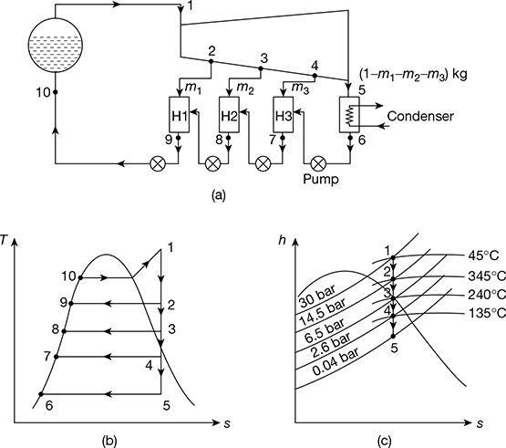
Figure 4.21 Regenerative Rankine cycle with three-stage bleeding: (a) Schematic diagram, (b) T-s diagram, (c) h-s diagram
or 2251 m2 = (1 − m1 − m2) × 166.38
m1 (3120 − 837.45) = (1 − m1) (837.45 − 684)
or 2282.55 m1 = (1 − m1) × 153.45
Solving the above three equations, we get
m1 = 0.063 kg, m2 = 0.0645 kg, m3 = 0.1332 kg
Net work done, wnet = 1 × (h1 − h2) + (1 − m1) (h2 − h3) + (1 − m1 − m2) (h3 − h4) + (1 − m1 − m2 − m3)(h4 − h5)
= (3340 − 3120) + (1 − 0.063) (3120 − 2935) + (1 − 0.063 − 0.0645) (2935 − 2720) + (1 − 0.063 − 0.0645 − 0.13327) (2720 − 2120) = 1024.6 kJ/kg
Heat added, qa = h1 − hf2 = 3340 − 837.45 = 2502.55 kJ/kg
Thermal efficiency of the cycle, ![]()
4.6 ❐ REHEAT-REGENERATIVE CYCLE
Reheating is mainly adopted to gain advantage of drier steam in the low pressure stages, and regeneration is adopted for increasing the thermal efficiency of the cycle. Therefore, it is advisable to execute cycle adopting both reheat and regeneration. Figure 4.22(a) shows the schematic diagram of such a cycle with two-stage regeneration and one-stage reheating at first bleeding point. The same cycle is represented on T-s diagram in Fig. 4.22(b).
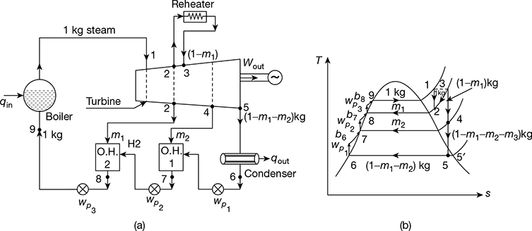
At point 2, m1 kg of steam is extracted from the turbine and is passed on to open heater 2 and the remaining (1 − m1) kg steam goes to reheater. The steam from the reheater comes back to the turbine at state point 3. Thereafter, (1 − m1) kg of steam expands from state point 3 to state point 4. At point 4, again m2 kg of steam is extracted and passed on to open heater 1. From state point 4, (1 − m1 − m2) kg of steam expands to condenser pressure state point 5, and further condenses in the condenser to water down to state point 6. Neglecting pump work, net work output from the prime mover is given by,
wout = (h1 − h2) + (1 − m1) (h3 − h4) + (1 − m1 − m2) (h4 − h5)
Net work of the cycle, wnet = wout − ∑wp
where ∑wp = wp1 + wp2 + wp3
= (1 − m1 − m2) (hb6 − h6) + (1 − m1) (hb7 − h7) + (hb8 − h8)
≃ vf6 (p1 − p6) × 102 kJ/kg
Heat added, qa = (h1 − hf8) + (1 − m1) (h3 − h2) − ∑wp
Thermal efficiency, ![]()
4.7 ❐ PROPERTIES OF AN IDEAL WORKING FLUID
An ideal working fluid should have the following favourable properties:
- Plentiful and cheap availability
- Non-toxic
- Chemical stability
- Non-corrosiveness
- High critical temperature
- Saturation pressure should be above atmospheric pressure to guard against leakage
4.8 ❐ BINARY VAPOUR CYCLES
In a binary vapour cycle, two working substances are used—one with good characteristics at high temperature and the other with good at low temperature characteristics. Figures 4.23(a) and (b) show two Rankine cycles in a combined arrangement. The heat is rejected from the high temperature cycle (mercury cycle) as energy supplied to the low temperature cycle (steam cycle). This occurs in a heat exchanger which functions as the condenser for mercury cycle and boiler for the water cycle. Specific enthalpy increase of water as it passes through the heat exchanger is several times the magnitude of the specific enthalpy decrease of mercury. Thus, the mass of mercury circulated in mercury cycle is several times more than mass of water in the water cycle. Binary vapour power cycles have a great advantage of its operation at high average heat addition temperature than conventional water cycles and give higher thermal efficiency.
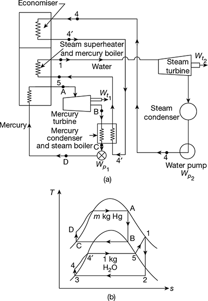
Figure 4.23 Binary vapour cycles: (a) Schematic diagram, (b) Mercury and steam cycles
Mercury cycle A−B−C−D−A is a simple Rankine cycle using saturated vapour. Heat is supplied to mercury in the process D−A. Mercury expands in process A−B and is condensed in process B−C. Mercury-saturated liquid is compressed in feed pump from condenser pressure to boiler pressure in process C−D. Thus, the Rankine cycle on mercury is completed.
Heat rejected during condensation in the mercury condenser is supplied to water to transform water into saturated steam in process 4−5. Process 4−5 may take place partly in the economiser located in the exhaust gases of mercury boiler and partly in the mercury condenser. The saturated vapour is superheated in the superheater located in the mercury boiler furnace process 5−1. Ideal process 4−4′occurs in the economiser and 4′−5 in the mercury condenser. Superheated steam expands in the turbine, process 1−2, and then condenses in the steam condenser, process 2−3. The condensate or feed water is then pumped by process 3−4, and heated till it is saturated liquid in the economiser as shown by process 4−4′, before going to the mercury condenser - steam boiler where enthalpy of evaporation is absorbed.
Let m = flow rate of mercury in the mercury cycle for 1 kg steam being circulated in steam cycle.
Heat added, Qa = m (hA − hD) + (h1 − h5) + (![]() − h4)
− h4)
Heat rejected, Qr = (h2 − h3)
Workdone by steam and mercury turbines,
Wt = m (hA − hB) + (h1 − h2)
Workdone on the feed pumps for mercury liquid and water,
Wp = m (hD − hC) + (h4 − h3)
Thermal efficiency of binary cycle,
The mercury cycle is known as topping cycle and the steam cycle is known as bottoming cycle.
Example 4.10
A binary vapour cycle consists of two ideal Rankine cycles with mercury and steam as working substances. The following data is given:
Saturated mercury vapour pressure at entry to turbine = 4.5 bar
Mercury vapour exit pressure from turbine = 0.04 bar
Saturated steam generated in mercury condenser pressure = 15 bar
Steam superheated temperature in superheater in mercury boiler = 300°C
Condensate water pressure pumped through economiser located in exhaust flue of mercury boiler to saturation temperature = 15 bar
Isentropic efficiency of mercury turbine = 0.85
Isentropic efficiency of steam turbine = 0.88
Calculate (a) the overall thermal efficiency of the cycle and (b) the rate of flow of mercury turbine in kg/h.
Properties of saturated mercury

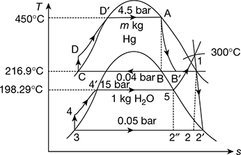
Solution
Refer to Fig. 4.24.
Mercury cycle
hA = 3559 kJ/kg, pA = 4.5 bar, tA = 450°C, sA = 0.5397 kJ/kg.K
Now sA = sfB + xB (sgB − sfB)
or 0.5397 = 0.0808 + xB (0.6925 − 0.0808)
or xB = 0.75
hB = hfB + xB (hgB − hfB) = 29.98 + 0.75 (329.85 − 29.98) = 254.88 kJ/kg
hB′ = hA − (hA − hB) ηt1 = 355.98 − (355.98 − 254.88) × 0.85 = 270.04 kJ/kg
pB′ = 0.04 bar, tB′ = 216.9°C
hc = hfc = 29.98 kJ/kg, tc = 216.9°C
hD = hc + vfc (pD − pC) × 102 = 29.98 + 76.5 × 10⁻⁶ (4.5 − 0.04) × 102 = 30.0142 kJ/kg
wp1 = vfc (pD − pC) × 102 = 0.03412 kJ/kg
Steam cycle
p1 = 15 bar, t1 = 300°C, h1 = 3038.9 kJ/kg, s1 = 6.9207 kJ/kg. K
p2 = 0.05 bar, hf2 = 137.77 kJ/kg, hg2 = 2561.6 kJ/kg, sf2 = 0.4763 kJ/kg.K,
h5 = 2789.9 kJ/kg, h4′ = 844.66 kJ/kg
hfg2 = 2423.8 kJ/kg, sg2 = 8.3960 kJ/kg.K, vf2 = 0.0010052 m3/kg
s1 = s2 = sf2 + x2 sfg2
or 6.9207 = 0.4763 + x2 (8.3980 − 0.4763)
or x2 = 0.8137
h2 = hf 2 + x2hfg2 = 137.77 + 0.8137 × 2423.8 = 2110 kJ/kg
h2′ = h1 − (h1 − h2) ηt2 = 3038.9 − (3038.9 − 2110) × 0.88 = 2221.47 kJ/kg
h3 = hf3 = 137.77 kJ/kg
wp2 = vf 3 (p4 − p3) × 102 = 0.0010052 (15 − 0.05) × 102 = 1.503 kJ/kg
Total heat added, (qa)total = mHg (hA − hD) + 1 [(h1 − h5) + h4′ − h4)]
Work done, (wt)Hg = mHg (hA − hB′) = 8.103 (355.98 − 270.04) = 696.37 kJ/kg of steam
(wt)steam = 1 × (h1 − ![]() ) = 1 × (3038.9 − 2221.47) = 817.43 kJ/kg
) = 1 × (3038.9 − 2221.47) = 817.43 kJ/kg
(wt)total = 696.37 + 817.43 = 1513.8 kJ/kg
Neglecting pump work being very small,
Considering pump work,

4.9 ❐ COMBINED POWER AND HEATING CYCLE-COGENERATION
In the Rankine cycle, the heat rejected is considered to be of no value. However, this heat can be supplied by steam, for the heating of buildings, and heating required by many industrial processes. Thus, the functions of power generation and heating can often be combined effectively. This combination is often called cogeneration.
In such a cycle, the process heater replaces the condenser of an ordinary Rankine cycle. The pressure of the exhaust from the turbine is the saturation pressure corresponding to the temperature desired in the process heater. Such a turbine is called back pressure turbine. The cycle for a single plant carrying varying heat and power loads is shown in Fig. 4.25.
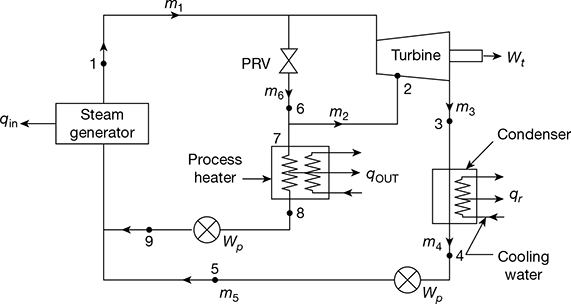
Figure 4.25 Combined power and heating cycle
When the power load is zero, all the steam passes through the pressure reducing valve (PRV) and none through the turbine. When heating load is zero, the steam expands through the turbine and flows into the condenser. In order to meet heating and power loads, the steam flow distribution is determined as follows:
The steam is extracted from the turbine at point 2 where the pressure is held constant by an automatic valve arrangement. The flow rate in the extraction line is computed from energy balance on the heating system as:
The power produced by this steam flowing through the turbine from the extraction point is,
W = m2 (h1 − h2)
Now h1 = h6 and h2 = h1 − w, so that h6 > h2.
The steam distribution to compute m2, m3 and m6 must satisfy the First Law of Thermodynamics for power required.
![]()
![]()
Example 4.11
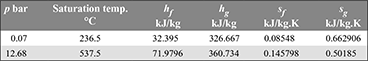
In a binary-vapour cycle, the steam cycle operates between 30 bar, 0.07 bar and uses a superheated temperature of 350°C. The mercury cycle works between 12.68 bar and 0.07 bar. The mercury vapour entering the turbine is in a dry saturated condition. Calculate the efficiency of the combined cycle assuming expansion in both cycles to be isentropic. Data for mercury is given below:
Solution
The binary vapour cycle is shown in Fig. 4.26.
Mercury cycle: sa = sb = sfb + xb (sgb − sfb)
0.50185 = 0.08548 + xb (0.662906 − 0.08548)
or xb = 0.721
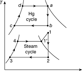
Figure 4.26 Binary vapour cycle neglecting pump work
= 32.395 + 0.721 (326.667 − 32.395) = 244.565 kJ/kg of Hg
Isentropic work done, wm = ha − hb = 360.734 − 244.565 = 116.169 kJ/kg Hg
Heat rejected, qrm = hb − hfb = 244.565 − 32.395 = 212.17 kJ/kg Hg
Heat supplied, qsm = ha − hfb = 360.734 − 32.395 = 328.339 kJ/kg Hg
Steam cycle: h1 = 3115.3 kJ/kg, s1 = 6.743 kJ/kg.K, h′1 = 2804.2 kJ/kg
or 6.743 = 0.5589 + x2 × 7.7179
or x2 = 0.80127
Work done, ws = h1 − h2 = 3115.3 − 2093.733 = 1021.567 kJ/kg
Heat supplied, qss = h1 = h1′ = 3115.3 − 2804.2 = 311.1 kJ/kg
Heat rejected by Hg/kg of steam = Heat received by water/kg steam
mm (hb − hfb) = 1 (h1′ − hf3)
or ![]()
Total work done per kg of steam,
w1 = ws + mm wm = 1021.567 + 12.447 × 116.161 = 2467.379 kJ/kg steam
Heat supplied in the cycle,
qs = mm qsm + qss = 12.447 × 328.339 + 311.1 = 4397.936 kJ/kg steam
Cycle efficiency = ![]()
Example 4.12
In a single-heater regenerative cycle, the steam enters the turbine at 32 bar, 350°C and the exhaust pressure is 0.12 bar. The feed water heater is a direct contact type which operates at 4.5 bar. Find (a) the efficiency and the steam rate of the cycle and (b) the increase in efficiency and steam rate as compared to Rankine cycle. Neglect pump work.
Solution
From steam tables, h1 = 3113.2 kJ/kg, s1 = 6.712 kJ/kg.K = s2 = s3
sg at 4.5 bar = 6.875 kJ/kg.K
The schematic diagram is shown in Fig. 4.27(a). The processes on the T-s and h-s diagrams are shown in Figs. 4.27(b) and (c) respectively. Since s2 < sg, state point 2 lies in the wet region.
sf2 = 1.821 kJ/kg.K, sfg2 = 5.036 kJ/kg.K
s1 = s2 = sf2 + x2 sfg2
or 6.712 = 1.821 + x2 × 5.036
or x2 = 0.9712
h2 = hf 2 + x2 hfg2 = 623.3 + 0.9712 × 2120.6 = 2682.83 kJ/kg

Figure 4.27 Single stage regenerative cycle: (a) Flow schematic diagram, (b) T-s diagram, (c) h-s diagram
sf3 = 0.6963 kJ/kg.K sfg3 = 7.3900 kJ/kg.K
s1 = s3 = sf3 + x3 sfg3
or 6.712 = 0.6963 + x2 × 7.3900
or x3 = 0.814
h3 = hf3 + x3 hfg3 = 206.92 ÷ 0.814 × 2384.1 = 2147.58 kJ/kg
Since wp = 0
∴ h4 = hf3 = 206.92 kJ/kg = h5
h6 = hf2 = 623.3 kJ/kg = h7
Energy balance for heater gives,
or m1 (2682.83 − 623.3) = (1 − m1) (623.3 − 206.92)
or 2059.53 m1 = (1 − m1) × 416.38
or m1 = 0.168 kg
wt = (h1 − h2) + (1 − m1) (h2 − h3)
= (3113.2 − 2682.83) + (1 − 0.168) (2628.83 − 2147.58) = 875.698 kJ/kg
qs = h1 − h6 = 3113.2 − 623.3 = 2489.9 kJ/kg
Steam rate = ![]()
Without regeneration, wt = h1 − h3 = 3113.2 − 2147.58 = 965.62 kJ/kg
Increase in cycle efficiency due to regeneration = 35.17 − 33.22 = 1.95%
Steam rate = ![]()
Increase in steam rate due to regeneration = 4.11 − 3.728 = 0.382 kg/kWh
Example 4.13
A steam power plant working on Rankine cycle is supplied with dry saturated steam at a pressure of 12 bar and exhausts into the condenser at 0.1 bar. Neglecting the pump work, calculate the cycle efficiency.
Solution
Corresponding to p = 12 bar, from steam tables we find that (see Fig. 4.3)
hf1 = 798.4 kJ/kg; hg1 = 1984.3 kJ/kg
s1 = sg1 = 6.519 kJ/kg°K
Corresponding to 0.1 bar, we find that
hf2 = 191.8 kJ/kg; hfg2 = 2393 kJ/kg
sf2 = 0.649 kJ/kg K; sfg2 = 7.502 kJ/kg·K
Process 1–2 is an isentropic expansion
s1 = s2
s1 = sg1 = 6.519 kJ/kg K
s2 = sf 2 + x2 sfg2
s2 = 0.649 + x2 × 7.502
6.519 = 0.649 + 7.502 x2
x3 = 0.783
h2 = hf2 + hfg2
=191.81 + 0.783 × 2392.8 = 2065.5 kJ/kg
h1 = hg2 = 2782.7 kJ/kg
Example 4.14
Dry saturated steam at 10 bar is supplied to a prime mover working on Rankine cycle and the exhaust takes place at 0.2 bar. Determine the cycle efficiency, efficiency ratio, and specific steam consumption of the prime mover, if the indicated thermal efficiency is 20%. Determine the percentage change in the cycle efficiency if the steam is initially 90% dry.
Solution
The h-s diagram is shown in Fig. 4.28.
From Mollier diagram (Fig. 4.28), we have
h1 = 2775 kJ/kg, h2 = 2150 kJ/kg
From steam tables,
hf2 = 251.5 kJ/kg corresponding to 0.2 bar
Thermal efficiency ![]()
Efficiency ratio = ![]()
Specific steam consumption = ![]()
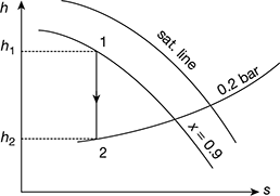
Percentage change in cycle efficiency if steam is initially 90% dry
From Mollier diagram, h1 = 2580 kJ/kg, h2 = 2030 kJ/kg (see Fig. 4.29)
Thermal efficiency ![]()
∴ Percentage change in Rankine efficiency =![]()
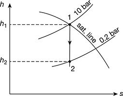
Figure 4.28 Mollier diagram for dry saturated steam
Example 4.15
The steam consumption of steam engine is 20 tonnes per shift of 8 hours when developing 220 kW. Dry and saturated steam enters the engine at 10 bar pressure and leaves at 0.1 bar pressure. Estimate the cycle efficiency and thermal efficiency of engine.
Solution
Given that ms = 20/8 tonne/h = 2.5 tonne/h = 2500 kg/h, P = 220 kW
The h-s diagrams is shown in Fig. 4.30.
From steam tables corresponding to 10 bar
h1 = hg1 = 2778.1 kJ/kg; s1 = sg1 = 6.5864 kJ/kg.K
and corresponding to 0.1 bar, we find that
hf2 = 191.81 kJ/kg; hfg2 = 2392.8 kJ/kg;
sf2 = 0.6492 kJ/kg.K; sg2 = 7.5010 kJ/kg.K
Since 1−2 is an isentropic process
s1 = s3
or 6.5864 = 0.6492 + x2 × 7.5010
or x2 = 0.791
∴ h3 = hf2 + x2 hfg2 = 191.81 + 0.791 × 2392.8 = 2084.5 kJ/kg
Cycle Efficiency (ηR) = ![]()
Thermal efficiency of engine;


Figure 4.30 Mollier diagram for dry saturated steam
Example 4.16
Steam at 50 bar, 400°C expands in a Rankine engine to 0.34 bar. For 150 kg/s of steam; determine (a) the power developed, (b) the thermal efficiency neglecting the pump work, and (c) the specific steam consumption.
Solution
The h-s diagrams is shown in Fig. 4.31.
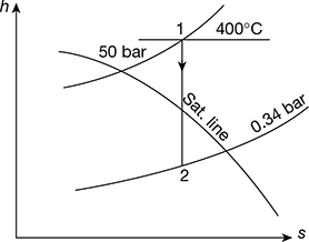
Figure 4.31 Mollier diagram for superheated steam
- Power developed = m(h1 − h2)
From Mollier diagram (Fig. 4.31), we have
h1 = 3198.3 kJ/kg, h2 = 2257.75 kJ/kg
hf2 = 301.5 kJ/kg (from steam tables)
Power developed = 150 [3198.3 − 2257.75] = 141082 kW
- Thermal efficiency
- Specific steam consumption =

Example 4.17
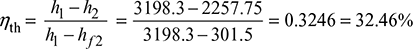
A steam engine is supplied with dry saturated steam at 15 bar. The pressure at release is 3 bar and the back pressure is 1 bar. Determine the efficiency of modified Rankine cycle.
Solution
Consider the Mollier diagram, as shown in Fig. 4.32.
From the Mollier diagram, we have
h1 = 2790 kJ/kg, h2 = 2510 kJ/kg, x2 = 0.9
From steam tables, corresponding to 3 bar, we have
vf2 =0.001073 m3/kg, vg2 = 0.6058 m3/kg
∴ Volume of steam at point 3,
v2 = vf2 + x2 (vg2 − vf2) = 0.001073 + 0.9 × (0.60585 − 0.001073) = 0.545 m3/kg

From steam tables corresponding to pressure of 1 bar, we find that sensible heat of water,
hf4 = 417.44 kJ/kg
ηMR = Thermal efficiency of modified Rankine cycle
Example 4.18
Steam at a pressure of 15 bar and 250°C is first expanded through a turbine to a pressure of 4 bar. It is then reheated at constant pressure to the initial temperature of 250°C and is finally expanded to 0.1 bar. Estimate the work done per kg of steam flowing through the turbine and the amount of heat supplied during the process of reheat.
Find the work output when there is direct expansion from 15 bar to 0.1 bar without any reheat. Assume all expansion processes to be isentropic.
Solution
Given that p1 = 15 bar; T1 = 250°C; p2 = 4 bar; T2 = 250°C; p3 = 0.1 bar
The reheating of steam is represented on the Mollier chart as shown in Fig. 4.33. From the chart, we find that,
h1 = 2930 kJ/kg; h2 = 2660 kJ/kg; h3 = 2965 kJ/kg; h4 = 2345 kJ/kg; and h5 = 2130 kJ/kg
From steam tables, corresponding to a pressure of 0.1 bar, we find that sensible heat of water at D,
hf4 = hf5 = 191.81 kJ/kg
Workdone per kg of steam:
We know that workdone per kg of steam,
w = (h1 − h2) + (h3 − h4)
= (2930 −2660) + (2965 − 2345) = 890 kJ/kg
Heat supplied during the process of reheat:
We know that the heat supplied during the process of reheat,
h = Heat supplied between 2 and 3
= (h3 − h2) − (hf4) = (2965 − 2660) − 191.81 = 113.2 kJ/kg

Work output when the expansion is direct:
The direct expansion from 15 bar to 0.1 bar is shown by the line AE in Fig. 4.33. We know that work output
= Total heat drop = h1 − h5 = 2930 − 2130 = 800 kJ/kg
Example 4.19
In a thermal plant, steam is supplied at a pressure of 30 bar and temperature of 300°C to the high pressure side of steam turbine where it is expanded to 5 bar. The steam is then removed and reheated to 300°C at a constant pressure. It is then expanded to the low pressure side of the turbine to 0.5 bar. Find the efficiency of the cycle with and without reheating.
Solution
Given that p1 = 30 bar; T1 = 300°C; p2 = 5 bar; T2 = 300°C; p3 = 0.5 bar
Efficiency of the cycle with reheating:
The reheating of steam is represented on the Mollier chart as shown in Fig. 4.34.
From the chart, we find that
h1 = 2990 kJ/kg; h2 = 2625 kJ/kg; h3 = 3075 kJ/kg; h4 = 2595 kJ/kg; and h5 = 2280 kJ/kg
From steam tables, corresponding to a pressure of 0.5 bar, we find that sensible heat of water at D,
hf4 = hf5 = 340.47 kJ/kg
Figure 4.34 Mollier diagram for superheated steam with reheating
We know that efficiency of the cycle with reheating,
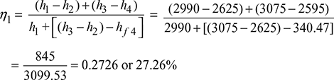
Efficiency of the cycle without reheating:
We know that efficiency of the cycle without reheating
Example 4.20
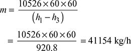
Steam supplied to a 10 MW turbo-alternator at 40 bar and 400°C. The auxiliaries consume 7% of the output. The condenser pressure is 0.05 bar and condensate is sub-cooled to 30°C. Assuming the boiler efficiency as 85%, the relative efficiency of turbine as 80%, and the mechanical efficiency of the alternator as 95%, determine (a) the steam consumption per hour, (b) the overall efficiency of the plant, and (c) the quality of steam at exit from turbine.
Solution
The h-s diagrams is shown in Fig. 4.35.
- From Mollier chart,
h1 = 3215 kJ/kg, h2 = 2064 kJ/kg
Therefore, (h1 − h2) = 3215 − 2064 = 1151 kJ/kg
Thus actual enthalpy drop,
(h1 − h2) = ηrelative × (h1 − h2)
= 0.8 × 1151 = 920.8 kJ/kg
Input to the alternator =
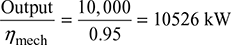

Figure 4.35 Mollier diagram for superheated steam
Therefore, steam consumption per hour,
- Heat supplied to the boiler/hour =
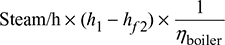

where hf2 = enthalpy of liquid at saturation at 0.05 bar from steam tables
The auxiliaries consume 7% of the output.
Therefore, useful output = (10,000 × 0.93) = 9300 kW = 9300 × 60 × 60 kJ/h
Thus overall efficiency =

- The dryness fraction at exit, that is, B′ is read at h2′ = 3215 − 920.8 = 2294.2 kJ on 0.05 bar line.
Thus, x2′ = 0.889
Example 4.21
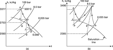
Two turbines, A and B, operate with steam at an initial pressure of 100 bar and temperature of 500°C. In each turbine, the steam is expanded in a high pressure turbine to 8.5 bar with efficiency ratio 80%. In turbine A, the expansion is further continued in low pressure turbine from 8.5 bar to 0.035 bar with efficiency ratio 0.75. In turbine B, steam is reheated after expansion in the high pressure turbine and is then fed to the low pressure unit at 7 bar and 500°C, after which it expands to 0.035 bar with efficiency ratio 0.85. Compare the two power cycle with respect to (a) thermal efficiency and (b) steam consumption for a full load output of 50,000 kW.
Solution
Turbine A: The expansion is shown on h-s chart in Fig. 4.36(a)
ha = 3377 kJ/kg and hb = 2753 kJ/kg
hc = hd = 3377 − 0.8 (3377−2753) = 2878 kJ/kg
he = 2060 kJ/kg
hf = hg = 2878 − (2878 − 2060) × 0.75 = 2264.5 kJ/kg
Total work done = (ha − hd) + (hd − hg) = (ha − hg)
Heat supplied = ha − hg
where hg is the sensible heat of steam at 0.035 bar = 110 kJ
∴ Heat supplied = 3377 − 110 = 3267 kJ
Thermal efficiency = ![]()
Total work to be done = 53,000 kW = 50,000 kJ/s
∴ Steam consumption = ![]()
Turbine B: The expansion is shown on h-s chart in Fig. 4.36(b)
ha = 3377 kJ/kg: hb = 2753 kJ/kg; hc = hd = 2878 kJ/kg
he = 3490 kJ/kg; hf = 2385 kJ/kg.
hh = 3490 − (3490 − 2315) 0.85 = 2551 kJ/kg
Total work done = (3377 − 2878) + (3490 − 2551) = 1438 kJ/kg
Total heat supplied = (3377 − 110) + (3490 − 2878) = 3879 kJ/kg.
∴ Thermal efficiency ![]()
Steam consumption = ![]()
Example 4.22
In a regenerative cycle, having one feed water heater, the dry saturated steam is supplied from the boiler at a pressure of 30 bar and the condenser pressure is 1 bar. The steam is bled at a pressure of 5 bar. Determine the amount of bled steam per kg of steam supplied and the efficiency of the cycle. What would be the efficiency without regenerative feed heating? Determine the percentage increase in efficiency due to regeneration.
Solution
Given that p1 = 30 bar; p3 = 1 bar; p2 = 5 bar
From Mollier diagram, as shown in Fig. 4.37, we find that
Enthalpy of steam at 30 bar, h1 = 2800 kJ/kg
Enthalpy of steam at 5 bar, h2 = 2460 kJ/kg
Enthalpy of steam at 1 bar, h3 = 2220 kJ/kg
From steam tables, we also find the enthalpy or sensible heat of water at 5 bar.
hf2 = 640.21 kJ/kg
and enthalpy or sensible heat of water at 1 bar,
hf3 = 417.44 kJ/kg
Amount of bled steam per kg steam supplied
We know that amount of bled steam per kg of steam supplied,
Efficiency of the cycle: We know that efficiency of the cycle,

Efficiency of the cycle without regenerative feed heating: We know that efficiency of the cycle,

Percentage increase in efficiency due to regeneration: We know that percentage increase in efficiency due to regeneration
Example 4.23
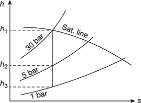
In a steam turbine plant, the steam is generated and supplied to the turbine at 50 bar and 370°C. The condenser pressure is 0.1 bar and the steam enters the condenser with dryness fraction of 0.9. Two feed water heaters are used, the steam in the heaters being bled at 5 bar and 0.5 bar. In each heater, the feed water is heated to saturation temperature of the bled steam. The condensate is also pumped at this temperature into the feed line immediately after the heater. Find the masses of the steam bled in the turbine per one kg of steam entering the turbine. Assuming the condition line for the turbine to be straight, calculate the thermal efficiency of the cycle.
Solution
Given that p1 = 50 bar; T1 = 370°C; p4 = 0.1 bar; x4 = 0.9; p2 = 5 bar; p3 = 0.5 bar
First, let us draw the Mollier diagram and condition line for the cycle, as shown in Fig. 4.38. From this diagram, we find that,
h1 = 3110 kJ/kg, h2 = 2780 kJ/kg, h3 = 2510 kJ/kg, h4 = 2350 kJ/kg
From steam tables, we also find that
hf2 = 640.21 kJ/kg (at 5 bar)
hf3 = 340.47 kJ/kg (at 0.5 bar)
hf 4 = 191.81 kJ/kg (at 0.1 bar)
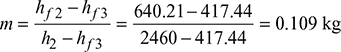
Mass of steam bled in the turbine:
We know that mass of steam bled at 2.

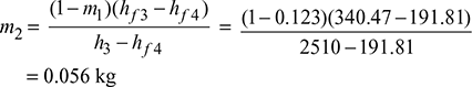
and mass of steam bled at 3.
Thermal efficiency of the cycle:
We know that work done from 1 to 2 per kg of feed water
= h1 − h2 = 3110 − 2780 = 330 kJ/kg
Similarly, work done from 2 to 3 per kg of feed water
= (1 − m1)(h2 − h3) = (1 − 0.123) (2780 − 2510) kJ/kg
= 236.8 kJ/kg
and work done from 3 to 4 per kg of feed water
= (1 − m1 − m2) (h3 − h4) = (1 − 0.123 − 0.056) (2510 − 2350) kJ/kg
= 131.4 kJ/kg
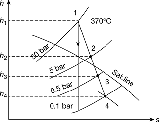
Figure 4.38 Mollier diagram
∴ Total work done = 330 + 236.8 + 131.4 = 698.2 kJ/kg
Heat supplied = h1 − hf2 = 3110 − 640.1 = 2469.9 kJ/kg
∴ Thermal efficiency of cycle,
Example 4.24
In the Rankine cycle, steam leaves the boiler and enters the turbine at 4 MPa and 400°C. The condenser pressure is 10 kPa. Neglecting pump work, determine the cycle efficiency and the Carnot efficiency for the same temperature limits.
Solution
Refer to Fig. 4.39. Rankine cycle is represented by 1−2−3−4 ignoring pump work, Carnot cycle for the same temperature limits may be reproduced by 1−2′−3′−4′.
Carnot efficiency is given by
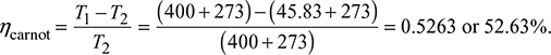
(It may be noted that Carnot efficiency is independent of the working substance.)
From steam tables, h1 at 4MPa and 400°C = 3213.5 kJ/kg, s1 = 6.7689 kJ/kg.K
At 10 kPa
hf = 191.81 kJ/kg, hfg = 2392.8 kJ/kg, sf = 0.6492 kJ/kg.K, sfg = 7.5010 kJ/kg.K
Also s1 = s2
or 6.7689 = 0.6492 + x2 × 7.5010
or ![]()
∴ h2 = hf3 + x2hfg = 191.81 + 0.816 × 2392.8 = 2144.33 kJ/kg
Thermal efficiency ηRankine =![]()
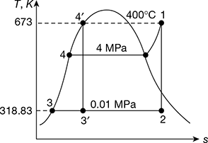
Figure 4.39 T-s diagram for Rankine cycle
Example 4.25
A steam power plant has the range of operation from 40 bar dry saturated to 0.05 bar. Determine (a) the cycle efficiency and (b) the work ratio and specific fuel consumption for (i) Carnot cycle and (ii) Rankine cycle.
Solution
From steam tables:
At 40 bar, tg = 250.4°C, vf = 0.001252 m3/kg, vg = 0.049778 m3/kg, hf = 1087.29 kJ/kg, hg = 2801.40 kJ/kg, sg = 6.07 kJ/kg.K
At 0.05 bar, tg = 32.88°C, vf = 0.0010005 m3/kg, vg = 28.193 m3/kg, hf = 137.79 kJ/kg
hfg = 2423.7 kJ/kg, sf = 0.4763 kJ/kg.K, sfg = 7.9187 kJ/kg.K
- Refer of Fig. 4.40. for Carnot cycle analysis on T-s plane.
Cycle efficiency =
(Note: Processes 1−2 and 3−4 are reversible adiabatic.)
Also s1 = s2 = sf + x2sfg
or
Also s4 = s3 = sf + x3sfg
or

Figure 4.40 Carnot cycle on T-s plot
∴ h2 = 137.79 + 0.706 × 2423.7 = 1848.9 kJ/kg.
and h3 = 137.79 + 0.293 × 2423.7 = 847.9 kJ/kg.
∴ ηCarnot cycle =


Alternatively,

- Refer to Fig. 4.41 for Rankine cycle analysis
Pump work = hM − hf3
= 0.001005 × 39.95 × 102 = 4.015 kJ/kg
Therefore, net work
wnet = h1 − h2 − wpump = 2801.4 − 1848.9 − 4.015 = 948.485 kJ/kg
and ηRankine cycle =
 = 0.3566 or 35.66%

- b. Also work ratio =

Specific steam consumption/kWh

Example 4.26
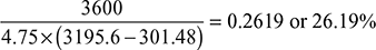
Steam at 50 bar, 400°C expands in a steam tubine to 0.34 bar. For 150 kg/s of steam; determine (a) the power developed, (b) the thermal efficiency, and (c) the specific steam consumoption (i) for the Rankine cycle and (ii) for the Rankine engine. For an actual engine with same specifications, the brake steam rate is 4.75 kg/kWh and the driven electric generator has an electro mechanical efficiency of 94%.
Determine (a) the brake thermal efficiency, (b) the internal efficiency (expansion efficiency), (c) the power in kW, and (d) the exhaust dryness fraction of steam.
Solution
Refer to Fig. 4.42.
At 50 bar and 400°C
h1 = 3195.6 kJ/kg, s1 = 6.6458 kJ/kg.K, v1 = 0.05781 m3/kg
At 0.34 bar, hf = 301.48 kJ/kg, hfg = 2328.9 kJ/kg, sf = 0.9795 kJ/kg.K, sfg =6.7471 kJ/kg.K
And s1 = s2 for ideal expansion
6.6458 = 0.9795 + x2 ×6.7471
or x2 = 0.84
Thus h2 = hf3 + x2hfg = 301.43 + 0.84 × 2328.9 = 2257.756 kJ/kg
- For cycle wpump = Pump work = hM − hf3

- For engine
- Power developed = Steam per sec × (h1 − h2) = 150 × (3195.6 − 2257.756)
= 140676.6 kW
- ηRankine engine =

- Steam rate or specific steam consumption

- Power developed = Steam per sec × (h1 − h2) = 150 × (3195.6 − 2257.756)
- Actual engine
Brake specific steam consumption = 4.75 kg/kWh
ηbrake thermal =
Expansion efficiency =

Actual enthalpy drop = 0.808 × Isentropic enthalpy drop
= 0.808 (3195.6 − 2257.756) = 757.8 kJ/kg
Thus, h′2 = h1 − 757.8 = 3195.6 − 757.8 = 2437.8 kJ/kg
Also, h′2 = hf2 + xhfg2
Thus,


Example 4.27
In a steam power plant operating on Rankine cycle, the steam enters the turbine at 70 bar and 550°C with a velocity of 30 m/s. It discharges to the condenser at 0.20 bar with a velocity of 90 m/s. If the steam flow rate is 35 kg/s find the thermal efficiency and the net power produced. Neglect pump work.
[IES, 1992]
Solution
Given that p1 = 70 bar, t1 = 550°C, c1 = 30 m/s, p2 = 0.20 bar, c2 = 90 m/s, ṁs = 35 kg/s
The simple Rankine cycle is shown in Fig. 4.43(a) and T-s diagram in Fig. 4.43(b).
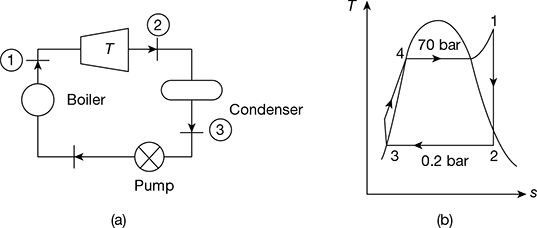
Figure 4.43 Rankine cycle: (a) Schematic diagram, (b) T-s diagram
At p1 = 70 bar and t1 = 550°C, h1 = 3530.9 kJ/kg, s1 = 6.9486 kJ/kg.K
At p2 = 0.2 bar, hf2 = 251384 kJ/kg, hfg2 = 2358.3 kJ/kg, sf2 = 0.8319 kJ/kg.K, sfg2 = 7.0766 kJ/kg.K
Now s1 = s2 = sf2 + x2 sfg2
or 6.9486 = 0.8319 + x2 × 7.0766
or x2 = 0.8644
∴ h2 = hf2 + x2 hfg2
= 251.38 + 0.8644 × 2358.3 = 2289.89 kJ/kg
Net power produced = ṁs (h1 − h2) = 35 (3530.9 − 2289.89) = 43435.35 kW
Thermal efficiency, ![]()
Now hf3 = hf2
Example 4.28
The following data refer to a steam turbine power plant employing one stage of regenerative feed heating:
State of steam entering HP stage: 10 MPa, 600°C
State of steam entering LP stage: 2 MPa, 400°C
State of steam at condenser : 0.01 MPa, x = 0.9
The correct amount of steam is bled for feed heating at exit the HP stage. Calculate the mass of steam bled per kg of steam passing through the HP stage and the amount of heat supplied in the boiler per second for an output of 10 MW. Neglect pump work.
[IES, 1993]
Solution
The schematic diagram and T-s diagram are shown in Fig.4.44(a) and (b).
H.P. stage: p1 = 10 MPa, t1 = 600°C
L.P. stage: p2 = 2 MPa, t2 = 400°C
Condenser: p3 = 0.01 MPa, x3 = 0.9
Wout = 10 MW
From steam tables, we have (Fig. 4.44(a))
h1 = 3625.3 kJ/kg
h2 = 3247.6 kJ/kg
h3 = hf3 + x3 hfg3
= 191.81 + 0.9 × 2392.8 = 2345.35 kJ/kg
Heat balance for the heater:
(1 − m1) (h5 − h4) = m1(h2 − h5)
From steam tables,
h5 = 908.77 kJ/kg at p2 = 2 MPa
h4 = 191.81 kJ/kg at p3 = 0.01 MPa
∴ (1 − m1)(908.77 − 191.81) = m1(3247.6 − 908.77)
or (1 − m1) × 716.96 = 2338.83 m1

or ![]()
Heat supplied in boiler,
qin = h1 − h5 = 3625.3 − 908.8 = 2716.5 kJ/kg
Work output from boiler,
Wout = (h1 − h2) + (1 − m1) (h2 − h3)
= (3625.3 − 3247.6) + (1 − 0.235) (3247.6 − 2345.35) = 1067.92 kJ/kg
Cycle efficiency, ![]()
Heat supplied in the boiler for 10 MW output =![]()
Example 4.29
A small power plant produces 25 kg/s steam at 3 MPa, 600°C in the boiler. It cools the condenser with ocean water coming in at 12°C and returned at 15°C. Condenser exit is 45°C. Find (a) the net power output and (b) the required mass flow rate of ocean water.
[IAS 2012]
Solution
Given that ṁs= 25 kg/s, p1 = 3 MPa, t1 = 600°C, twi = 12°C, two = 15°C, T1 = 600 + 273 = 873 K,T2 = 45 + 273 = 318 K
The T-s diagram is shown in Fig. 4.45.
- h1 = 3682 kJ/kg, hf3 = 188.4 kJ/kg, p1 = 9.5934 kPa, s1 = 7.5084 kJ/kg.K
vf3 = 0.00101 m3/kg, hfg3 = 2394.8 kJ/kg
sf3 = 0.6386 kJ/kg.K, sfg3 = 7.5261 kJ/kg.K
Now s1 = s2 = sf3 + x2 sfg3
or 7.5084 = 0.6386 + x2 × 7.5261
or x2 = 0.9128
h2 = hf3 + x2 hfg3 = 188.42 + 0.9128 × 2394.8 = 2374.39 kJ/kg
Pump work, wp = vf3 (p1 − p2) = 0.00101 (300 − 9.59) = 0.29 kJ/kg
Turbine work, wt = h1 − h2 = 3682.3 − 2374.39 = 1307.91 kJ/kg
Net work, wnet = wt − wp = 1307.91 − 0.29 = 1307.62 kJ/kg
Net power output = ṁs × wnet = 25 × 1307.62 = 32.69 MW
- Heat rejected constant pressure p2, qr = h2 − hf3 = 2374.39 − 188.42 = 2185.97 kJ/kg
Let ṁw = mass of ocean water circulated
ṁwcpw × Δtw = ṁs× qror ṁw × 4.187 × (15 − 12) = 25 × 2185.97
or ṁw = 4350.7 kg/s

Summary for Quick Revision
- The Rankine cycle is a vapour pressure cycle which operates on steam and is used for steam power plant. It consists of a boiler, turbine, condenser, and a pump.
- Net work, wnet = qa − qr= (h1 − hfM) − (h2 − hf 3) = (h1 − h2) − wp = wt − wp
Pump work, wp = hfM − hf3 = vf 3 (pM − p3) × 102 kJ/kg
= vf 3 (p1 − p3) × 102 kJ/kg [∵ pM = p1]
where vf is in m3/kg and p is in bar.
- Thermal efficiency of Rankine cycle considering pump work,
Heat rate =

- Thermal efficiency of Rankine cycle neglecting pump work,

- Specific steam consumption,
- Overall heat rate, OHR = SSC × heat supplied per kg of throttle steam

- Back work ratio,
 and work ratio,
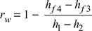
- Increase of boiler pressure leads to increase in thermal efficiency of ideal Rankine cycle.
- Decrease in condenser pressure leads to increase in thermal efficiency of ideal Rankine cycle.
- Thermal efficiency of Rankine cycle can be improved by reheating and regeneration.
- Efficiency of reheat cycle, ηreheat=

- In the reheat cycle, steam is extracted at a suitable point after expanding in high pressure turbine and is reheated with the help of fl ue gases in the boiler furnace.
- Regeneration is a method to heat the feed water from the hot well of condenser reversibly by interchange of heat with the system to improve the cycle efficiency
- In open heaters, the bled steam is allowed to mix with feed water.
- In closed heaters, the bled steam is not allowed to mix with feed water. The feed water fl ows through the tubes in the heater and bled steam condenses on the outside of tubes.
- In a binary vapour cycle, two cycles with diff erent working fl uids are coupled in a series. Mercury is used in the topping cycle and steam in the bottoming cycle.
- In co-generation, some part of the expanded steam in the HP turbine is bled to generate electric power.
Multiple-choice Questions
- The efficiency of Rankine cycle can be increased by
- decreasing initial steam pressure and temperature
- increasing exhaust pressure
- increasing expansion ratio
- increasing regenerative heaters
- Choose the wrong statement:
- bleeding increases the thermodynamic efficiency of turbine
- bleeding increases the net power developed by turbine
- bleeding decreases the net power developed by turbine
- boiler is supplied with hot water due to bleeding.
- In the Rankine cycle, with the maximum steam temperature being fixed from metallurgical consideration, as the boiler pressure increases,
- the condenser load will increase
- the quality of turbine exhaust will decrease
- the quality of turbine exhaust will increase
- the quality of turbine exhaust will remain unchanged
- Rankine cycle comprises
- Regeneration effect on Rankine cycle
- decreases thermal efficiency
- increases thermal efficiency
- has no effect on thermal efficiency
- increases or decreases thermal efficiency depending on the point extraction of steam.
- Superheating of steam before expansion in a Rankine cycle
- decreases thermal efficiency
- has no effect on thermal efficiency
- increases thermal efficiency
- may increase or decrease thermal efficiency.
- Reheating of steam
- increases thermal efficiency
- increases work output of turbine
- decreases work output of turbine
- increases thermal efficiency but decreases work output.
- In a binary vapour cycle,
- mercury is used in the bottoming cycle
- steam is used in the topping cycle
- mercury is used in the topping cycle
- either mercury or steam may be used in the topping cycle.
- In a steam power plant, feed water heater is a heat exchanger to preheat feed water by
- live steam from steam generator
- hot flue gases coming out of the boiler furnace
- hot air from air preheater
- extracting steam from turbine
- Consider the following statements regarding effects of reheating of steam in a steam turbine:
- It increases the specific output of the turbine.
- It decreases cycle efficiency.
- It increases blade erosion.
- It improves the quality of exit steam.
Which of these statements are correct?
- I and II
- II and III
- III and IV
- I and IV
- In a steam power plant, what is the outcome of regenerative feed water heating?
- Increase in specific output
- Increase in cycle efficiency
- Improved quality of exhaust steam
- Reduced condenser load
Select the correct answer using the code given below:
- I and III only
- II only
- II and IV
- I, II and III
- In a regenerative feed heating cycle, the economic number of the stages of regeneration
- increases as the initial pressure and temperature increase
- decreases as the initial pressure and temperature increase
- is independent of the intitial pressure and temperature
- depends only on the condenser pressure
- Consider the following statements:
The reheat cycle helps to reduce
- fuel consumption
- steam flow
- the condenser size
Which of these statements are correct?
- I and II
- I and III
- II and III
- I, II, and III
- The main advantage of a reheat Rankine cycle is
- reduced moisture content in LP side of turbine
- increased efficiency
- reduced load on condenser
- reduced load on pump
- Consider the following statement pertaining to the features of regenerative steam cycle plant as compared to a non-regenerative plant:
- It increases the cycle efficiency.
- It requires a bigger boiler.
- It requires a smaller condenser.
Which of the statements are correct?
- I, II, and III
- I and II
- II and III
- I and III
- Which of the following statements is not correct for regenerative steam cycle?
- Consider the following for a steam turbine power plant:
- Reduction in blade erosion
- Increase in turbine speed
- Increase in specific output
- Increase in cycle efficiency
Which of these occurs due to reheating of steam?
- Only I
- I and II
- I, III, and IV
- II and III
- When is the greatest economy obtained in a regenerative feed heating cycle?
- Steam is extracted from only one suitable point of a steam turbine.
- Steam is extracted only from the last stage of steam turbine.
- Steam is extracted only from the first stage of a steam turbine.
- Steam is extracted from several places in different stages of steam turbines.
- Consider the following statements:
The purpose of reheating the steam in a steam turbine power plant is to
- increase specific output
- increase turbine efficiency
- reduce turbine speed
- reduce specific steam consumption
Which of the statements are correct?
- II and IV
- I and III
- I, II, and IV
- I, III, and IV
- In the bottoming cycle of cogeneration, low-grade waste heat is used for
- processing
- power generation
- feed water heating
- None of these
- In steam and other vapour cycles, the process of removing non-condensables is called
- scavenging process
- deaeration process
- exhaust process
- condensation process
Review Questions
- Draw the T-s diagram for a simple Rankine cycle and write down the expression for its efficiency.
- What is the eff ect of boiler pressure and condenser pressure on Rankine cycle efficiency?
- What are the various methods of improving thermal efficiency of Rankine cycle?
- Draw the reheat Rankine cycle with superheated steam and write down the expression for its efficiency.
- Explain regeneration. What are its advantages?
- What is the diff erence between open heater and closed heater?
- What are the properties of an ideal working fl uid for the Rankine cycle?
- What is a binary vapour cycle?
- What is co-generation?
- List the advantages of co-generation.
- What is the diff erence between bleeding and extraction of steam?
Exercises
4.1 A simple Rankine cycle works between 30 bar and 0.04 bar pressures, the initial condition of steam being dry saturated. Caculate the cycle efficiency, work ratio, and specific steam consumption.
[Ans. 35%, 0.997, 3.84 kg/kWh]
4.2 In a Rankine cycle, the steam at inlet to turbine is saturated at pressure of 30 bar and the exhaust pressure is 0.25 bar. Calculate (a) the pump work, (b) the turbine work, (c) the cycle efficiency, and (d) the condenser heat fl ow per kg of steam.
[Ans. 3 kJ, 741 kJ, 29.2%, 1790 kJ]
4.3 Steam at 90 bar, 480°C is supplied to a steam turbine. The steam is reheated to its original temperature by passing the steam through a reheater at 12 bar. The expansion after reheating takes place to condenser pressure of 0.07 bar. Calculate the efficiency of the reheat cycle and work output per kg of steam.
[Ans. 42.2%, 1611 kJ/kg]
4.4 A reheat cycle operating between 30 bar and 0.04 bar has a superheat and reheat temperature of 450°C. The first expansion takes place till the steam is dry saturated and then reheat is given. Determine the ideal cycle efficiency neglecting feed pump work.
[Ans. 38.7%]
4.5 In a regenerative cycle, the steam pressure at turbine inlet is 30 bar and the exhaust is at 0.04 bar. The steam is initially saturated. Enough steam is bled off at the optimum pressure to heat the feed water. Neglecting pump work, determine the cycle efficiency.
[Ans. 37.3%]
4.6 Steam is supplied to a turbine at pressure of 32 bar, 420°C. It expands isentropically to a pressure of 0.08 bar. Determine the thermal efficiency of the cycle.
If the steam is reheated at 6 bar to 400°C and then expanded isentropically to 0.08 bar, then find the thermal efficiency.
[Ans. 35.4%, 36.6%]
4.7 Steam of 28 bar and 50°C superheat is passed through a turbine and expanded to a pressure where the steam is dry saturated. It is then reheated at constant pressure to its original temperature and then expanded to the condenser pressure of 0.2 bar, the expansion being isentropic. Calculate work done per kg of steam and thermal efficiency with and without reheat.
[Ans. 810 kJ/kg, 880 kJ/kg, 30%, 30.3%]
4.8 In a binary vapour cycle, the pressure in the mercury boiler is 15.4 bar and in the mercury condenser is 0.2 bar. The pressure limits for steam cycle are 54 bar and 0.08 bar. If both mercury and steam enter their respective turbines in a dry saturated state, find mass of mercury in kg per kg of steam and thermal efficiency of the cycle.
[Ans. 11.4 kg, 57.61%]
4.9 A binary vapour cycle consists of a mercury operating between 14 bar and 0.1 bar and steam cycle operating between 30 bar, 450°C and 0.04 bar. Calculate the ideal cycle efficiency of the cycle.
[Ans. 51.78%]
4.10 Steam is supplied to a regenerative cycle as dry and saturated at 32 bar the condenser pressure is 0.05 bar. If steam is bled at 2.8 bar, find the quality of steam bled, the cycle efficiency, and the specific steam consumption.
[Ans. 0.718, 35.27%, 4.342 kg/kWh]
ANSWERS TO MULTIPLE-CHOICE QUESTIONS
- a
- c
- c
- b
- b
- c
- b
- c
- d
- d
- c
- a
- a
- a
- d
- b
- d
- c
- c
- b
- b