
Chapter 18
Introduction to Refrigeration
18.1 ❐ INTRODUCTION
The process of producing cold by artificial means may be called refrigeration. The term ‘refrigeration’ may be defined as the artificial withdrawal of heat, producing in a substance or within a space, a temperature lower than that which would exist under the natural influence of surroundings. In other words, the refrigeration means a continued extraction of heat from a body whose temperature is already below the temperature of its surroundings. In refrigeration, heat is virtually being pumped from a lower temperature to a higher temperature.
According to the second law of thermodynamics, the extraction of heat from a body at lower temperature to a higher temperature can only be performed with the aid of some external device. Such a device is called refrigerator. A refrigerator is a reversed heat engine or a heat pump which extracts heat from a cold body and delivers it to a hot body. The substance or medium which works in a heat pump to extract heat from a cold body and to deliver to a hot body is called a refrigerant.
18.2 ❐ REFRIGERATION SYSTEMS
A refrigeration system is a device to produce the refrigeration effect. Some of the popular refrigeration systems are:
- Ice refrigeration-used in hotels for keeping the drinks cold.
- Evaporative refrigeration-desert bag, artificial snow.
- Air refrigeration-aircrafts.
- Gas throttling refrigeration-liquefaction of gases, like air, nitrogen and oxygen.
- Vapour compression refrigeration-domestic refrigerator.
- Vapour absorption refrigeration-ice making using aqua ammonia or water plus lithium bromide as the absorbent.
- Steam jet refrigeration-comfort cooling in air-conditioning installations or in industrial processes.
- Liquid gases refrigeration-transportation vehicles for perishable items.
- Dry ice (solid CO2) refrigeration-transportation of perishable items.
18.3 ❐ METHODS OF REFRIGERATION
The methods of refrigeration are:
- Vapour compression refrigeration.
- Vapour absorption refrigeration.
- Ejector-compression refrigeration.
- Electro-Lux refrigeration.
- Solar refrigeration.
- Thermo-electric refrigeration.
- Vortex-tube refrigeration.
18.3.1 Vapour Compression Refrigeration System
The schematic diagram of simple vapour compression refrigeration system is shown in Fig. 18.1.
It consists of the following five essential parts:
- Compressor: The low pressure and temperature vapour refrigerant from evaporator is drawn into the compressor through the inlet or suction valve A, where it is compressed to a high pressure and temperature. This high pressure and temperature vapour refrigerant is discharged into the condenser though the delivery, or discharge valve B.
- Condenser: The condenser or cooler consists of coils of pipe in which the high pressure and temperature vapour refrigerant is cooled and condensed. The refrigerant, while passing through the condenser, gives up its latent heat to the surrounding condensing medium which is normally air or water.
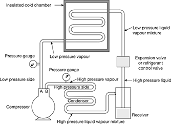
Figure 18.1 Simple vapour compression refrigeration system
- Receiver: The condensed liquid refrigerant from the condenser is stored in a vessel known as receiver from where it is supplied to the evaporator through the expansion valve or refrigerant control valve.
- Expansion valve: It is also called throttle valve or refrigerant control valve. The function of the expansion valve is to allow the liquid refrigerant under high pressure and temperature to pass at a controlled rate after reducing its pressure and temperature. Some of the liquid refrigerant evaporates as it passes through the expansion valve, but the greater portion is vapourised in the evaporator at the low pressure and temperature.
- Evaporator: An evaporator consists of coils of pipe in which the liquid vapour refrigerant at low pressure and temperature is evaporated and changed into vapour refrigerant at low pressure and temperature. In evaporating, the liquid vapour refrigerant absorbs its latent heat of vaporisation from the medium (air, water or brine) which is to be cooled.
Note: In any compression refrigeration system, there are two different pressure conditions. One is called the high pressure side and other is known as low pressure side. The high pressure side includes the discharge line (i.e. piping from delivery valve B to the condenser), condenser, receiver and expansion valve. The low pressure side includes the evaporator, piping from the expansion valve to the evaporator and the suction line (i.e. piping form the evaporator to the suction valve A).
18.3.2 Vapour Absorption System
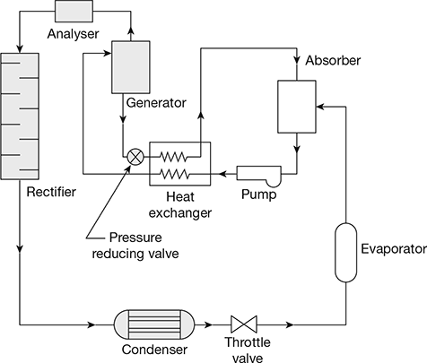
A simple vapour absorption system consists of a condenser, an expansion device, an evaporator, an absorber, a pump, a generator and a pressure reducing valve. The system can be improved by incorporating a regenerative heat exchanger between the poor and rich solutions. The two commonly used refrigerant absorbent pairs are ammonia-water (aqua ammonia) and lithium bromide-water. Lithium bromide-water system is superior to ammonia water system. In aqua ammonia, ammonia works as the refrigerant and water as the absorber, whereas in the other pair, water acts as the refrigerant and lithium bromide as the absorber.
A schematic diagram of absorption refrigeration system is shown in Fig. 18.2. The working of the ammonia absorption system is described below:
Ammonia vapour is produced in the generator at high pressure from aqua ammonia by external heating. The water vapour are removed by passing through an analyser and rectifier. The dehydrated ammonia enters the condenser where vapours are condensed. The sub-cooled high pressure liquid ammonia is passed through a throttle valve to further lower its temperature. Now they enter the evaporator and leave as saturated vapour. The saturated vapour goes to absorber to become strong after absorbing ammonia vapour and the strong solution is pumped to the generator through the pump and heat exchanger. The solution in the generator becomes weak as ammonia vapour comes out of it. The weak ammonia solution from the generator is passed to the heat exchanger through the pressure reducing valve. The cycle is repeated.
18.3.3 Ejector-Compression System
The system using water as the refrigerant in a vapour compression cycle in which compression is achieved by the principle of jet compression employing its own vapour as the motive vapour is called steam-ejector system. Refrigeration effect is obtained by direct evaporation and subsequent self cooling of water.
Bubble point temperature is the temperature at which a liquid mixture begins to boil. Azeotrope is a constant temperature boiling mixture.
18.3.4 Electro-Lux Refrigeration
This vapour absorption system uses ammonia as the refrigerant and hydrogen as the inert gas medium. The inert gas is confined only to the low side of the system, i.e., evaporator and absorber. In the evaporator, ammonia evaporates in the presence of hydrogen atmosphere. The partial pressure of ammonia is much lower than its pressure and thus give very low temperature. Hydrogen has the advantage of being non-corrosive and insoluble in water. This system is used for domestic refrigeration.
18.3.5 Solar Refrigeration
This uses the strong aqua ammonia vapour absorption system by utilizing the solar energy as the heat source to produce the refrigeration effect. This is an intermittent cycle. Lithium chloride-water system has also been used.
18.3.6 Thermo-electric Refrigeration
It is based on the thermoelectric effects: Seebeck effect, Peltier effect, and the Thomson effect. These effects are reversible in nature. The other two irreversible effects associated with thermoelectricity are the energy. Joule effect and conduction effect. It has low COP but infinite life expectancy, no leakage problem.
18.3.7 Vortex Tube Refrigeration
Vortex tube is a simple device for producing cold. It consists of a nozzle, diaphragm, valve, hot air side and cold air side. This is the only device to produce the refrigeration effect by utilizing the waste heat energy.
18.4 ❐ UNIT OF REFRIGERATION
The capacity of a refrigeration unit is given in tons of refrigeration. A ton of refrigeration is defined as the quantity of heat to be removed in order to form one ton of ice in 24 hours when the initial temperature of water is 0°C. 1 ton of refrigeration, TR = 211 kJ/min or 3.5167 kW. Taking latent heat of freezing of water equal to 336 kJ/kg, we have
Coefficient of performance (COP): The COP of a refrigeration system is a ratio of the heat removed (cooling effect produced) from a system to the work supplied to achieve the heat removal.
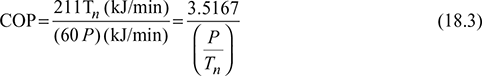
where P = energy required in kW
Tn = capacity of plant in tons
18.5 ❐ REFRIGERATION EFFECT
During evaporation, the liquid-vapour refrigerant absorbs its latent heat of vapourisation from the medium (air, water, brine) which is to be cooled. This heat which is absorbed by the refrigerant is called the refrigeration effect. In other words, the refrigeration effect is the amount of cooling produced.
18.6 ❐ CARNOT REFRIGERATION CYCLE
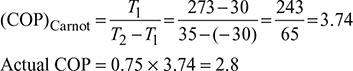
The reversed Carnot cycle is shown in Fig. 18.3 on p-v and T-s. diagrams. The sequence of operations is given below:
- The process 1-2 represents the isentropic compression of the working fluid with the aid of external work. The temperature of the working fluid rises from T1 to T2.
- The process 2-3 represents the isothermal compression of the working fluid during which heat Qr is rejected at constant high temperature T2.
- The process 3-4 represents the isentropic expansion of the working fluid. The temperature of working fluid drops from T2 to T1.
- The process 4-1 represents the absorption of heat Qa by the working fluid from refrigerator at constant low temperature T1 during isothermal expansion.
The Carnot cycle is practically not feasible since isothermal energy rejection requires extremely slow motion followed by isentropic process during which the piston should move at extremely faster rate, which is mechanically not obtainable.
The COP of reversed Carnot cycle is the highest of all refrigeration cycles. COP increases as T1 is increased or T2 is lowered. The increase in COP for increased T1is more than for decreased T2. Since T2 in winter is less than T2 in summer therefore COP in winter is more than that of in summer.
If the cycle is used as a heat pump, then energy performance ratio,

Figure 18.3 Reversed Carnot cycle: (a) p-v diagram, (b) T-s diagram
18.7 ❐ DIFFERENCE BETWEEN A HEAT ENGINE, REFRIGERATOR AND HEAT PUMP
Heat Engine: In a heat engine, as shown in Fig. 18.4(a), the heat supplied to the engine is converted into useful work. If Q2 is the heat supplied to the engine and Q1 is the heat rejected from the engine, then the net work done by the engine is given by,
Efficiency of heat engine,
Refrigerator: A refrigerator is an equipment used to remove the heat continuously from the space (sink). It maintains the temperature below atmospheric temperature and reject the heat to the atmosphere (source) by increasing the temperature potential of the heat to be rejected with the help of mechanical work input (compressor).
The refrigeration system is shown in Fig. 18.4(b). In a refrigerator system Q1 quantity of heat is removed from the source where its temperature T1 is maintained below atmospheric temperature T2. COP of refrigerator is,
Heat Pump: It is an equipment used to supply the heat continuously to the space. It maintains the temperature above atmospheric temperature by absorbing the heat from the atmosphere and increasing its temperature potential with mechanical work input (compressor). The heat pump system is shown in Fig. 18.4(c). In a heat pump system, Q2 quantity of heat is supplied to the room where the temperature T2 is maintained above atmospheric temperature T1. The heat Q1 is obtained from the atmosphere.

Figure 18.4 (a) Heat engine, T1> T>atm, (b) Refridgerator T1 < Tatm, (c) Heat pump
COP or Energy performance ratio of heat pump is,

Example 18.1
Find the COP of a refrigeration system if the work input is 10 kJ/kg and refrigeration effect produced is 180 kJ/kg of refrigerant flowing.
Solution
Example 18.2
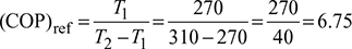
A machine working on a Carnot cycle operates between 310 K and 270 K. Calculate the COP when it is operated as:
- a refrigerator, and
- a heat pump.
Solution
Given: T1 = 270 K, T2 = 310 K
- Refrigerator
- Heat pump:

Example 18.3
A Carnot refrigeration cycle absorbs heat at 268 K and rejects it at 298 K.
- Calculate the COP of this refrigeration cycle.
- If the cycle is absorbing 1150 kJ/min at 268 K, find the rate of work input required.
- How many kJ/s will be delivered if it works as a heat pump at 298 K and absorbs 1150 kJ/min at 268 K.
Given: T1 = 268 K, T2 = 298 K, Q1 = 1150 kJ/min
- Carnot refrigeration cycle:
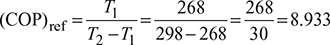
Work required,
- Heat pump:
(COP)HP =1 + (COP)ref =1 + 8.933= 9.933

18.8 ❐ POWER CONSUMPTION OF A REFRIGERATING MACHINE
The power consumption of a refrigerating machine is determined in terms of kW. However the power consumption of the driving motor is sometimes rated in horsepower (H.P). we have
where Wref is in kW and HP is in metric units,
where Q1 = refrigerating capacity in kW
Since 1 TR = 3.5167 kW, therefore
Example 18.4
The ambient air temperature during summer and winter in a particular locality are 45°C and 15°C respectively. Find the value of Carnot COP for an air-conditioner for cooling and heating, corresponding to refrigeration temperatures of 5°C for summer and heating temperature of 55°C for winter. Also find the theoretical power consumption per ton of refrigeration in each case.
Solution
For summer: T1 = 273 + 5 = 278 K, T2 = 45 + 273 = 318 K
For cooling, Carnot ![]()
Power consumption, ![]()
For winter: T1 = 273 + 15 = 288 K, T2 = 273 + 55 = 328 K
For heating, ![]()
Power consumption, ![]()
Example 18.5
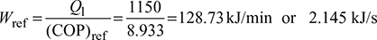
A refrigerator has working temperature of −30°C and 35°C. The actual COP is 0.75 of the maximum. Calculate the power consumption, and heat rejected to the surroundings per ton of refrigeration.
Solution
Power consumption per ton ![]()
18.9 ❐ AIR REFRIGERATION CYCLES
There are two types of air refrigeration cycles.
- Open air refrigeration cycle.
- Closed (or dense) air refrigeration cycle.
18.9.1 Open Air Refrigeration Cycle
In an open air refrigeration cycle, the air is directly (at atmospheric pressure) led to the space to be cooled (i.e. refrigerator). The air is then allowed to circulate through the cooler and returned to the compressor to start another cycle. This requires size of the compressor and expander to be large. The moisture is regularly carried away by the air circulated through the refrigerator. This leads to the formation of frost at the end of expansion process and clog the line. Therefore, a drier is required in the open cycle system.
18.9.2 Closed (or dense) Air Refrigeration Cycle
In a closed air refrigeration cycle, the air is passed through the pipes and components parts of the system at all times. The air is used for absorbing heat from the other fluid (say brine) which is circulated into the space to be cooled. The air does not come in contact directly with the space to be cooled.
This system has the following advantages over the open cycle:
- The suction pressure is higher than that of atmospheric pressure Therefore, the volume of air handled by the compressor and expander is smaller.
- The operating pressure ratio can be reduced, which results in higher coefficient of performance.
18.10 ❐ REVERSED CARNOT CYCLE
A reversed Carnot cycle, using air as working medium is shown in Fig. 18.5 on p-v and T-s diagrams. The reversed Carnot cycle is represented by four processes as described below:
- Process 1-2: Isentropic compression
During this process, the pressure of air increases from p1 to p2, specific volume decreases from v1 to v2 and temperature increases from T1 to T2. No heat is absorbed or rejected by air during this process.
- Process 2-3: Isothermal compression
During this process, the pressure of air increases from p2 to p3 and specific volume decreases from v2 to v3. Temperature remains constant at T2 = T3.
Heat rejected by air per kg of air, q2-3 = area 2-3-3′-2′
= T3 (s2 – s3) = T2 (s2 – s3)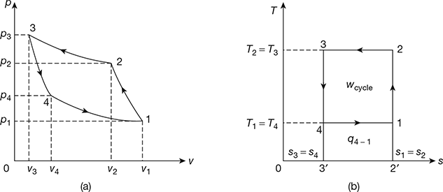
Figure 18.5 Reversed Carnot Cycle: (a) p-v diagram, (b) T-s diagram
- Process 3-4: Isentropic expansion
During this process, the pressure of air decreases from p3 to p4, specific volume increases from v3 to v4 and temperature decreases from T3 to T4. No heat is absorbed or rejected by air.
- Process 4-1: Isothermal expansion
During this process, the pressure of air decreases from p4 to p1 and specific volume increases from v4 to v3. Temperature remains constant at T4 = T1.
Heat absorbed by air (or heat extracted from cold body) per kg of air.
Work done during the cycle per kg of air, wcycle = q2−3 − q4−1 = are 1-2-3-4
Coefficient of performance of refrigeration system,
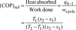
18.10.1 Temperature Limitations for Reversed Carnot Cycle
For a reversed Carnot cycle.
where T1 = lower temperature, and
T2 = higher temperature.
The COP of the reversed Carnot cycle may be improved by the following methods:
- Decreasing the higher temperature T2 of hot body.
- Increasing the lower temperature T1 of cold body.
The temperature T1 and T2 cannot be varied at will, due to certain functional limitations. The lowest possible refrigeration temperature is T1 = 0 (absolute zero) at which (COP)ref = 0. The highest possible refrigeration temperature is T1 = T2 i.e. when the refrigeration temperature is equal to the temperature of the surroundings at which,(COP)ref = ∞. Thus reversed Carnot COP varies between 0 and ∞.
To obtain maximum possible COP in any application,
- the cold body temperature T1 should be as high as possible, and
- the hot body temperature T2 should be as low as possible.
The lower the refrigeration temperature required and higher the temperature of heat rejection to the surroundings, the larger is the power consumption of the refrigerating machine. Also, the lower is the refrigeration temperature required, the lower is the refrigerating capacity obtained.
The temperature T2 in winter is less than T2 in summer. Therefore, (COP)ref in winter will be higher than (COP)ref in summer. In other words, the Carnot refrigerator works more efficiently in winter than in summer. Similarly, if the lower temperature fixed by the refrigeration application is high, the (COP)ref will be high. Thus a Carnot refrigerator used for making ice at 0°C (273 K) will have less (COP)ref than a Carnot refrigerator used for air-conditioning plant in summer at 20°C when the ambient air temperature is 40°C.
18.10.2 Vapour as a Refrigerant in Reversed Carnot Cycle
The reversed Carnot cycle can be made almost practical by operating in the liquid-vapour region of a pure substance as shown in Fig. 18.6 on T-s diagram.
- Process 1-2: Isentropic compression
The vapours during compression are wet and becomes dry saturated at the end of the process. Such a process is called wet compression. The temperature rises from T1 to T2.
Compression work per kg of refrigerant, w1−2 = h2 − h1 - Process 2-3: Condensation
During this process the temperature remains constant at T2. Heat is rejected from h2 to h3 and refrigerant gets converted to liquid at the end of process.
q2−3 = h2 − h3 = (hfg)t2 - Process 3-4: Isentropic expansion
During this process the flashing of the liquid refrigerant takes place with consequent temperature drop from T2 to T1. The refrigerant becomes wet at the end of expansion.
Work of expander, w3−4 = h3 − h4
- Process 4-1: Evaporation
During this process the wet refrigerant evaporates, heat is absorbed from the medium, and refrigeration effect is produced.
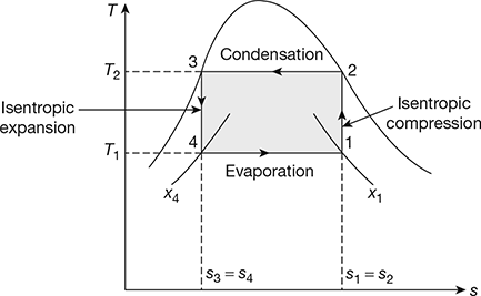
Figure 18.6 Reversed Carnot cycle with vapour as a refrigerant
Network, wnet = w1−2 −w3−4 = (h2 − h1) −(h3 − h4)

Example 18.6
A Carnot refrigerator has working temperatures of −30°C and 35°C. It operates with R-12 refrigerant as a working substance. Calculate the work of isentropic compression, isentropic expansion, refrigeration effect, and COP of the cycle per kg of refrigerant.
If the actual COP is 80 percent of the maximum, calculate the power consumption and heat rejected to the surroundings per ton of refrigeration.
Solution
Given: t1= −30°C, t2 = 35°C, Refrigerant = R-12, (COP)actual = 0.8(COP)max From the table of properties of R-12, we have (Refer to Fig. 18.6)
Now s1 = sf1 + x1 (sg1 − sf1) = 0.0371+ x1(0.7171− 0.371)
x1 = 0.951
x4 = 0.3218
Work of compression, w1−2 = h2 − h1 = 201.5−166.1= 35.4 kJ/kg
Work of expression, w3−4 = h3 − h4 = 69.5−62.1= 7.4 kg
Refrigerating effect, q4−1 = h1 − h4 =166.1−62.1=104 kJ/kg
Heat rejected, q2−3 = h2 − h3 = 201.5−69.5=132 kJ/kg
Network, wnet = w1−2 − w3−4 = 35.4 − 7.4 = 28 kJ/kg

Power consumption per ton of refrigeration ![]()
Heat rejected per ton of refrigeration to the surroundings = 3.5167 + 1.1761 = 4.6928 kW
18.10.3 Gas as a Refrigerant in Reversed Carnot Cycle
Figure 18.7 shows the p-v and T-s diagrams for the reversed Carnot cycle with a gas as a refrigerant.
- Process 1-2: Isentropic compression
During this process, the pressure increases from p1 to p2 and volume decreases from v1 to v2. Heat transfer is zero so that q1−2 = 0. Temperature of gas increases from T1 to T2.
Work done per kg of gas,
- Process 2-3: Isothermal Compression
During this process, the pressure increases from p2 to p3 and volume decreases from v2 to v3. The temperature remains constant at T2.
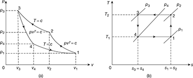
Figure 18.7 Reversed Carnot cycle with gas as a refrigerant: (a) p-v diagram, (b) T-s diagrame
Heat rejected, q2−3 = w2−3 for a perfect gas
- Process 3-4: Isentropic expansion
Pressure decreases from p3 to p4, volume increases from v3 to v4 and temperature decreases from T2 = T3 to T4 = T1

- Process 4-1: Isothermal expansion
Pressure decreases from p4 to p1, volume increases from v4 to v1, and temperature remains constant at T1.
Work done,

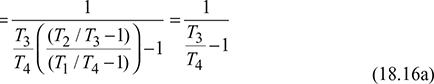
Refrigerating effect, q4−1 = w4−1 for a perfect gas
Net work of the cycle, wnet = w2−3 −w4−1
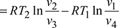
Refrigerating effect,

For the isentropic processes 1-2 and 3-4, we have
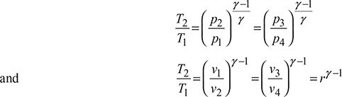
where r = compression ratio for the isentropic processes.
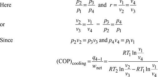
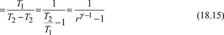
Thus, COP is a function of compression ratio only.
18.10.4 Limitations of Reversed Carnot Cycle
The limitations of reversed Carnot cycle are:
- The isentropic compression and expansion processes require high speed while the isothermal condensation and evaporation processes require an extremely low speed. This variation in speed of air of a cycle is not practicable.
- It is difficult to design an expander to handle a mixture of largely liquid and partly vapour.
- Because of the internal irreversibilities in the compressor and the expander, the actual COP of the reversed Carnot cycle is very low.
- With gas as refrigerant, it is not possible to devise, in practice, isothermal processes of heat absorption and rejection.
- The stroke volume of gas cycle cylinder is very large resulting in poor actual COP.
18.11 ❐ BELL-COLEMAN CYCLE (OR REVERSED BRAYTON OR JOULE CYCLE)
The Bell-Coleman air refrigeration cycle was developed by Bell-Coleman and Light Foot by reversing the Joule’s or Brayton’s air cycle. The schematic diagram of such a cycle is shown in Fig. 18.8. It consists of a compressor, a cooler, an expander, and a refrigerator. The p-v and T-s diagrams are shown in Fig. 18.9.
- Process 1-2: Isentropic compression
The cold air from the refrigerator is drawn into the compressor cylinder where it is compressed isentropically. The pressure and temperature of air increases and the specific volume decreases from v1 to v2. No heat is absorbed or rejected by the air.
- Process 2-3: Constant pressure cooling
The warm air from the compressor is passed into the cooler where it is cooled at constant pressure p3 = p2. The temperature decreases from T2 to T3 and specific volume reduces from v2 to v3.
Heat rejected by air, q2–3= cp(T2 − T3) - Process 3-4: Isentropic expansion
The air from the cooler is drawn into the expander cylinder where it is expanded isentropically from p3 to p4. The temperature falls from T3 to T4 and specific volume increases from v3 to v4. No heat is absorbed or rejected by air during this process.
- Process 4-1: Constant pressure expansion
The cold air from the expander is passed to the refrigerator where it is expanded at constant pressure p4 = p1.The temperature of air increases from T4 to T1 and specific volume increases from v4 to v1.
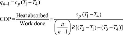
Heat absorbed by air (or extracted from the refrigerator), q4−1 = cp (T1 −T4)

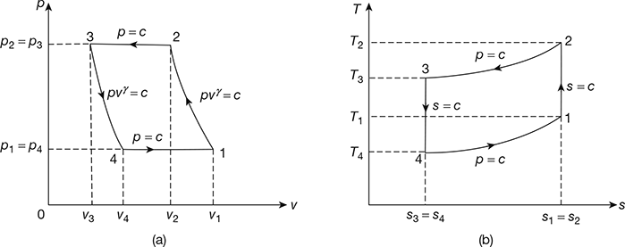
Figure 18.9 Bell-Coleman cycle: (a) p-v diagram, (b) T-s diagrame
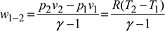
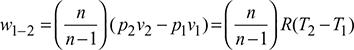
Work done during the cycle per kg of air,

For isentropic compression process 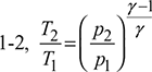 and for isentropic expansion process 3-4,
Since p2 = p3 and p1 = p4, therefore, ![]()

where ![]()

18.11.1 Bell-Coleman Cycle with Polytropic Processes
Let the compression and expansion processes take place according to the polytropic law. pvn = const.
- Process 1-2: Polytropic compression
Work done per kg of air,
- 2. Process 3-4: Polytropic expansion

Net work done during the cycle per kg of air,

- Heat absorbed during constant pressure process 4-1.

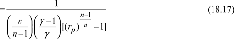
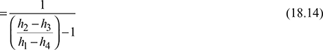
- For n = γ, Eq. (18.17) reduces to Eq. (18.16b)
- For n < γ, (COP)poly > (COP)isen
- For n > γ, (COP)poly < (COP)isen
Therefore, for obtaining higher COP, the compression and expansion index should be kept less than 1.4.
Example 18.7
A closed cycle refrigeration system working between 5 bar and 20 bar extracts 144 MJ of heat per hour. The air enters the compressor at 6°C and the expander at 22°C. The unit operates at 320 rpm. Calculate by assuming isentropic compression and expansion:
- Power required to operate the unit.
- Bore of compressor, and
- Refrigerating capacity in tonnes of ice at 0°C per day.
The following data is available:
| Stroke for double acting compressor and expander | = 300 mm |
| Mechanical efficiency of compressor | = 80% |
| Mechanical efficiency of expander | = 85% |
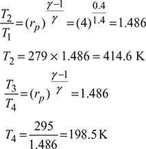
Given: p1 = p4 = 5 bar, p2 = p3 = 20 bar, Q4-1 = 144 MJ/h or 2400 kJ/min, T1 = 273 + 6 = 279 K, T3 = 273 + 22 = 295 K, N = 320 rpm, L = 300 mm, ηc = 0.80, ηe = 0.85, = 1.4
For p-v and T-s diagrams, refer to Fig. 18.9.
-
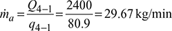
Heat extracted from the refrigeration system per kg of air,
q4−1 = cp (T1 −T4)=1.005 (279 −198.5) =80.9 kJ/kgMass of air circulated,
Work done during isentropic compression process 1-2,

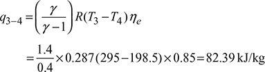
Work done during isentropic expansion process 3-4,
Net work done per kg of air supplied to the system,
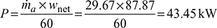
qnet = w1−2 −w3−4 =170.26 −82.39=87.87 kJ/kgPower required to operate the system,
- p1V1 =maRT1
Also
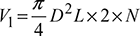 (for double acting compressor)
- Refrigerating capacity of the system per day = q4−1 ×ma ×60 × 24
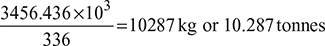
= 80.9 × 29.67 × 60 × 24 = 3456.436 MJ
Assuming latent heat of ice = 336 kJ/kg
Ice formation capacity of system =
Example 18.8
A closed cycle reversed Brayton refrigerator is required for a capacity of 12TR. The cooler pressure is 4.5 bar and the refrigerator pressure is 1.5 bar. The air is cooled in the cooler at a temperature of 45°C and the temperature of air at inlet to compressor is 20°C. Calculate for the ideal cycle: (a) COP, (b) mass of air circulated per minute, (c) theoretical displacement of compressor piston, (d) theoretical displacement of expander piston, and (e) net power per tonne of refrigeration. The compression and expansion are isentropic.
Solution
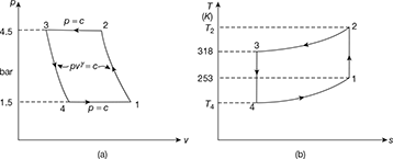
Given: Q = 12TR, p1 = p4 = 1.5 bar, p2 = p3 = 4.5 bar, T1 = 273 − 20 = 253 K, T3 = 273 + 45 = 318 K.
The p-v and T-s diagrams are shown in Fig. 18.10.
- Heat extracted per minute, Q = 211 × 12 = 2532 kJ/min
Heat extracted from the refrigerator per kg of air,
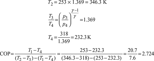
q = cp (T1 −T4)=1.005(253 − 232.3)= 20.8 kJ/kgMass of air circulated,

- Work done per minute = ṁa (Heat rejected – Heat extracted)
= ṁa cp [(T2 − T3) − (T1 −T4)]= 121.73 × 1.005 [(346.3 – 318) – (253 – 232.3)]= 929.77 kJ/min
Net power per tonne of refrigeration =

Example 18.9
Dense air is used as refrigerant in Reverse-Brayton or Bell-Coleman or Joule cycle. Draw T-s and p-v diagrams for the cycle. Derive the expression for COP in terms of pressure ratio. If temperatures at the end of heat absorption and heat rejection are 0°C and 30°C respectively, the pressure ratio is 4 and the pressure in the cooler is 4 bar determine the temperatures at all state points and volume flow rates at inlet to compressor and at exit of turbine for 1 TR cooling capacity.
Solution
The T-s and p-v diagrams are shown in Fig. 18.11(a) and the schematic diagram in Fig. 18.11(b).
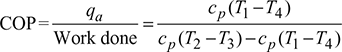


Figure 18.11 Bell-Coleman cycle: (a) p-v diagram, (b) T-s diagram, (c) Schematic diagram

Heat extracted per minute = 1 × 211 = 211 kJ/min
Heat extracted from cold chamber per kg of air
Mass flow rate of air,
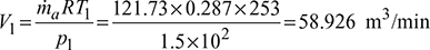
Volume handled by the compressor,
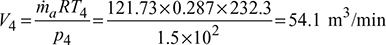
Volume handled by expander,
Example 18.10
An air refrigeration used for food storage provides 30 TR. The temperature of air entering the compressor is 10°C and temperature at exit of cooler is 30°C. Calculate:
- COP of the cycle, and
- Power required per tonne of refrigeration by the compressor.
The quantity of air circulated in the system is 3600 kg/h. The compression and expansion processes follow the law pv1.3 = const. and γ = 1.4, cp = 1.005 kJ/kg.K for air.
Given: Q = 30 TR, T1 = 273 + 10 = 283 K, T3 = 273 + 30 = 303 K, ṁa = 3600 kg/h, n = 1.3
- Heat extracted from the refrigerator, Q = 30 × 211 = 6330 kJ/min
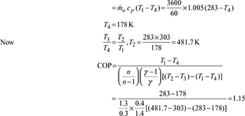
- Heat absorbed,

Work done per minute,

Power required per ton of refrigeration
Example 18.11
A dense air refrigeration cycle operates between pressures of 4 bar and 20 bar. The air temperature after heat rejection to surroundings is 40°C and air temperature at exit of refrigeration is 8°C. The isentropic efficiencies of compressor and expander are 0.82 and 0.86 respectively. Determine the compressor and expander work per TR. COP, and power required per TR. Take γ = 1.4 and cp = 1.005 kJ/kg.K.
Solution
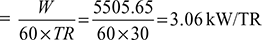
Given: p1 = p4 = 4 bar, p2 = p3 = 20 bar, T3 = 273 + 40 = 313 K, T1 = 273 + 8 = 281 K, ηc = 0.82, ηe = 0.86, γ = 1.4, cp = 1.005 kJ/kg.K.
The p-v and T-s diagrams are shown in Fig. 18.12
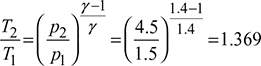
Process 1-2: Isentropic compression

Process 3-4: isentropic expansion

Isentropic efficiency of compressor, ![]()
Isentropic efficiency of expander, ![]()

Refrigerating effect per kg of air, q4′–1 = cp(T1 − T4′) = 1.005 (281 − 213.7) = 67.6 kJ/kg
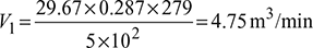
Mass flow rate of air, ![]()
Compressor work per TR, Wc = ṁacp (T2′ − T1) = 3.12× 7.005(481− 281)= 627.12 kJ/min
Expander work per TR, We = ṁacp (T3 − T4′) = 3.12×1.005(313− 213.7)= 311.36 kJ/min
Net work done, Wnet = Wc − We = 627.12 − 311.36 = 315.76 kJ/min
Power required per TR =![]()
18.12 ❐ REFRIGERANTS
A refrigerant may be defined as a substance which absorbs heat through expansion or vaporization and loses it through condensation in a refrigeration system.
18.13 ❐ CLASSIFICATION OF REFRIGERANTS
- Primary refrigerants: They take part directly in refrigeration and cool the substance on absorption of their latent heat. Some of the primary refrigerants are NH3, CO2CH3, C12, CH2C12, SO2, C2H5C1 and Freon group.
- Secondary refrigerants: They are first cooled with the help of primary refrigerant and then used for cooling other substances by absorption of their sensible heat only e.g. ice, solid CO2.
Primary refrigerants may be grouped as follows:
- Halo-Carbon compounds: They contain one or more of three halogens, fluorine, chlorine and bromine. Commercially they are sold under the names as Freon, Genetron, Irontron and Areton, They are used in domestic commercial and industrial refrigerating devices. Some of their important examples are:
Carbon tetrachloride − R10 : CC14 Trichloromono-fluro methane − R11 : CC13F Dichloro-difluro methane − R12 : CC12F2 Monobromotri-fluro methane − R13 : CBrF3 - Azeotropes: They are the mixtures of different refrigerants. They do not under go any separation with changes in temperature and pressure, e.g.
R-500 (73.8% R12 + 26.2% R-152) : CC12F2 + CH3CH F2
R-502 (48.8% R22 + 51.2% R-115) : CHC1F2 + CC1 F2 CF3
- Hydrocarbons: They are hydrocarbons, e.g.
Methane − R50 : CH4 Ethane − R170 : C2H6 Propane − R200 : C2H8 - Inorganic compounds:
Ammonia − R717 : NH3 Water − R718 : H20 Air − R720 : − Carbon dioxide − R744 : CO2 - Unsaturated organic compounds: They contain ethylene or propylene as main constituents, e.g.
Ethylene − R1150 : C2H4 Propylene − R1720 : C3H6 Trichloroethylene − R1120 : C2H4Cl3
- Halo-Carbon compounds: They contain one or more of three halogens, fluorine, chlorine and bromine. Commercially they are sold under the names as Freon, Genetron, Irontron and Areton, They are used in domestic commercial and industrial refrigerating devices. Some of their important examples are:
18.14 ❐ DESIGNATION OF REFRIGERANTS
- For a compound derived from a saturated hydrocarbon denoted by the chemical formula
CmHnFpC1q
In which (n + p + q) = 2m + 2, the complete designation of a refrigerant is
R(m − l)(n + 1)(p) - The brominated refrigerants are denoted by putting an additional B and a number to denote as to how many chlorine atoms are replaced by bromine atoms.
- In the case of isomers, i.e., compounds with the same chemical formula but different molecular structure, subscrips a, b, etc. are used after the designations.
- Unsaturated compounds, for which (n + p + q) = 2m, are distinguished by putting the digit 1 before (m − 1).
- For inorganic refrigerants, numerical designations have been given according to then molecular weight added to 700.
- In the case of butane, C4H10 and higher hydrocarbons, arbitrary designation R 600 is used.
18.15 ❐ DESIRABLE PROPERTIES OF REFRIGERANTS
A good refrigerant should have the following properties:
- Thermodynamic properties
- Low boiling point
- Low freezing point
- High saturation temperature
- High latent heat of vaporization
- High critical pressure and temperature.
- Chemical properties
- Non-toxic
- Non-flammable
- Non-explosive
- Non-corrosive
- Chemically stable
- Odourless
- Physical properties
- Low specific volume
- High thermal conductivity
- High electrical insulation
- Low specific heat
- Miscibility with lubricating oil.
- Other properties
- Ease of leakage detection
- Ease of handling
- High COP
- Ease of availability and of low cost.
- Low power consumption per ton of refrigeration.
18.16 ❐ APPLICATIONS OF REFRIGERANTS
The refrigerants and their applications are given in Table 18.1.
The primary-refrigerants are further classified into the following four groups
- Halo-carbon refrigerants
- A zoetrope refrigerants.
- Inorganic refrigerants, and
- Hydro-carbon refrigerants.
- Halo-carbon Refrigerants: The commonly used halo-carbon refrigerants, their applications and method of leak testing are given in Table 18.2.
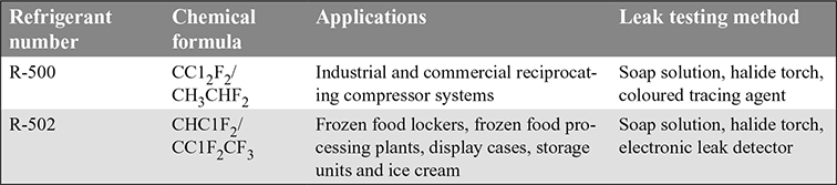
- Azeotrope Refrigerants: The term ‘azeotrope’ refers to a stable mixture of refrigerants whose vapour and liquid phases retain identical compositions over a wide range of temperatures.
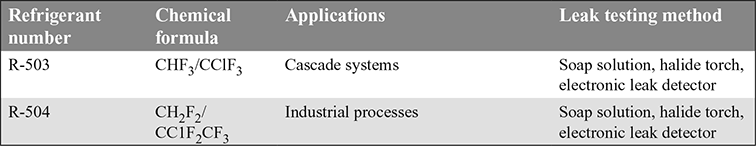
Some of the azeotropic refrigerants, their applications and method of leak testing are given in Table 18.3.
Table 18.1 Refrigerants and their applications
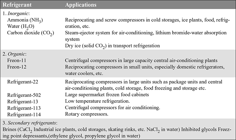
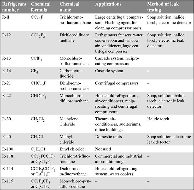
Table 18.3 Azeotrope refrigerantss
- 3. Inorganic Refrigerants: The various inorganic refrigerants, their applications and leak testing method are given in Table 18.4.
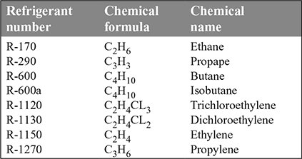
- 4. Hydro-Carbon Refrigerants: The various hydro-carbons are given in Table 18.5. They are mostly used for industrial and commercial installations.
Table 18.4 Inorganic refrigerants
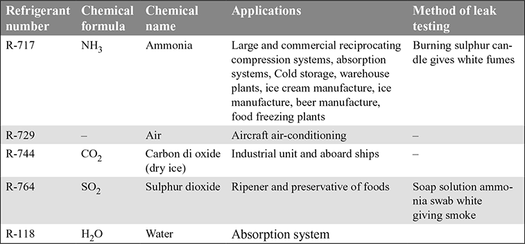
Table 18.5 Hydrocarbon refrigerants
- 5. Ozone Layer Depletion: Stratosphere is about 25-30 km away from the earth’s surface. It contains ozone (O3). Ozone is formed in the stratosphere by the reaction that occurs when sunlight interacts with oxygen. This ozone shelters the earth from ultraviolet (UV) radiation. This protection is essential for human health. This ozone is easily destroyed by the UV radiation. The sun’s radiation will break down the O3 molecule into a standard O2 molecule and elemental free oxygen (O) atom. More O3 is produced through photosynthesis and the bonding of O2 with free oxygen O. Thus ozone is constantly being formed and destroyed in the stratosphere.
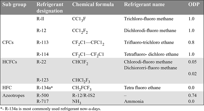
In the stratosphere, UV radiation will break off a chlorine atom (Cl) from the CFC and HCFC molecule. The chlorine atom destroys many O3 molecules The depleted O3 molecules in the stratosphere let more UV radiation reach the earth This causes an increase in skin cancers and frequency of cataracts in humans; weakens human immune system and decreases plant and marine life. Ozone depletion potential (ODP) has been used as an index to show the effect of a refrigerant on O3. Lower the ODP, it will be better. The ODP of some of the refrigerants is given in Table 18.6.
18.17 ❐ ECO-FRIENDLY REFRIGERANTS
With the increasing awareness of environmental degradation, the production, use and disposal of Chloro Fluoro Carbons (CFCs) and Hydro Chloro Fluoro Carbons (HCFCs) as refrigerants in mechanical refrigeration systems has become a subject of great concern. However, such systems are being developed using more eco-friendly refrigerants, such as
Eco-friendly refrigerants are also known as natural refrigerants. The important features and applications of eco-friendlv refrigerants are given in Table 18.7.
Table 18.7 Important features and applications of eco-friendly refrigerants

18.18 ❐ REFRIGERANT SELECTION
The choice of a refrigerant depends upon the following factors:
- Refrigeration temperature required.
- Refrigerating capacity of plant.
- Thermodynamic requirements: Normal boiling point, condensing and evaporating pressure, critical temperature and pressure, freezing point, volume of suction vapour per ton, COP, power consumption per ton etc
- Chemical requirements: Flammability, toxicity, action with water and oil (mixibility), and action with materials of construction
- Physical requirements: Dielectric strength, thermal conductivity, viscosity, heat capacity, surface tension, leak tendency and cost of refrigerant
- Economies.
- Equipment type and size.
- Application.
Multiple-choice Questions
- One tonne of refrigeration is equal to
- 211 kJ/min
- 220 kJ/min
- 420 kJ/min
- 620 kJ/min
- One tonne refrigerating machine means that
- one tonne is the total mass of the machine
- one tonne of refrigerant is used
- one tonne of water can be converted into ice
- one tonne of ice when melts from and at 0°C m 24 hours, the refrigeration effect produced is equivalent to 211 kJ/min.
- The ratio of heat extracted in the refrigerator to the work done on the refrigerant is called
- coefficient of performance of refrigeration
- coefficient of performance of heat pump
- relative coefficient of performance
- refrigerating efficiency
- The relative coefficient of performance is equal to
- Actual COP × Theoretical COP
- Air refrigerator works on
- Carnot cycle
- Rankine cycle
- reversed Carnot cycle
- Bell-Coleman cycle
- In air-conditioning of aeroplanes, using air as a refrigerant. the cycle used is
- reversed Carnot cycle
- reversed -Joule cycle
- reversed Brayton cycle
- reversed Otto cycle
- Co-efficient of performance of a Reversed Carnot cycle refrigerator working between higher temperature T2 and lower temperature T1
- will increase with increase in T1 keeping T2 fixed
- will decrease with increase in T1 keeping T2 fixed
- will first increase with increase in T1 and then decrease with increase in T1 keeping T2 fixed
- None of the above.
- A reversible refrigerator working between two fixed temperatures
- has the same COP whatever be the working substance
- has its COP increased for working substance with high enthalpy of evaporation
- has its COP increased for working substance with higher specific heats
- none of the above.
- Reversed Carnot cycle comprises
- two isentropic processes and two adiabatie processes
- two isentropic processes and two isothermal processes
- two isentropic processes and two constant pressure processes
- two isentropic processes and two constant volume processes.
- In Reversed Carnot cycle working on perfect gas
- Isothermal work of compression is equal to isothermal work of expansion
- Isentropic work of compression is equal to isentropic work of expansion
- Net work of the cycle is zero
- Net heat transfer of the cycle is zero.
- In a Reversed Carnot-cycle working on vapour
- Isentropic work of compression is equal to isentropic work of expansion
- Isothermal heat absorption is equal to isothermal heat rejection
- There is no work done during isothermal processes
- There is no work done during isentropic processes
- Reversed Carnot cycle assumes that all processes in the cycle are
- Non-flow only
- Steady flow only
- Non-flow or steady flow
- Transient flow
- Two Carnot refrigerators are employed, one for ice making and other for comfort cooling
- The COP of refrigerator for ice making is higher than that for the other
- The COP of refrigerator for ice making is lower than that for the other
- The COP of refrigerator for ice making is same as that for the other
- The COP of Carnot refrigerator will depend on refrigerant used
- A reverse Carnot cycle has a COP of 4. The ratio of higher temperature to lower temperature will be
- 1.5
- 2
- 1.25
- 2.5
- A Carnot refrigerator requires 70 kJ/min of work to produce one ton of refrigeration at -40°C. The COP of this refrigerator is
- 4
- 3
- 5
- not possible to find
- The coefficient of performance of refrigerator working on Reversed Carnot cycle with T1 being lower temperature and T2 being higher temperature is
- The coefficient of performance of Carnot refrigerator can be expressed (r = Volume compression ratio for isentropic compression)
- The COP of Carnot Refrigerator is 3 and it produces 1 ton of refrigeration. The work that will be done is equal to
- 210 kJ/min
- 70 kJ/min
- 100 kJ/min
- 200 kJ/min.
- The ratio of high temperature to low temperature for Reversed Carnot refrigerator is 1.25. The COP will be
- 2
- 3
- 4
- 5
- A carnot refrigerator operates between 300.3K and 273K. The fraction of cooling effect required as work input is
- (a) 20%
- (b) 10%
- (c) 50%
- (d) not possible to find with the data
- The relationship between COPheat pump COPrefrigerator for the same range of temperature operation is
- Carnot refrigerator absorbs heat at −13°C and requires 1 kW for each 6.5 kW of heat absorbed, the COP and temperature of heat rejections respectively are (0°C = 273K)
- COP = 6.5, t = 27°C
- COP = 7.5. t = 27°C
- COP = 6.5, t = 30°C
- COP = 7.5. t = 37°C
Review Questions
- How is the eff ectiveness of a refrigeration system measured?
- Explain the term “tonne of refrigeration”.
- Discuss the advantages of the dense air refrigerating system over an open air refrigeration system.
- What is the diff erence between a refrigerator and heat pump? Derive an expression for coeffi cient of performance for both if they are running on reversed Carnot cycle.
- Discuss the main differences between Reversed Carnot cycle operating on perfect gas and wet vapour.
- What is refrigeration?
- List few applications of refrigeration.
- Defi ne coeffi cient of performance.
- What are the SI units of refrigeration?
- Enumerate the various methods of refrigeration.
- Name few refrigeration systems.
- What is refrigeration effect?
Exercises
18.1 A Reversed Carnot Cycle operates on the following substances given below and the range of temperatures is 300K and 250K.
- Working substance is water between the range of dry saturated liquid to dry saturated vapour at 300K.
- Working substance is water in the form of super heated steam with the range of pressure from 0.01 bar to 0.05 bar.
- Working substance is CO2 in the super heated region with pressure range of 0.5 bar to 5 bar
- Working substance is air with pressure range of 1 bar to 10 bar
For the same heat rejected from the system of 60000 kJ/hr, determine the work input. Carnot coefficient of performance as refrigerator and as heat pump and the mass flow rate.
18.2 Carnot heat engine draws heat from a reservoir at temperature of 600 K and rejects heat to another reservoir at temperature T. This engine drives a Carnot reverse cycle refrigerator which absorbs heat from reservoir at temperature 200 K and reject heat to reservoir at temperature T. Determine the temperature T such that heat supplied to Carnot heat engine equal to heat absorbed by Carnot refrigerator.
18.3 A refrigerator using Carnot cycle requires 1.25 kW per tonne of refrigeration to maintain a temperature of −30°C. Find: (a) COP of the Carnot refrigerator, (b) temperature at which heat is rejected; and (c) Heat rejected per tonne of refrigeration.
[Ans. 2.8; 55.4°C; 284. kJ/min]
18.4 A Carnot cycle machine operates between the temperature limits of 47°C and 30°C. Determine the COP when it operates as (a) a refrigerator (b) a heat pump
[Ans. 3.16; 4.16]
18.5 Ten tonnes of fish is frozen to − 30°C per day. The fish enters the freezing chamber at 30°C and freezing occurs at −3°C. The frozen fish is cooled to − 30°C. The specific heats of fresh and frozen fish are 3.77 kJ/kg K and 1.67 kJ/kg K respectively while latent heat of freezing is 251.2 kJ/kg K. Find the tonnage of the plant which runs for 18 hours per day. The evaporator and condensor temperatures are −40°C and 45°C respectively. It the COP of the plant is 1.8, determine the power consumption of the plant in kW.
[Ans. 18.6 TR; 36.1 kW]
18.6 A Carnot refrigeration system has working temperature of −30°C and 40°C. what is the maximum COP possible? If the actual COP is 75% of the maximum calculate the actual refrigerating effect produced per kilowatt hour.
[Ans. 3.47; 0 713 TR]
18.7 A 5 tonne refrigerating machine operating on Bell Coleman cycle has an upper limit of pressure of 12 bar. The pressure and temperature at the start of compressor are 1 bar and 17°C respectively. The compressed air cooled at constant pressure to a temperature of 40°C enters the expansion cylinder. Assuming both the expansion and compression processes to be isentropic with γ = 1.4; Determine (a) COP; (b) the quantity of air in circulation per minute; (c) piston displacement of compressor and expander (d) bore of compressor and expansion cylinders. The unit runs at 250 r.p.m. and is double acting. Stroke length is 200 mm; and (e) power required to drive the unit. Take cp = 1 kJ/kg K; cv = 0.71 kJ/kg K; R = 0.287 kJ/kg K.
[Ans. 0.952; 7.65 kg/min; 6.37 m3/min; 3.35 m3 /min; 284 mm; 18.4 kW]
18.8 An air refrigerator used for food storage provides 50 TR. The temperature of air entering the compressor is 7°C and the temperature before entering into the expander is 27°C. Assuming a 70% mechanical efficiency find (a) actual COP and (b) The power required to run the compressor.
The quantity of air circulated in the system is 100 kg/min. The compression and expansion follow the law pv1.3 = constant. Take γ = 1.4 : cp = 1 kJ/kg K for air.
[Ans. 1.13; 110.6 kW]
18.9 A dense air refrigerating system operating between pressures of 17.5 bar and 3.5 bar is to produce 10 tonnes of refrigeration. Air leaves the refrigerating coils at −7°C and it leaves the air cooler at 15.5°C. Neglecting losses and clearance, calculate the net work done per minute and the coefficient of performance. For air cp = 1.005 kJ/kg K and γ = 1.4
[Ans. 1.237 kJ/min; 1.7]
18.10 A refrigerating plant is required to produce 2.5 tonnes of ice per day at −4°C from water at 20°C. If the temperature range in the compressor is between 25°C and −6°C, calculate power required to drive the compressor. Latent heat of ice = 335 kJ/kg and specific heat of ice = 2.1 kJ/kg K.
[Ans. 1 437 kW]
18.11 A refrigerator storage is supplied with 30 tonnes of fish at a temperature of 27°C. The fish has to be cooled to −9°C for preserving it for long period without determination. The cooling takes place in 10 hours. The specific heat of fish is 2.93 kJ/kg K above freezing point of fish and 1.26 kJ/kg K below freezing point of fish which is −3°C. The latent heat of freezing is 232 kJ/kg. What is the capacity of the plant in tonnes of refrigeration for cooling the fish? What would be the ideal COP between this temperature range? If the actual COP is 40% of the ideal, find the power required to run the cooling plant.
[Ans. 78 TR; 7.33; 93.3 kW]
18.12 An air refrigeration plant working on the Carnot cycle between the temperature limits of 34°C and −1°C has a capacity of 10 ton. Determine the power input to the plant.
18.13 An air refrigeration plant working on Carnot cycle produces refrigeration capacity equivalent to production of 10 tons of ice in 24 hours at 0°C from water at 20°C. The compressor temperature limits are 30°C and −15°C. Determine the power input to the plant. The latent heat of ice is 335 kJ/kg.
18.14 Find the minimum power input to perfect reversed heat engine that will produce 1 ton of ice per hour at −5°C from water at 15°C. The temperature limits of the reversed heat engine are 15°C and −5°C. Assume specific heat of ice as 2.1 kJ/kg. K and latent heat of ice as 335 kJ/kg.
ANSWERS TO MULTIPLE-CHOICE QUESTIONS
- a
- d
- a
- b
- d
- c
- a
- a
- b
- b
- c
- c
- b
- c
- b
- b
- c
- c
- c
- b
- b
- a