Chapter 13
Troubleshooting Multicast
This chapter covers the following topics:
IGMP Protocol Operation
IGMP Configuration and Verification
PIM Protocol Operation
PIM Configuration and Verification
Multicast and Virtual Port-channels (vPC)
Ethanalyzer Examples For Multicast
Multicast traffic is found in nearly every network deployed today. The concept of multicast communication is easy to understand. A host transmits a message that is intended for multiple recipients. Those recipients are enabled to listen specifically for the multicast traffic of interest and ignore the rest, which supports the efficient use of system resources. However, bringing this simple concept to life in a modern network can be confusing and misunderstood. This chapter introduces multicast communication using Cisco NX-OS. After discussing the fundamental concepts, it presents examples to demonstrate how to verify that the control plane and data plane are functioning as intended. Multicast is a broad topic, and including an example for every feature is not possible. The chapter primarily focuses on the most common deployment options for IPv4; it does not cover multicast communication with IPv6.
Multicast Fundamentals
Network communication is often described as being one of the following types:
Unicast (one-to-one)
Broadcast (one-to-all)
Anycast (one-to-nearest-one)
Multicast (one-to-many)
The concept of unicast traffic is simply a single source host sending packets to a single destination host. Anycast is another type of unicast traffic, with multiple destination devices sharing the same network layer address. The traffic originates from a single host with a destination anycast address. Packets follow unicast routing to reach the nearest anycast host, where routing metrics determine the nearest device.
Broadcast and multicast both provide a method of one-to-many communication on a network. What makes multicast communication different from broadcast communication is that broadcast traffic must be received and processed by each host that receives it. This typically results in using system resources to process frames that end up being discarded. Multicast traffic, in contrast, is processed only by devices that are interested in receiving the traffic. Multicast traffic is also routable across Layer 3 (L3) subnet boundaries, whereas broadcast traffic is typically constrained to the local subnet. Figure 13-1 demonstrates the difference between broadcast and multicast communication behavior.
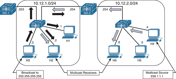
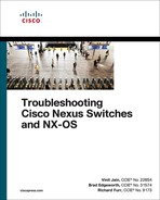
Figure 13-1 Multicast and Broadcast Communication
NX-2 is configured to route between the two L3 subnets in Figure 13-1. Host 3 sent a broadcast packet with a destination IP address 255.255.255.255 and destination MAC address of ff:ff:ff:ff:ff:ff. The broadcast traffic is represented by the black arrows. The broadcast packet is flooded from all ports in the L2 switch and received by each device in the 10.12.1.0/24 subnet. Host 1 is the only device running an application that needs to receive this broadcast. Receiving the packets on every other device results in wasted bandwidth and packet processing. NX-2 receives the broadcast but does not forward the packet to the 10.12.2.0/24 subnet. This behavior limits the scope of communication to only devices that are within the same broadcast domain or L3 subnet. Figure 13-1 demonstrates the potential ineffieciency of using broadcasts when certain hosts do not need to receive those packets.
Host 4 is sending multicast traffic represented by the white arrows to a group address of 239.1.1.1. These multicast packets are handled differently by the L2 switch and flooded only to Host 6 and NX-2, which is acting as an L3 multicast router (mrouter). NX-2 performs multicast routing and forwards the traffic to the L2 switch, which finally forwards the packets to Host 2. Because NX-1 is not receiving multicast traffic, the L2 switch does not consider it to be an mrouter. If NX-1 is reconfigured to be a multicast router with interested receivers attached, the packet is received and again multicast routed by NX-1 toward its receivers on other subnets. This theoretical behavior of NX-1 is mentioned to demonstrate that the scope of a multicast packet is limited by the time to live (TTL) value set in the IP header by the multicast source, not by an L3 subnet boundary as with broadcasts. Scope is also limited by administrative boundaries, access lists (ACL), or protocol-specific filtering techniques.
Multicast Terminology
The terminology used to describe the state and behaviors of multicast must be defined before diving further into concepts. Table 13-1 lists the multicast terms with their corresponding definition used throughout this chapter.
Table 13-1 Multicast Terminology
Term |
Definition |
mroute |
An entry in the Multicast Routing Information Base (MRIB). Different types of mroute entries are associated with the source tree or the shared tree. |
Incoming interface (IIF) |
The interface of a device that multicast traffic is expected to be received on. |
Outgoing interface (OIF) |
The interface of a device that multicast traffic is expected to be transmitted out of, toward receivers. |
Outgoing interface list (OIL) |
The OIFs on which traffic is sent out of the device, toward interested receivers for a particular mroute entry. |
Group address |
Destination IP address for a multicast group. |
Source address |
The unicast address of a multicast source. Also referred to as a sender address. |
L2 replication |
The act of duplicating a multicast packet at the branch points along a multicast distribution tree. Replication for multicast traffic at L2 is done without rewriting the source MAC address or decrementing the TTL, and the packets stay inside the same broadcast domain. |
L3 replication |
The act of duplicating a multicast packet at the branch points along a multicast distribution tree. Replication for multicast traffic at L3 requires PIM state and multicast routing. The source MAC address is updated and the TTL is decremented by the multicast router. |
Reverse Path Forwarding (RPF) check |
Compares the IIF for multicast group traffic to the routing table entry for the source IP address or the RP address. Ensures that multicast traffic flows only away from the source. |
Multicast distribution tree (MDT) |
Multicast traffic flows from the source to all receivers over the MDT. This tree can be shared by all sources (a shared tree), or a separate distribution tree can be built for each source (a source tree). The shared tree can be one-way or bidirectional. |
Protocol Independent Multicast (PIM) |
Multicast routing protocol that is used to create MDTs. |
RP Tree (RPT) |
The MDT between the last-hop router (LHR) and the PIM RP. Also referred to as the shared tree. |
Shortest-path tree (SPT) |
The MDT between the LHR and the first-hop router (FHR) to the source. Typically follows the shortest path as determined by unicast routing metrics. Also known as the source tree. |
Divergence point |
The point where the RPT and the SPT diverge toward different upstream devices. |
Upstream |
A device that is relatively closer to the source along the MDT. |
Downstream |
A device that is relatively closer to the receiver along the MDT. |
Sparse mode |
Protocol Independent Multicast Sparse mode (PIM SM) relies on explicit joins from a PIM neighbor before sending traffic toward the receiver. |
Dense mode |
PIM dense mode (PIM DM) relies on flood-and-prune forwarding behavior. All possible receivers are sent the traffic until a prune is received from uninterested downstream PIM neighbors. NX-OS does not support PIM DM. |
rendezvous point (RP) |
The multicast router that is the root of the PIM SM shared multicast distribution tree. |
Join |
A type of PIM message, but more generically, the act of a downstream device requesting traffic for a particular group or source. This can result in an interface being added to the OIL. |
Prune |
A type of PIM message, but more generically, the act of a downstream device indicating that traffic for the group or source is no longer requested by a receiver. This can result in the interface being removed from the OIL if no other downstream PIM neighbors are present. |
First-hop router (FHR) |
The L3 router that is directly adjacent to the multicast source. The FHR performs registration of the source with the PIM RP. |
Last-hop router (LHR) |
The L3 router that is directly adjacent to the multicast receiver. The LHR initiates a join to the PIM RP and initiates switchover from the RPT to the SPT. |
Intermediate router |
An L3 multicast-enabled router that forwards packets for the MDT. |
The example multicast topology in Figure 13-2 illustrates the terminology in Table 13-1.
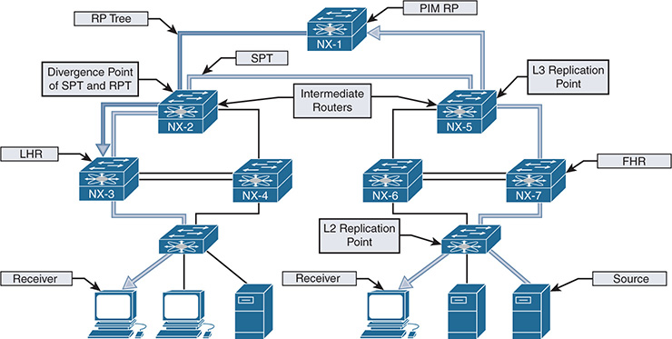
Figure 13-2 Visualizing Multicast Terminology
Figure 13-2 illustrates a typical deployment of PIM Sparse mode any-source multicast (ASM). The end-to-end traffic flow from the source to the receiver is made possible through several intermediate steps to build the MDT:
Step 1. Register the source with the PIM RP.
Step 2. Establish the RPT from the RP to the receiver.
Step 3. Establish the SPT from the source to the receiver.
When troubleshooting a multicast problem, determining which of these intermediate steps are completed guides the investigation based on the current state of the network. Each intermediate step consists of different checks, conditions, and protocol state machines that this chapter explores in depth.
Note
Figure 13-2 shows both the RP tree and the source tree in the diagram, for demonstration purposes. This state does not persist in reality because NX-3 prunes itself from the RP tree and receives the group traffic from the source tree.
Layer 2 Multicast Addresses
At L2, hosts communicate using Media Access Control Addresses (MAC addresses). A MAC address is 48-bits in length and is a unique identifier for a Network Interface Card (NIC) on the LAN Segment. MAC addresses are represented by a 12-digit hexadecimal number in the format 0012.3456.7890, or 00:12:34:56:78:90.
The MAC address used by a host is typically assigned by the manufacturer and is referred to as the Burned-In-Address (BIA). When two hosts in the same IP subnet communicate, the destination address of the L2 frame is set to the target device’s MAC address. As frames are received, if the target MAC address matches the BIA of the host, the frame is accepted and handed to higher layers for further processing.
Broadcast messages between hosts are sent to the reserved address of FF:FF:FF:FF:FF:FF. A host receiving a broadcast message must process the frame and pass its contents to a higher layer for additional processing where the frame is either discarded or acted upon by an application. As mentioned previously, for applications that do not need to be received by each host on the network the inefficiencies of broadcast communication can be improved upon by utilizing multicast.
Multicast communication requires a way of identifying frames at Layer 2 that are not broadcasts but can still be processed by one or more hosts on the LAN segment. This allows hosts that are interested in this traffic to process the frames and permits hosts that are not interested to throw away the frames and save processing and buffer resources.
The multicast MAC address differentiates multicast from unicast or broadcast frames at Layer 2. The reserved range of multicast MAC addresses designated in RFC 1112 are from 01:00:5E:00:00:00 to 01:00:5E:7F:FF:FF. The first 24 bits are always 01:00:5E. The first byte contains the individual/group (I/G) bit, which is set to 1 to indicate a multicast MAC address. The 25th bit is always 0, which leaves 23 bits of the address remaining. The Layer 3 group address is mapped to the remaining 23 bits to form the complete multicast MAC address (see Figure 13-3).
Figure 13-3 Mapping Layer 3 Group Address to Multicast MAC Address
When expanded in binary format, it is clear that multiple L3 group addresses must map to the same multicast MAC address. In fact, 32 L3 multicast group addresses map to each multicast MAC address. This is because 9 bits from the L3 group address do not get mapped to the multicast MAC address. The 4 high-order bits of the first octet are always 1110, and the remaining 4 bits of the first octet are variable. Remember that the multicast group IP address has the first octet in the range of 224 to 239. The first high-order bit of the third octet is ignored when the L3 group address is mapped to the multicast MAC address. This is the 25th bit of the multicast MAC address that is always set to zero. Combined, the potential variability of those 5 bits is 32 (25), which explains why 32 multicast groups map to each multicast MAC address.
For a host, this overlap means that if its NIC is programmed to listen to a particular multicast MAC address, it could receive frames for multiple multicast groups. For example, imagine that a source is active on a LAN segment and is generating multicast group traffic to 233.65.1.1, 239.65.1.1 and 239.193.1.1. All these groups are mapped to the same multicast MAC address. If the host is interested only in packets for 239.65.1.1, it cannot differentiate the different groups at L2. All the frames are passed to a higher layer where the uninteresting frames get discarded, while the interesting frames are sent to the application for processing. The 32:1 overlap must be considered when deciding on a multicast group addressing scheme. It is also advisable to avoid using groups X.0.0.Y and X.128.0.Y because the multicast MAC overlaps with 224.0.0.X. These frames are flooded by switches on all ports in the same VLAN.
Layer 3 Multicast Addresses
IPv4 multicast addresses are identified by the value of the first octet. A multicast address has the first octet of the address fall in the range of 224.0.0.0 to 239.255.255.255, which is also referred to as the Class D range. Viewed in binary format, a multicast address always has the first 4 bits in the first octet set to a value of 1110. The concept of subnetting does not exist with multicast because each address identifies an individual multicast group address. However, various address blocks within the 224.0.0.0/4 multicast range signify a specific purpose based on their address. The Internet Assigned Numbers Authority (IANA) lists the multicast address ranges provided in Table 13-2.
Table 13-2 IPv4 Multicast Address Space Registry
Designation |
Multicast Address Range |
Local Network Control Block |
224.0.0.0 to 224.0.0.255 |
Internetwork Control Block |
224.0.1.0 to 224.0.1.255 |
AD-HOC Block I |
224.0.2.0 to 224.0.255.255 |
Reserved |
224.1.0.0 to 224.1.255.255 |
SDP/SAP Block |
224.2.0.0 to 224.2.255.255 |
AD-HOC Block II |
224.3.0.0 to 224.4.255.255 |
Reserved |
224.5.0.0 to 224.251.255.255 |
DIS Transient Groups |
224.252.0.0 to 224.255.255.255 |
Reserved |
225.0.0.0 to 231.255.255.255 |
Source-Specific Multicast Block |
232.0.0.0 to 232.255.255.255 |
GLOP Block |
233.0.0.0 to 233.251.255.255 |
AD-HOC Block III |
233.252.0.0 to 233.255.255.255 |
Unicast Prefix-based IPv4 Multicast Addresses |
234.0.0.0 to 234.255.255.255 |
Reserved |
235.0.0.0 to 238.255.255.255 |
Organization-Local Scope |
239.0.0.0 to 239.255.255.255 |
The Local Network Control Block is used for protocol communication traffic. Examples are the All routers in this subnet address of 224.0.0.2 and the All OSPF routers address of 224.0.0.5. Addresses in this range should not be forwarded by any multicast router, regardless of the TTL value carried in the packet header. In practice, protocol packets that utilize the Local Network Control Block are almost always sent with a TTL of 1.
The Internetwork Control Block is used for protocol communication traffic that is forwarded by a multicast router between subnets or to the Internet. Examples include Cisco-RP-Announce 224.0.1.39, Cisco-RP-Discovery 224.0.1.40, and NTP 224.0.1.1.
Table 13-3 provides the well-known multicast addresses used by control plane protocols from the Local Network Control Block and from the Internetwork Control Block. It is important to become familiar with these specific reserved addresses so they are easily identifiable while troubleshooting a control plane problem.
Table 13-3 Well-Known Reserved Multicast Addresses
Description |
Multicast Address |
All Hosts in this subnet (all-hosts group) |
224.0.0.1 |
All Routers in this subnet (all-routers) |
224.0.0.2 |
All OSPF routers (AllSPFRouters) |
224.0.0.5 |
All OSPF DRs (AllDRouters) |
224.0.0.6 |
All RIPv2 routers |
224.0.0.9 |
All EIGRP routers |
224.0.0.10 |
All PIM routers |
224.0.0.13 |
VRRP |
224.0.0.18 |
IGMPv3 |
224.0.0.22 |
HSRPv2 and GLBP |
224.0.0.102 |
NTP |
224.0.1.1 |
Cisco-RP-Announce (Auto-RP) |
224.0.1.39 |
Cisco-RP-Discovery (Auto-RP) |
224.0.1.40 |
PTPv1 |
224.0.1.129 to 224.0.1.132 |
PTPv2 |
224.0.1.129 |
The Source-Specific Multicast Block is used by SSM, an extension of PIM Sparse mode that is described later in this chapter. It is optimized for one-to-many applications when the host application is aware of the specific source IP address of a multicast group. Knowing the source address eliminates the need for a PIM RP and does not require any multicast routers to maintain state on the shared tree.
The Organization-Local Scope is also known as the Administratively Scoped Block. These addresses are the multicast equivalent to RFC1918 unicast IP addresses, in which an organization assigns addresses from this range as needed. These addresses are not publicly routed or administered by IANA.
NX-OS Multicast Architecture
The multicast architecture of NX-OS inherits the same design principals as the operating system itself. Each component process is fully modular, creating the foundation for high availability (HA), reliability, and scalability.
The NX-OS HA architecture allows for stateful process restart and in-service software upgrades (ISSU) with minimal disruption to the data plane. As Figure 13-4 shows, the architecture is distributed with platform-independent (PI) components running on the supervisor module and hardware-specific components that forward traffic running on the I/O modules or system application-specific integrated circuits (ASIC).
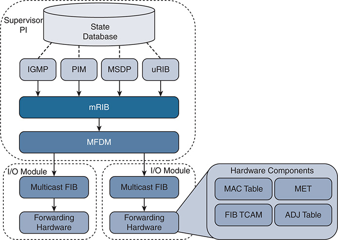
Figure 13-4 NX-OS Multicast Architecture
This common architecture is used across all NX-OS platforms. However, each platform can implement the forwarding components differently, depending on the capabilities of the specific hardware ASICs.
Each protocol, such as Internet Group Management Protocol (IGMP), Protocol Independent Multicast (PIM), and Multicast Source Discovery Protocol (MSDP), operates independently with its own process state, which is stored using the NX-OS Persistent Storage Services (PSS). Message and Transactional Services (MTS) is used to communicate and exchange protocol state messages with other services, such as the Multicast Routing Information Base (MRIB).
The MRIB is populated by client protocols such as PIM, IGMP, and MSDP to create multicast routing state entries. These mroute states describe the relationship of the router to a particular MDT and are populated by the various MRIB client protocols, such as IGMP, PIM, and IP. After MRIB creates the mroute state, it pushes this state to the Multicast Forwarding Distribution Manager (MFDM).
The MRIB interacts with the Unicast Routing Information Base (URIB) to obtain routing protocol metrics and next-hop information used during Reverse Path Forwarding (RPF) lookups. Any multicast packets that are routed by the supervisor in the software forwarding path are also handled by the MRIB.
MFDM is an intermediary between the MRIB and the platform-forwarding components. It is responsible for taking the mroute state from the MRIB and allocating platform resources for each entry. MFDM translates the MRIB into data structures that the platform components understand. The data structures are then pushed from MFDM to each I/O module, in the case of a distributed platform such as the Nexus 7000 series. In a nonmodular platform, MFDM distributes its information to the platform-forwarding components.
The Multicast Forwarding Information Base (MFIB) programs the (*, G) and (S, G) and RPF entries it receives from MFDM into hardware forwarding tables known as FIB (ternary content-addressable memory) TCAM. The TCAM is a high-speed memory space that is used to store a pointer to the adjacency. The adjacency is then used to obtain the Multicast Expansion Table (MET) index. The MET index contains information about the OIFs and how to replicate and forward the packet to each downstream interface. Many platforms and I/O modules have dedicated replication ASICs. The steps described here vary based on the type of hardware a platform uses, and troubleshooting at this depth typically involves working with Cisco TAC Support. Table 13-4 provides a mapping of multicast components to show commands used to verify the state of each component process.
Table 13-4 CLI Commands for Each Multicast Component
Component |
CLI Command |
IGMP |
show ip igmp route show ip igmp groups show ip igmp snooping groups |
PIM |
show ip pim route |
MSDP |
show ip msdp route show ip msdp sa-cache |
URIB |
show ip route |
MRIB |
show routing ip multicast [group] [source] show ip mroute |
MFDM |
show forwarding distribution ip multicast route show forwarding distribution ip igmp snooping |
Multicast FIB |
show forwarding ip multicast route module [module number] |
Forwarding Hardware |
show system internal forwarding ip multicast route show system internal ip igmp snooping |
TCAM, MET, ADJ Table |
Varies by platform and hardware type |
When Virtual Device Contexts (VDC) are used with the Nexus 7000 series, all of the previously mentioned PI components are unique to the VDC. Each VDC has its own PIM, IGMP, MRIB, and MFDM processes. However, in each I/O module, the system resources are shared among the different VDCs.
Replication
Multicast communication is efficient because a single packet from the source can be replicated many times as it traverses the MDT toward receivers located along different branches of the tree. Replication can occur at L2 when multiple receivers are in the same VLAN on different interfaces, or at L3 when multiple downstream PIM neighbors have joined the MDT from different OIFs.
Replication of multicast traffic is handled by specialized hardware, which is different on each Nexus platform. In the case of a distributed platform with different I/O modules, egress replication is used (see Figure 13-5).
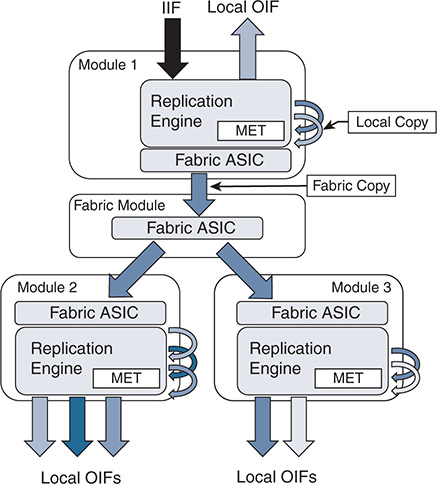
Figure 13-5 Egress Multicast Replication
The benefit of egress replication is that it allows all modules of the system to share the load of packet replication, which increases the forwarding capacity and scalability of the platform. As traffic arrives from the IIF, the following happens:
The packet is replicated for any receivers on the local module.
A copy of the packet is sent to the fabric module.
The fabric module replicates additional copies of the packet, one for each module that has an OIF.
At each egress module, additional packet copies are made for each local receiver based on the contents of the MET table.
The MET tables on each module contain a list of local OIFs. For improved scalability, each module maintains its own MET tables. In addition, multicast forwarding entries that share the same OIFs can share the same MET entries, which further improves scalability.
Protecting the Central Processing Unit
Multicast traffic can be directed to the Supervisor CPU for a number of reasons. A few possibilities include these:
Non-RPF traffic used to generate a PIM Assert message
A packet in which the TTL has expired in transit
The initial packet from a new source used to create a PIM register message
IGMP membership reports used to create entries in the snooping table
Multicast control plane packets for PIM or IGMP
NX-OS uses control plane policing (CoPP) policies to protect the supervisor CPU from excessive traffic. The individual CoPP classes used for multicast traffic vary from platform to platform, but they all serve an important role: to protect the device. Leaving CoPP enabled is always recommended, although exceptional cases require modifying some of the classes or policer rates. The currently applied CoPP policy is viewed with the show policy-map interface control-plane command. Table 13-5 provides additional detail about the default CoPP classes related to multicast traffic.
Table 13-5 CoPP Classes for Multicast
CoPP Class |
Description |
copp-system-p-class-multicast-router |
Matches multicast control plane protocols such as MSDP, PIM messages to ALL-PIM-ROUTERs (224.0.0.13) and PIM register messages (unicast) |
copp-system-p-class-multicast-host |
Matches IGMP packets |
copp-system-p-class-normal |
Matches traffic from directly connected multicast sources that is used to build PIM register messages |
Class-default |
Catchall class any packets that do not match another CoPP class |
In addition to CoPP, which polices traffic arriving at the supervisor, the Nexus 7000 series uses a set of hardware rate limiters (HWRL). The hardware rate limiters exist on each I/O module and control the amount of traffic that can be directed toward the supervisor. The status of the HWRL is viewed with the show hardware rate-limiter (see Example 13-1).
Example 13-1 Nexus 7000 Hardware Rate Limiters
! Output omitted for brevity
Units for Config: packets per second
Allowed, Dropped & Total: aggregated since last clear counters
rl-1: STP and Fabricpath-ISIS
rl-2: L3-ISIS and OTV-ISIS
rl-3: UDLD, LACP, CDP and LLDP
rl-4: Q-in-Q and ARP request
rl-5: IGMP, NTP, DHCP-Snoop, Port-Security, Mgmt and Copy traffic
Module: 3
Rate-limiter PG Multiplier: 1.00
R-L Class Config Allowed Dropped Total
+------------------+--------+---------------+---------------+-----------------+
L3 mtu 500 0 0 0
L3 ttl 500 12 0 12
L3 control 10000 0 0 0
L3 glean 100 1 0 1
L3 mcast dirconn 3000 13 0 13
L3 mcast loc-grp 3000 2 0 2
L3 mcast rpf-leak 500 0 0 0
L2 storm-ctrl Disable
access-list-log 100 0 0 0
copy 30000 7182002 0 7182002
receive 30000 27874374 0 27874374
L2 port-sec 500 0 0 0
L2 mcast-snoop 10000 34318 0 34318
L2 vpc-low 4000 0 0 0
L2 l2pt 500 0 0 0
L2 vpc-peer-gw 5000 0 0 0
L2 lisp-map-cache 5000 0 0 0
L2 dpss 100 0 0 0
L3 glean-fast 100 0 0 0
L2 otv 100 0 0 0
L2 netflow 48000 0 0 0
L3 auto-config 200 0 0 0
Vxlan-peer-learn 100 0 0 0
Table 13-6 describes each multicast HWRL.
Table 13-6 Hardware Rate Limiters for Multicast
R-L Class |
Description |
L3 mcast dirconn |
Packets for which the source is directly connected. These packets are sent to the CPU to generate PIM register messages. |
L3 mcast loc-grp |
Packets sent to the CPU at the LHR to trigger SPT switchover. |
L3 mcast rpf-leak |
Packets sent to the CPU to create a PIM assert message. |
L2 mcast-snoop |
IGMP membership reports, queries, and PIM hello packets punted to the CPU for IGMP snooping. |
As with the CoPP policy, disabling any of the HWRLs that are enabled by default is not advised. In most deployments, no modification to the default CoPP or HWRL configuration is necessary.
If excessive traffic to the CPU is suspected, incrementing matches or drops in a particular CoPP class or HWRL provide a hint about what traffic is arriving. For additional detail, an Ethanalyzer capture can look at the CPU-bound traffic for troubleshooting purposes.
NX-OS Multicast Implementation
Many network environments consist of a mix of Cisco NX-OS devices and other platforms. It is therefore important to understand the differences in default behavior between NX-OS and Cisco IOS devices. NX-OS has the following differences:
Multicast does not have to be enabled globally.
Certain features (PIM, MSDP) must be enabled before they are configurable. IGMP is automatically enabled when PIM is enabled.
Removing a feature removes all related configuration.
PIM dense mode is not supported.
Multipath support is enabled by default. This allows multicast traffic to be load-balanced across equal-cost multipath (ECMP) routes.
Punted multicast data packets are not replicated by default (this is enabled by configuring ip routing multicast software-replicate only if needed).
PIM IPsec AH-MD5 neighbor authentication is supported.
PIM snooping is not supported.
IGMP snooping uses an IP-based forwarding table by default. IGMP snooping based on MAC address table lookup is a configurable option.
NX-OS platforms might require the allocation of TCAM space for multicast routes.
Static Joins
In general, static joins should not be required when multicast has been correctly configured. However, this is a useful option for troubleshooting in certain situations. For example, if a receiver is not available, a static join is used to build multicast state in the network.
NX-OS offers the ip igmp join-group [group] [source] interface command, which configures the NX-OS device as a multicast receiver for the group. Providing the source address is not required unless the join is for IGMPv3. This command forces NX-OS to issue an IGMP membership report and join the group as a host. All packets received for the group address are processed in the control plane of the device. This command can prevent packets from being replicated to other OIFs and should be used with caution.
The second option is the ip igmp static-oif [group] [source] interface command, which statically adds an OIF to an existing mroute entry and forwards packets to the OIF in hardware. The source option is used only with IGMPv3. It is important to note that if this command is being added to a VLAN interface, you must also configure a static IGMP snooping table entry with the ip igmp snooping static-group [group] [source] interface [interface name] VLAN configuration command to actually forward packets.
Clearing an MROUTE Entry
A common way to clear the data structures associated with a multicast routing entry is to use the clear ip mroute command. In Cisco IOS platforms, this command is effective in clearing the entry. However, in NX-OS, the data structures associated with a particular mroute entry might have come from any MRIB client protocol. NX-OS provides the commands necessary to clear the individual MRIB client entries. In NX-OS 7.3, the clear ip mroute * command was enhanced to automatically clear the individual client protocols as well as the MRIB entry. In older releases of NX-OS, it is necessary to issue additional commands to completely clear an mroute entry from the MRIB and all associated client protocols:
clear ip mroute * clears entries from the MRIB.
clear ip pim route * clears PIM entries created by PIM join messages.
clear ip igmp route * clears IGMP entries created by IGMP membership reports.
clear ip mroute data-created * clears MRIB entries created by receiving multicast data packets.
Multicast Boundary and Filtering
The Cisco IOS equivalent of a multicast boundary does not exist in NX-OS. In Cisco IOS, the multicast boundary command is a filter applied to an interface to create an administratively scoped boundary where multicast traffic can be filtered on the interface. The following control plane and data plane filtering techniques are used to create an administrative boundary in NX-OS:
Filter PIM join messages: ip pim jp-policy [route-map] [in | out]
Filter IGMP membership reports: ip igmp report-policy [route-map]
Data traffic filter: ip access-group [ACL] [in | out]
In addition, the ip pim border command can be configured on an interface to prevent the forwarding of any Auto-RP, bootstrap, or candidate-RP messages.
Event-Histories and Show Techs
NX-OS provides event-histories, which are an always-on log of significant process events for enabled features. In many cases, the event-history log is sufficient for troubleshooting in detail without additional debugging. The various event-history logs for multicast protocols and processes are referenced throughout this chapter for troubleshooting purposes. Certain troubleshooting situations call for an increase in the default event-history size because of the large volume of protocol messages. Each event-history type can be increased in size, independent of the other types. For PIM, the event-history size is increased with the ip pim event-history [event type] size [small | medium | large] configuration command. IGMP is increased with the ip igmp event-history [event type] size [small | medium | large] configuration command.
Each feature or service related to forwarding multicast traffic in NX-OS has its own show tech-support [feature] output. These commands are typically used to collect the majority of data for a problem in a single output that can be analyzed offline or after the fact. The tech support file contains configurations, data structures, and event-history output for each specific feature. If a problem is encountered and the time to collect information is limited, the following list of NX-OS tech support commands can be captured and redirected to individual files in bootflash for later review:
show tech-support ip multicast
show tech-support forwarding l2 multicast vdc-all
show tech-support forwarding l3 multicast vdc-all
show tech-support pixm
show tech-support pixmc-all
show tech-support module all
Knowing what time the problem might have occurred is critical so that the various system messages and protocol events can be correlated in the event-history output. If the problem occurred in the past, some or all of the event-history buffers might have wrapped and the events related to the problem condition could be gone. In such situations, increasing the size of certain event-history buffers might be useful for when the problem occurs again.
After collecting all the data, the files can be combined into a single archive and compressed for Cisco support to investigate the problem.
Providing an exhaustive list of commands for every possible situation is impossible. However, the provided list will supply enough information to narrow the scope of the problem, if not point to a root cause. Also remember that multicast problems are rarely isolated to a single device, which means it could be necessary to collect the data set from a peer device or PIM neighbor as well.
IGMP
Hosts use the IGMP protocol to dynamically join and leave a multicast group through the LHR. With IGMP, a host can join or leave a group at any time. Without IGMP, a multicast router has no way of knowing when interested receivers reside on one of its interfaces or when those receivers are no longer interested in the traffic. It should be obvious that, without IGMP, the efficiencies in bandwidth and resource utilization in a multicast network would be severely diminished. Imagine if every multicast router sent traffic for each group on every interface! For that reason, hosts and routers must support IGMP if they are configured to support multicast communication. In the NX-OS implementation of IGMP, a single IGMP process serves all virtual routing and forwarding (VRF) instances. If Virtual Device Contexts (VDC) are being used, an IGMP process runs on each VDC.
IGMPv1 was defined in RFC 1112 and provided a state machine and the messaging required for hosts to join and leave multicast groups by sending membership reports to the local router. Finding a device using IGMPv1 in a modern network is uncommon, but an overview of its operation is provided for historical purposes so that the differences and evolution in IGMPv2 and IGMPv3 are easier to understand.
A multicast router configured for IGMPv1 periodically sends query messages to the All-Hosts address of 224.0.0.1. The host then waits for a random time interval, within the bounds of a report delay timer, to send a membership report using the group address as the destination address for the membership report. The multicast router receives the message indicating that traffic for a specific group should be sent. When the router receives the membership report, it knows that a host on the segment is a current member of the multicast group and starts forwarding the group traffic onto the segment. A functional reason for using the group address as the destination of the membership report is so that hosts are aware of the presence of other receivers for the group on the same network. This allows a host to suppress its own report message, to reduce the volume of IGMP traffic on a segment. A multicast router needs to receive only a single membership report to begin sending traffic onto the segment.
When a host wants to join a new multicast group, it can immediately send a membership report for the group; it does not have to wait for a query message from a multicast router. However, when a host wants to leave a group, IGMPv1 does not provide a way to indicate this to the local multicast router. The host simply stops responding to queries. If the router receives no further membership reports, it sends three queries before pruning off the interface from the OIL and determining that interested receivers are no longer present.
IGMPv2
Defined in RFC 2236, IGMPv2 provides additional functionality over IGMPv1. It required an additional message to be defined to implement the new functionality. Figure 13-6 shows the IGMP message format.

Figure 13-6 IGMP Message Format
The IGMPv2 message fields are defined in the following list:
Type:
0x11 Membership query (general query or group specific query)
0x12 Version 1 membership report (used for backward compatibility)
0x16 Version 2 membership report
0x17 Leave group
Max Response Time: Used only in membership query messages and is set to zero in all other message types. This is used to tune the response time of hosts and the leave latency observed when the last member decides to leave the group.
Checksum: Used to ensure the integrity of the IGMP message.
Group Address: Set to zero in a general query and set to the group address when sending a group specific query. In a membership report or leave group message, the group address is set to the group being reported or left.
Note
IP packets carrying IGMP messages have the TTL set to 1 and the router alert option set in the IP header, to force routers to examine the packet contents.
In IGMPv2, an election to determine the IGMP querier is specified whenever more than one multicast router is present on the network segment. Upon startup, a multicast router sends an IGMP general query message to the All-Hosts group 224.0.0.1. When a router receives a general query message from another multicast router, a check is performed and the router with the lowest IP address assumes the role of the querier. The querier is then responsible for sending query messages on the network segment.
The process of joining a multicast group is similar in IGMPv2 to IGMPv1. A host responds to general queries as well as group-specific queries with a membership report message. A host implementation chooses a random time to respond, between zero seconds and the max-response-interval sent in the query message. A host can also send an unsolicited membership report when a new group is joined to initiate the flow of multicast traffic on the segment.
The leave group message was defined to address the IGMPv1 problem in which a host could not explicitly inform the network after deciding to leave a group. This message type is used to inform a router when the multicast group is no longer needed on the segment and all members have left the group. If a host is the last member to send a membership report on the segment, it should send a leave group message when the host no longer wants to receive the group traffic. This leave group message is sent to the All-Routers multicast address 224.0.0.2. When the querier receives this message, it sends a group-specific query in response, which is also a new functionality enhancement over IGMPv1. The group-specific query message uses the multicast group’s destination IP address, to ensure that any host listening on the group receives the query. These messages are sent based on the last member query interval. If a membership report is not received, the router prunes the interface from the OIL.
IGMPv3
IGMPv3 was specified in RFC 3376. It allows a host to support the functionality required for Source Specific Multicast (SSM). SSM multicast allows a receiver to specifically join not only the multicast group address, but also the source address for a particular group. Applications running on a multicast receiver host can now request specific sources.
In IGMPv3, the interface state of the host includes a filter mode and source list. The filter mode can be include or exclude. When the filter mode is include, traffic is requested only from the sources in the source list. If the filter mode is exclude, traffic is requested for any source except the ones present in the source list. The source list is an unordered list of IP unicast source addresses, which can be combined with the filter mode to implement source-specific logic. This allows IGMPv3 to signal only the sources of interest to the receiver in the protocol messages.
Figure 13-7 provides the IGMPv3 membership query message format, which includes several new fields when compared to the IGMPv2 membership query message, although the message type remains the same (0x11).
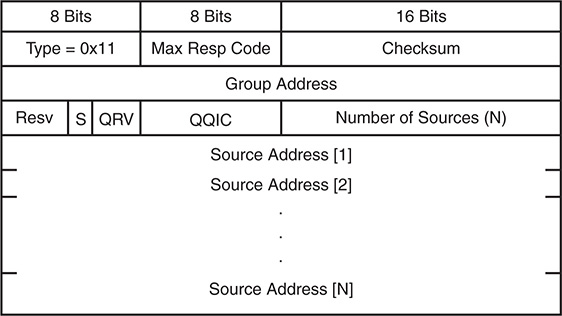
Figure 13-7 IGMPv3 Membership Query Message Format
The IGMPv3 membership query message fields are defined as follows:
Type 0x11: Membership query (general query, group specific query, or group and source specific query). These messages are differentiated by the contents of the group address and source address fields.
Max Resp Code: The maximum time allowed for a host to send a responding report. It enables the operator to tune the burstiness of IGMP traffic and the leave latency.
Checksum: Ensures the integrity of the IGMP message. It is calculated over the entire IGMP message.
Group Address: Set to zero for general query and is equal to the group address for group specific or source and group specific queries.
Resv: Set to zero and ignored on receipt.
S Flag: When set to 1, suppresses normal timer updates that routers perform when receiving a query.
QRV: Querier’s robustness variable. Used to overcome a potential packet loss. It allows a host to send multiple membership report messages to ensure that the querier receives them.
QQIC: Querier’s query interval code. Provides the querier’s query interval (QQI).
Number of Sources: Specifies how many sources are present in the query.
Source Address: Specific source unicast IP addresses.
Several differences appear when compared to IGMPv2. The most significant is the capability to have group and source specific queries, enabling query messages to be sent for specific sources of a multicast group.
The membership report message type for IGMPv3 is identified by the message type 0x22 and involves several changes when compared to the membership report message used in IGMPv2. Receiver hosts use this message type to report the current membership state of their interfaces, as well as any change in the membership state to the local multicast router. Hosts send this message to multicast routers using the group IP destination address of 224.0.0.22. Figure 13-8 shows the format of the membership report for IGMPv3.
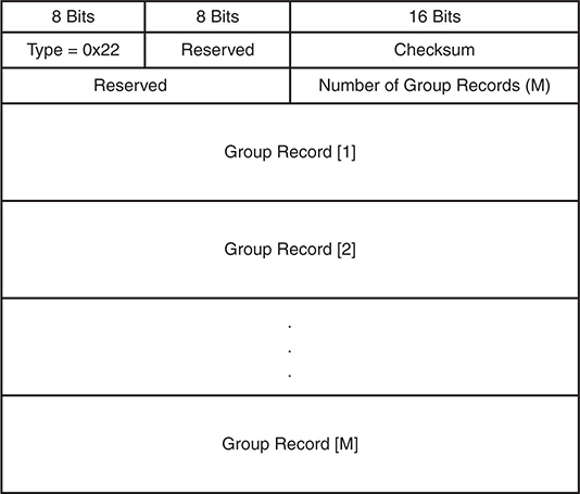
Figure 13-8 IGMPv3 Membership Report Message Format
Each group record in the membership report uses the format shown in Figure 13-9.
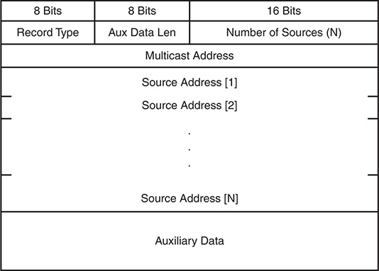
Figure 13-9 IGMPv3 Membership Report Group Record Format
The IGMPv3 membership report message fields are defined in the following list:
Type 0x22: IGMPv3 membership report
Reserved: Set to zero on transmit and ignored on receipt
Checksum: Verifies the integrity of the message
Number of Group Records: Provides the number of group records present in this membership report
Group Record: A block of fields that provides the sender’s membership in a single multicast group on the interface from which the report was sent
The fields in each group record are defined here:
Record Type: The type of group record.
Current-State Record: The current reception state of the interface
Mode_is_include: Filter mode is include
Mode_is_exclude: Filter mode is exclude
Filter-Mode-Change Record: Indication that the filter mode has changed
Change_to_Include_Mode: Filter mode change to include
Change_to_Exclude_Mode: Filer mode change to exclude
Source-List-Change Record: Indication that the source list has changed, not the filter mode
Allow_New_Sources: List new sources being requested
Block_Old_Sources: List sources no longer being requested
Aux Data Len: Length of auxiliary data in the group record.
Number of Sources: How many sources are present in this group record.
Multicast Address: The multicast group this record pertains to.
Source Address: The unicast IP address of a source for the group.
Auxiliary Data: Indication that auxiliary data is not defined for IGMPv3. The Aux Data Len should be set to zero and the auxiliary data should be ignored.
Additional Data: Accounted for in the IGMP checksum, but any data beyond the last group record is ignored.
The most significant difference in the IGMPv3 membership report when compared to the IGMPv2 membership report is the inclusion of the group record block data. This is where the IGMPv3-specific functionality for the filter mode and source list is implemented.
IGMPv3 is backward compatible with previous versions of IGMP and still follows the same general state machine mechanics. When a host or router running an older version of IGMP is detected, the queries and report messages are translated from IGMPv2 into their IGMPv3 equivalent. For example, an IGMPv3-compatible representation of an IGMPv2 membership report for 239.1.1.1 includes all sources in IGMPv3.
As in IGMPv2, general queries are still sent to the All-Hosts group 224.0.0.1 from the querier. Hosts respond with a membership report message, which now includes specific sources in a source list and includes or excludes logic in the record type field. Hosts that want to join a new multicast group or source use unsolicited membership reports. When leaving a group or specific source, a host sends an updated current state group record message to indicate the change in state. The leave group message found in IGMPv2 is not used in IGMPv3. If no other members are in the group or source, the querier sends a group or group and source-specific query message before pruning off the source tree. The multicast router keeps an interface state table for each group and source and updates it as needed when an include or exclude update is received in a group record.
IGMP Snooping
Without IGMP snooping, a switch must flood multicast packets to each port in a VLAN to ensure that every potential group member receives the traffic. Obviously, bandwidth and processing efficiency are reduced if ports on the switch do not have an interested receiver attached. IGMP snooping inspects (or “snoops on”) the higher-layer protocol communication traversing the switch. Looking into the contents of IGMP messages allows the switch to learn where multicast routers and interested receivers for a group are attached. IGMP snooping operates in the control plane by optimizing and suppressing IGMP messages from hosts, and operates in the data plane by installing multicast MAC address and port-mapping entries into the local multicast MAC address table of the switch. The entries created by IGMP snooping are installed in the same MAC address table as unicast entries. Despite the fact that different commands are used for viewing the entries installed by normal unicast learning and IGMP snooping, they share the same hardware resources provided by the MAC address table.
An IGMP snooping switch listens for IGMP query messages and PIM hello messages to determine which ports are connected to mrouters. When a port is determined to be an mrouter port, it receives all multicast traffic in the VLAN so that appropriate control plane state on the mrouter is created and sources are registered with the PIM RP, if applicable. The snooping switch also forwards IGMP membership reports to the mrouter to initiate the flow of multicast traffic to group members.
Host ports are discovered by listening for IGMP membership report messages. The membership reports are evaluated to determine which groups and sources are being requested, and the appropriate forwarding entries are added to the multicast MAC address table or IP-based forwarding table. An IGMP snooping switch should not forward membership reports to hosts because it results in hosts suppressing their own membership reports for IGMPv1 and IGMPv2.
If a multicast packet for the Network Control Block 224.0.0.0/24 arrives, it might need to be flooded on all ports. This is because devices can listen for groups in this range without sending a membership report for the group, and suppressing those packets could interrupt control plane protocols.
IGMP snooping is a separate process from the IGMP control plane process and is enabled by default in NX-OS. No user configuration is required to have the basic functionality running on the device. NX-OS builds its IGMP snooping table based on the group IP address instead of the multicast MAC address for the group. This behavior allows for optimal forwarding even if the L3 group addresses of multiple groups overlap to the same multicast group MAC address. The output in Example 13-2 demonstrates how to verify the IGMP snooping state and lookup mode for a VLAN.
Example 13-2 Verify IGMP Snooping
Global IGMP Snooping Information:
IGMP Snooping enabled
Optimised Multicast Flood (OMF) enabled
IGMPv1/v2 Report Suppression enabled
IGMPv3 Report Suppression disabled
Link Local Groups Suppression enabled
IGMP Snooping information for vlan 115
IGMP querier present, address: 10.115.1.254, version: 2, i/f Po1
Switch-querier disabled
IGMPv3 Explicit tracking enabled
IGMPv2 Fast leave disabled
IGMPv1/v2 Report suppression enabled
IGMPv3 Report suppression disabled
Link Local Groups suppression enabled
Router port detection using PIM Hellos, IGMP Queries
Number of router-ports: 1
Number of groups: 1
VLAN vPC function disabled
Active ports:
Po1 Po2 Eth3/19
It is possible to configure the device to use a MAC address–based forwarding mechanism on a per-VLAN basis, although it can lead to suboptimal forwarding because of address overlap. This option is configured in the VLAN configuration submode in Example 13-3.
Example 13-3 Enable MAC Address Lookup Mode
NX-2(config-vlan-config)# layer-2 multicast lookup mac
If multicast traffic arrives for a group that a host has not requested via a membership report message, those packets are forwarded to the mrouter ports only, by default. This is called optimized multicast flooding in NX-OS and is shown as enabled by default in Example 13-2. If this feature is disabled, traffic for an unknown group is flooded to all ports in the VLAN.
Note
Optimized multicast flooding should be disabled in IPv6 networks to avoid problems related to neighbor discovery (ND) that rely specifically on multicast communication. This feature is disabled with the no ip igmp snooping optimised-multicast-flood command in VLAN configuration mode.
IGMP membership reports are suppressed by default to reduce the number of messages the mrouter receives. Recall that the mrouter needs to receive a membership report from only one host for the interface to be added to the OIL for a group.
NX-OS has several options available when configuring IGMP snooping. Most of the configuration is applied per VLAN, but certain parameters can be configured only globally. Global values apply to all VLANs. Table 13-7 provides the default configuration parameters for IGMP snooping that apply globally on the switch.
Table 13-7 IGMP Snooping Global Configuration Parameters
Parameter |
CLI Command |
Description |
IGMP snooping |
ip igmp snooping |
Enables IGMP snooping on the active VDC. The default is enabled. Note: If the global setting is disabled, all VLANs are treated as disabled, whether they are enabled or not. |
Event-history |
ip igmp snooping event-history { vpc | igmp-snoop-internal | mfdm | mfdm-sum | vlan | vlan-events } size buffer-size |
Configures the size of the IGMP snooping history buffers. The default is small. |
Group timeout |
ip igmp snooping group-timeout { minutes | never } |
Configures the group membership timeout for all VLANs on the device. |
Link-local groups suppression |
ip igmp snooping link-local-groups-suppression |
Configures link-local groups suppression on the device. The default is enabled. |
Optimise-multicast-flood (OMF) |
ip igmp optimise-multicast-flood |
Configures OMF on all VLANs. The default is enabled. |
Proxy |
ip igmp snooping proxy general-inquiries [ mrt seconds ] |
Enables the snooping function to proxy reply to general queries from the multicast router while also sending round-robin general queries on each switchport with the specified MRT value. The default is 5 seconds. |
Report suppression |
ip igmp snooping report-suppression |
Limits the membership report traffic sent to multicast-capable routers on the device. When you disable report suppression, all IGMP reports are sent as is to multicast-capable routers. The default is enabled. |
IGMPv3 report suppression |
ip igmp snooping v3-report-suppression |
Configures IGMPv3 report suppression and proxy reporting on the device. The default is disabled. |
Table 13-8 provides the IGMP snooping configuration parameters, which are configured per VLAN. The per-VLAN configuration is applied in the vlan configuration [vlan-id] submode.
Table 13-8 IGMP Snooping per-VLAN Configuration Parameters
Parameter |
CLI Command |
Description |
IGMP snooping |
ip igmp snooping |
Enables IGMP snooping on a per-VLAN basis. The default is enabled. |
Explicit tracking |
ip igmp snooping explicit-tracking |
Tracks IGMPv3 membership reports from individual hosts for each port on a per-VLAN basis. The default is enabled. |
Fast leave |
ip igmp snooping fast-leave |
Enables the software to remove the group state when it receives an IGMP leave report without sending an IGMP query message. This parameter is used for IGMPv2 hosts when no more than one host is present on each VLAN port. The default is disabled. |
Group timeout |
ip igmp snooping group-timeout { minutes | never } |
Modifies or disables the default behavior of expiring IGMP snooping group membership after three missed general queries. |
Last member query interval |
ip igmp snooping last-member-query- interval seconds |
Sets the interval that the software waits after sending an IGMP query to verify that a network segment no longer has hosts that want to receive a particular multicast group. If no hosts respond before the last member query interval expires, the software removes the group from the associated VLAN port. Values range from 1 to 25 seconds. The default is 1 second. |
Optimize- multicast-flood |
ip igmp optimised-multicast-flood |
Configures OMF on the specified VLAN. The default is enabled. |
Proxy |
ip igmp snooping proxy general- queries [ mrt seconds ] |
Enables the snooping function to proxy reply to general queries from the multicast router while also sending round-robin general queries on each switchport with the specified MRT value. The default is 5 seconds. |
Snooping querier |
ip igmp snooping querier ip-address |
Configures a snooping querier on an interface when you do not enable PIM because multicast traffic does not need to be routed. |
Query timeout |
ip igmp snooping querier-timeout seconds |
Query timeout value for IGMPv2. The default is 255 seconds. |
Query interval |
ip igmp snooping query-interval seconds |
Time between query transmissions. The default is 125 seconds. |
Query max response time |
ip igmp snooping query-max-response- time seconds |
Max response time for query messages. The default is 10 seconds. |
Startup count |
ip igmp snooping startup-query-count value |
Number of queries sent at startup. The default is 2. |
Startup interval |
ip igmp snooping startup-query- interval seconds |
Interval between queries at startup. The default is 31 seconds. |
Robustness variable |
ip igmp snooping robustness-variable value |
Configures the robustness value for the specified VLANs. The default is 2. |
Report suppression |
ip igmp snooping report-suppression |
Limits the membership report traffic sent to multicast-capable routers on a per-VLAN basis. When you disable report suppression, all IGMP reports are sent as is to multicast-capable routers. The default is enabled. |
Static mrouter port |
ip igmp snooping mrouter interface interface |
Configures a static connection to a multicast router. The interface to the router must be in the selected VLAN. |
Layer 2 static group |
ip igmp snooping static-group group- ip-addr [ source source-ip-addr ] interface interface |
Configures a Layer 2 port of a VLAN as a static member of a multicast group. |
Link-local groups suppression |
ip igmp snooping link-local-groups- suppression |
Configures link-local groups suppression on a per-VLAN basis. The default is enabled. |
IGMPv3 report suppression |
ip igmp snooping v3-report-suppression |
Configures IGMPv3 report suppression and proxy reporting on a per-VLAN basis. The default is enabled per VLAN. |
Version |
ip igmp snooping version value |
Configures the IGMP version number for the specified VLANs. |
In a pure L2 deployment of multicast, a snooping querier must be configured. This applies to situations in which PIM is not enabled on any interfaces, no mrouter is present, and no multicast traffic is being routed between VLANs.
Note
When vPC is configured with IGMP snooping, configuring the same IGMP parameters on both vPC peers is recommended. IGMP state is synchronized between vPC peers with Cisco Fabric Services (CFS).
IGMP Verification
IGMP is enabled by default when PIM is enabled on an interface. Troubleshooting IGMP problems typically involves scenarios in which the LHR does not have an mroute entry populated by IGMP and the problem needs to be isolated to the LHR, the L2 infrastructure, or the host itself. Often IGMP snooping must be verified during this process because it is enabled by default and therefore plays an important role in delivering the queries to hosts and delivering the membership report messages to the mrouter.
In the topology in Figure 13-10, NX-1 is acting as the LHR for receivers in VLAN 115 and VLAN 116. NX-1 is also the IGMP querier for both VLANs. NX-2 is an IGMP snooping switch that is not performing any multicast routing. All L3 devices are configured for PIM ASM, with an anycast RP address shared between NX-3 and NX-4.
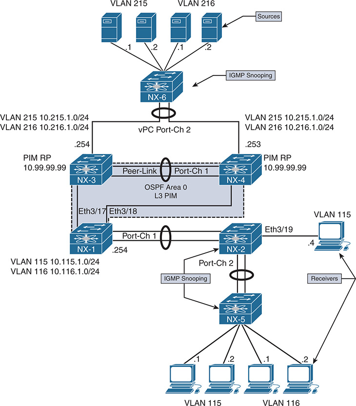
Figure 13-10 IGMP Verification Example Topology
If a receiver is not getting multicast traffic for a group, verify IGMP for correct state and operation. To begin the investigation, the following information is required:
Multicast Group Address: 239.215.215.1
IP address of the source: 10.215.1.1
IP address of the receiver: 10.115.1.4
LHR: NX-1
Scope of the problem: The groups, sources, and receivers that are not functioning
The purpose of IGMP is to inform the LHR that a receiver is interested in group traffic. At the most basic level, this is communicated through a membership report message from the receiver and should create a (*, G) state at the LHR. In most circumstances, checking the mroute at the LHR for the presence of the (*, G) is enough to verify that at least one membership report was received. The OIL for the mroute should contain the interface on which the membership report was received. If this check passes, typically the troubleshooting follows the MDT to the PIM RP or source to determine why traffic is not arriving at the receiver.
In the following examples, no actual IGMP problem condition is present because the (*, G) state exists on NX-1. Instead of troubleshooting a specific problem, this section reviews the IGMP protocol state and demonstrates the command output, process events, and methodology used to verify functionality.
Verification begins from NX-2, which is the IGMP snooping switch connected to the receiver 10.115.1.4, and works across the L2 network toward the mrouter NX-1. Example 13-4 contains the output of show ip igmp snooping vlan 115, which is where the receiver is connected to NX-2. This output is used to verify that IGMP snooping is enabled and that the mrouter port is detected.
Example 13-4 IGMP Snooping Status for VLAN 115
Global IGMP Snooping Information:
IGMP Snooping enabled
Optimised Multicast Flood (OMF) enabled
IGMPv1/v2 Report Suppression enabled
IGMPv3 Report Suppression disabled
Link Local Groups Suppression enabled
Optimised Multicast Flood (OMF) enabled
IGMPv3 Explicit tracking enabled
IGMPv2 Fast leave disabled
IGMPv1/v2 Report suppression enabled
IGMPv3 Report suppression disabled
Link Local Groups suppression enabled
Router port detection using PIM Hellos, IGMP Queries
Active ports:
Po1 Po2 Eth3/19
The Number of Groups field indicates that one group is present. The show ip igmp snooping groups vlan 115 command is used to obtain additional detail about the group, as in Example 13-5.
Example 13-5 VLAN 115 IGMP Snooping Group Membership
Type: S - Static, D - Dynamic, R - Router port, F - Fabricpath core port
Vlan Group Address Ver Type Port list
115 */* - R Po1
The last reporter is seen using the detail keyword, shown in Example 13-6.
Example 13-6 Detailed VLAN 115 IGMP Snooping Group Membership
IGMP Snooping group membership for vlan 115
Group addr: 239.215.215.1
Group ver: v2 [old-host-timer: not running]
IGMPv2 member ports:
IGMPv1/v2 memb ports:
Eth3/19 [0 GQ missed], cfs:false, native:true
vPC grp peer-link flag: include
M2RIB vPC grp peer-link flag: include
Note
If MAC-based multicast forwarding was configured for VLAN 115, the multicast MAC table entry can be confirmed with the show hardware mac address-table [module] [VLAN identifier] command. There is no software MAC table entry in the output of show mac address-table multicast [VLAN identifier], which is expected.
NX-2 is configured to use IP-based lookup for IGMP snooping. The show forwarding distribution ip igmp snooping vlan [VLAN identifier] command in Example 13-7 is used to find the platform index, which is used to direct the frames to the correct output interfaces. The platform index is also known as the Local Target Logic (LTL) index. This command provides the Multicast Forwarding Distribution Manager (MFDM) entry, which was discussed in the NX-OS “NX-OS Multicast Architecture” section of this chapter.
Example 13-7 IGMP Snooping MFDM Entry
Vlan: 115, Group: 239.215.215.1, Source: 0.0.0.0
Route Flags: 0
Outgoing Interface List Index: 13
Reference Count: 2
Platform Index: 0x7fe8
Vpc peer link exclude flag clear
Number of Outgoing Interfaces: 2
The Ethernet3/19 interface is populated by the membership report from the receiver. The Port-channel 1 interface is included as an outgoing interface because it is the mrouter port. Verify the platform index as shown in Example 13-8 to ensure that the correct interfaces are present and match the previous MFDM output. The show system internal pixm info ltl [index] command obtains the output from the Port Index Manager (PIXM). The IFIDX/RID is 0xd, which matches the Outgoing Interface List Index of 13.
Example 13-8 Verify the Platform LTL Index
MCAST LTLs allocated for VDC:1
============================================
LTL IFIDX/RID LTL_FLAG CB_FLAG
0x7fe8 0x0000000d 0x00 0x0002
mi | v5_f3_fpoe | v4_fpoe | v5_fpoe | clp_v4_l2 | clp_v5_l2 | clp20_v4_l3
| clp_cr_v4_l3 | flag | proxy_if_index
0x3 | 0x3 | 0x0 | 0x3 | 0x0 | 0x3 | 0x3 | 0x3 | 0x0 | none
Member info
------------------
IFIDX LTL
---------------------------------
Eth3/19 0x0012
Po1 0x0404
Note
If the IFIDX of interest is a port-channel, the physical interface is found by examining the LTL index of the port-channel. Chapter 5, “Port-Channels, Virtual Port-Channels, and FabricPath,” demonstrates the port-channel load balance hash and how to find the port-channel member link that will be used to transmit the packet.
At this point, the IGMP snooping control plane was verified in addition to the forwarding plane state for the group with the available show commands. NX-OS also provides several useful event-history records for IGMP, as well as other multicast protocols. The event-history output collects significant events from the process and stores them in a circular buffer. In most situations, for multicast protocols, the event-history records provide the same level of detail that is available with process debugs.
The show ip igmp snooping internal event-history vlan command provides a sequence of IGMP snooping events for VLAN 115 and the group of interest, 239.215.215.1. Example 13-9 shows the reception of a general query message from Port-channel 1, as well as the membership report message received from 10.115.1.4 on Eth3/19.
Example 13-9 IGMP Snooping VLAN Event-History
239.215.215.1|General
(*, 239.215.215.1) came on Eth3/19
02:19:33.729973 igmp [7177]: [7314]: SN: <115> Updated oif Eth3/19 for
(*, 239.215.215.1) entry
02:19:33.729962 igmp [7177]: [7314]: SN: <115> Received v2 report:
group 239.215.215.1 from 10.115.1.4 on Eth3/19
02:19:33.721639 igmp [7177]: [7314]: SN: <115> Report timer not running.
..starting with MRT expiry 10 for group: 239.215.215.1
02:19:33.721623 igmp [7177]: [7314]: SN: <115> Received v2 General query
from 10.115.1.254 on Po1
The Ethanalyzer tool provides a way to capture packets at the netstack component level in NX-OS. This is an extremely useful tool for troubleshooting any control plane protocol exchange. In Example 13-10, an Ethanalyzer capture filtered for IGMP packets clearly shows the receipt of the general query messages, as well as the membership report from 10.115.1.4. Ethanalyzer output is directed to local storage with the write option. The file can then be copied off the device for a detailed protocol examination, if needed.
Example 13-10 Ethanalyzer Capture of IGMP Messages on NX-2
1 02:29:24.420135 10.115.1.254 -> 224.0.0.1 IGMPv2 Membership Query, general
2 02:29:24.421061 10.115.1.254 -> 224.0.0.1 IGMPv2 Membership Query, general
3 02:29:24.430482 10.115.1.4 -> 239.215.215.1 IGMPv2 Membership Report group 239.215.215.1
NX-OS maintains statistics for IGMP snooping at both the global and interface level. These statistics are viewed with either the show ip igmp snooping statistics global command or the show ip igmp snooping statistics vlan [VLAN identifier] command. Example 13-11 shows the statistics for VLAN 115 on NX-2. The VLAN statistics also include global statistics, which are useful for confirming how many and what type of IGMP and PIM messages are being received on a VLAN. If additional packet-level details are needed, using Ethanalyzer with an appropriate filter is recommended.
Example 13-11 NX-2 VLAN 115 IGMP Snooping Statistics
Global IGMP snooping statistics: (only non-zero values displayed)
Packets received: 3783
Packets flooded: 1882
vPC PIM DR queries fail: 2
vPC PIM DR updates sent: 6
vPC CFS message response sent: 19
vPC CFS message response rcvd: 16
vPC CFS unreliable message sent: 403
vPC CFS unreliable message rcvd: 1632
vPC CFS reliable message sent: 16
vPC CFS reliable message rcvd: 19
STP TCN messages rcvd: 391
IM api failed: 1
VLAN 115 IGMP snooping statistics, last reset: never (only non-zero values displayed)
Packets received: 666
IGMPv2 reports received: 242
IGMPv2 queries received: 267
IGMPv2 leaves received: 4
PIM Hellos received: 1065
IGMPv2 reports suppressed: 1
IGMPv2 leaves suppressed: 2
Queries originated: 2
IGMPv2 proxy-leaves originated: 1
Packets sent to routers: 242
STP TCN received: 18
vPC Peer Link CFS packet statistics:
IGMP packets (sent/recv/fail): 300/150/0
IGMP Filtering Statistics:
Router Guard Filtering Statistics:
With NX-2 verified, the examination moves to the LHR, NX-1. NX-1 is the mrouter for VLAN 115 and the IGMP querier. The IGMP state on NX-1 is verified with the show ip igmp interface vlan 115 command, as in Example 13-12.
Example 13-12 NX-1 IGMP Interface VLAN 115 State
IGMP Interfaces for VRF "default"
Vlan115, Interface status: protocol-up/link-up/admin-up
IP address: 10.115.1.254, IP subnet: 10.115.1.0/24
Active querier: 10.115.1.254, version: 2, next query sent in: 00:00:06
Membership count: 1
Old Membership count 0
IGMP max response time: 10 secs, configured value: 10 secs
IGMP startup query interval: 31 secs, configured value: 31 secs
IGMP startup query count: 2
IGMP last member mrt: 1 secs
IGMP last member query count: 2
IGMP group timeout: 260 secs, configured value: 260 secs
IGMP querier timeout: 255 secs, configured value: 255 secs
IGMP unsolicited report interval: 10 secs
IGMP robustness variable: 2, configured value: 2
IGMP reporting for link-local groups: disabled
IGMP interface enable refcount: 1
IGMP interface immediate leave: disabled
IGMP VRF name default (id 1)
IGMP Report Policy: None
IGMP State Limit: None
IGMP interface statistics: (only non-zero values displayed)
General (sent/received):
v2-queries: 999/1082, v2-reports: 0/1266, v2-leaves: 0/15
Errors:
Interface PIM DR: Yes
Interface vPC SVI: No
Interface vPC CFS statistics:
DR queries sent: 1
DR queries rcvd: 1
DR updates sent: 1
DR updates rcvd: 3
The membership report NX-2 forwarded from the host is received on Port-channel 1. The query messages and membership reports are viewed in the show ip igmp internal event-history debugs output in Example 13-13. When the membership report message is received, NX-1 determines that state needs to be created.
Example 13-13 NX-1 IGMP Debugs Event-History
debugs events for IGMP process
04:39:34.349013 igmp [7011]: : Processing report for (*, 239.215.215.1)
(Vlan115), mrt: 10 sec
04:39:34.335543 igmp [7011]: : Sending SVI query packet to IGMP-snooping module
04:39:34.335541 igmp [7011]: : Send General v2 Query on Vlan115 (mrt:10 sec)
IGMP creates a route entry based on the received membership report in VLAN 115. The IGMP route entry is shown in the output of Example 13-14.
Example 13-14 IGMP Route Entry on NX-1
IGMP Connected Group Membership for VRF "default" - 1 total entries
Type: S - Static, D - Dynamic, L - Local, T - SSM Translated
Group Address Type Interface Uptime Expires Last Reporter
239.215.215.1 D Vlan115 01:59:49 00:03:49 10.115.1.4
IGMP must also inform the MRIB so that an appropriate mroute entry is created. This is seen in the show ip igmp internal event-history igmp-internal output in Example 13-15. An IGMP update is sent to the MRIB process buffer through Message and Transactional Services (MTS). Note that IGMP receives notification from MRIB that the message was processed and the message buffer gets reclaimed.
Example 13-15 IGMP Event-History of Internal Events
igmp-internal events for IGMP process
04:39:34.354419 igmp [7011]: [7564]: MRIB: Processing ack: reclaiming buffer
0x0x967cbe4, xid 0xffff000c, count 1
04:39:34.354416 igmp [7011]: [7564]: Received Message from MRIB minor 16
04:39:34.353742 igmp [7011]: [7566]: default: Sending IGMP update-route buffer
0x0x967cbe4, xid 0xffff000c, count 1 to MRIB
04:39:34.353738 igmp [7011]: [7566]: default: Moving MRIB txlist member marker
to version 12
04:39:34.353706 igmp [7011]: [7566]: Inserting IGMP update-update for
The message identifier 0xffff000c is used to track this message in the MRIB process events. Example 13-16 shows the MRIB processing of this message from the show routing ip multicast event-history rib output.
Example 13-16 MRIB Creating (*, G) State
04:39:34.355736 mrib [7170]::RPF change for (*, 239.215.215.1/32) (10.99.99.99)
04:39:34.354246 mrib [7170]::Doing multi-route add for "igmp"
04:39:34.354126 mrib [7170]:: OIF : Vlan115
04:39:34.354099 mrib [7170]::"igmp" add route (*, 239.215.215.1/32)
(list-00000000)[1],rpf Null 0.0.0.0(0.0.0.0), iod 0, mdt_encap_index 0, bidir: 0
, multi-route
04:39:34.353994 mrib [7170]::update IPC message (type:mts) from "igmp", 1 routes
When the MRIB process receives the MTS message from IGMP, an mroute is created for (*, 239.215.215.1/32) and the MFDM is informed. The RPF toward the PIM RP (10.99.99.99) is then confirmed and added to the entry.
The output of show ip mroute in Example 13-17 confirms that a (*, G) entry has been created by IGMP and the OIF was also populated by IGMP.
Example 13-17 IGMP Created MROUTE Entry on NX-1
IP Multicast Routing Table for VRF "default"
(*, 232.0.0.0/8), uptime: 10:08:39, pim ip
Incoming interface: Null, RPF nbr: 0.0.0.0
Outgoing interface list: (count: 0)
(*, 239.215.215.1/32), uptime: 01:59:08, igmp ip pim
Incoming interface: Ethernet3/18, RPF nbr: 10.1.13.3
(10.215.1.1/32, 239.215.215.1/32), uptime: 02:14:30, pim mrib ip
Incoming interface: Ethernet3/17, RPF nbr: 10.2.13.3
Outgoing interface list: (count: 1)
Vlan115, uptime: 01:59:08, mrib
Note
Additional events occur after this point when traffic arrives from the source, 10.215.1.1. The arrival of data traffic from the RP triggers a PIM join toward the source and creation of the (S, G) mroute. This is explained in the “PIM Any Source Multicast” section later in this chapter.
PIM Multicast
PIM is the multicast routing protocol used to build shared trees and shortest-path trees that facilitates the distribution of multicast traffic in an L3 network. As the name suggests, PIM was designed to be protocol independent. PIM essentially creates a multicast overlay network built upon the information available from the underlying unicast routing topology. The term protocol independent is based on the fact that PIM can use the unicast routing information in the Routing Information Base (RIB) from any source protocol, such as EIGRP, OSPF, or BGP. The unicast routing table provides PIM with the relative location of sources, rendezvous points, and receivers, which is essential to building a loop-free MDT.
PIM is designed to operate in one of two modes, dense mode or sparse mode. Dense mode (DM) operates under the assumption that receivers are densely dispersed through the network. In dense mode, the assumption is that all PIM neighbors should receive the traffic. In this mode of operation, multicast traffic is flooded to all downstream neighbors. If the group traffic is not required, the neighbor prunes itself from the tree. This is referred to as a push model because traffic is pushed from the root of the tree toward the leaves, with the assumption that there are many leaves and they are all interested in receiving the traffic. NX-OS does not support PIM dense mode because PIM sparse mode offers several advantages and is the most popular mode deployed in modern data centers.
PIM sparse mode (SM) is based on a pull model. The pull model assumes that receivers are sparsely dispersed through the network and that it is therefore more efficient to have traffic forward to only the PIM neighbors that are explicitly requesting the traffic. PIM sparse mode works well for the distribution of multicast when receivers are sparsely or densely populated in the topology. Because of its explicit join behavior, it has become the preferred mode of deploying multicast.
The role of PIM in the process of distributing multicast traffic from a source to a receiver is described by the following responsibilities:
Registering multicast sources with the PIM RP (ASM)
Joining an interested receiver to the MDT
Deciding which tree should be joined on behalf of the receiver
If multiple PIM routers exist on the same L3 network, determining which PIM router will forward traffic
This section of the chapter introduces the PIM protocol and messages PIM uses to build MDTs and create forwarding state. The different operating models of PIM SM are examined, including ASM, SSM, and Bi-Directional PIM (Bidir).
Note
RFC 2362 initially defined PIM as an experimental protocol that was later made obsolete by RFC 4601. Recently, RFC 4601 was updated by RFC 7761. The NX-OS implementation of PIM is based on RFC 4601.
PIM Protocol State and Trees
Before diving into the PIM protocol mechanics and message types, it is important to understand the different types of multicast trees. PIM uses both RPT and SPT to build loop-free forwarding paths for the purpose of delivering multicast traffic to the receiver. The RPT is rooted at the PIM RP, and the SPT is rooted at the source. Both tree types in PIM SM are unidirectional. Traffic flows from the root toward the leaves, where receivers are attached. If at any point the traffic diverges toward different branches to reach leaves, replication must occur.
The mroute state is often referred to when discussing multicast forwarding. With PIM multicast, the (*, G) state is created by the receiver at the LHR and represents the RPT’s relationship to the receiver. The (S, G) state is created by the receipt of multicast data traffic and represents the SPT’s relationship to the source.
As packets arrive on a multicast router, they are checked against the unicast route to the root of the tree. This is known as the Reverse Path Forwarding (RPF) check. The RPF check ensures that the MDT remains loop-free. When a router sends a PIM join-prune message to create state, it is sent toward the root of the tree from the RPF interface that is determined by the best unicast route to the root of the tree. Figure 13-11 illustrates the concepts of mroute state and PIM MDTs.
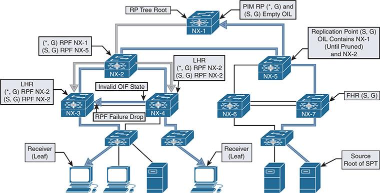
Figure 13-11 PIM MDTs and MROUTE State
PIM Message Types
PIM defines several message types that enable the protocol to discover neighbors and build MDTs. All PIM messages are carried in an IP packet and use IP protocol 103. Some messages, such as register and register-stop, use a unicast destination address and might traverse multiple L3 hops from source to destination. However, other messages, such as hello and join-prune, are delivered through multicast communication and rely on the ALL-PIM-ROUTERS well-known multicast address of 224.0.0.13 with a TTL value of 1. All PIM messages use the same common message format, regardless of whether they are delivered through multicast or unicast packets. Figure 13-12 shows the PIM control message header format.
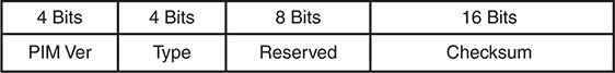
Figure 13-12 PIM Control Message Header Format
The PIM control message header format fields are defined in the following list:
PIM Version: The PIM version number is 2.
Type: This is the PIM message type (refer to Table 13-9).
Table 13-9 PIM Control Message Types
Type |
Message Type |
Destination Address |
Description |
0 |
Hello |
224.0.0.13 |
Used for neighbor discovery. |
1 |
Register |
RP Address (Unicast) |
Sent by FHR to RP to register a source. PIM SM only. |
2 |
Register-stop |
FHR (Unicast) |
Sent by RP to FHR in response to a register message. PIM SM only. |
3 |
Join-Prune |
224.0.0.13 |
Join or Prune from an MDT. Not used in PIM DM. |
4 |
Bootstrap |
224.0.0.13 |
Sent hop by hop from the bootstrap router to disperse RP mapping in the domain. Used in PIM SM and BiDIR. |
5 |
Assert |
224.0.0.13 |
Used to elect a single forwarder when multiple forwarders are detected on a LAN segment. |
6 |
Graft |
Unicast to the RPF neighbor |
Rejoins a previously pruned branch to the MDT |
7 |
Graft-Ack |
Unicast to the graft originator |
Acknowledges a graft message to a downstream neighbor. |
8 |
Candidate RP Advertisement |
BSR address (Unicast) |
Sent to the BSR to announce an RP’s candidacy. |
9 |
State refresh |
224.0.0.13 |
Sent hop by hop from the FHR to refresh prune state. Used only in PIM DM. |
10 |
DF Election |
224.0.0.13 |
Used in PIM BiDIR to elect a forwarder. Subtypes are offer, winner, backoff, and pass. |
11–14 |
Unassigned |
— |
— |
15 |
Reserved |
— |
RFC 6166, future expansion of the type field |
Reserved: This field is set to zero on transmit and is ignored upon receipt.
Checksum: The checksum is calculated on the entire PIM message, except for the multicast data packet portion of a register message.
The type field of the control message header identifies the type of PIM message being sent. Table 13-9 describes the various PIM message types listed in RFC 6166.
Note
This chapter does not cover the PIM messages specific to PIM DM because NX-OS does not support PIM DM. Interested readers should review RFC 3973 to learn about the various PIM DM messages.
PIM Hello Message
The PIM hello message is periodically sent on all PIM-enabled interfaces to discover neighbors and form PIM neighbor adjacencies. The PIM hello message is identified by a PIM message type of zero.
The value of the DR priority option is used in the Designated Router (DR) election process. The default value is one, and the neighbor with the numerically higher priority is elected as the PIM DR. If the DR priority is equal, then the higher IP address wins the election. The PIM DR is responsible for registering multicast sources with the PIM RP and for joining the MDT on behalf of the multicast receivers on the interface.
The hello message carries different option types in a Type, Length, Value (TLV) format. The various hello message option types follow:
Option Type 1: Holdtime is the amount of time to keep the neighbor reachable. A value of 0xffff indicates that the neighbor should never be timed out, and a value of zero indicates that the neighbor is about to go down or has changed its IP address.
Option Type 2: LAN prune delay is used to tune prune propagation delay on multiaccess LAN networks. It is used only if all routers on the LAN support this option, and it is used by upstream routers to figure out how long they should wait for a join override message before pruning an interface.
Option 3 to 16: Reserved for future use.
Option 18: Deprecated and should not be used.
Option 19: DR priority is used during the DR election.
Option 20: Generation ID (GENID) is a random 32-bit value on the interface where the hello message is sent. The value remains the same until PIM is restarted on the interface.
Option 24: Address list is used to inform neighbors about secondary IP addresses on an interface.
PIM Register Message
The PIM register message is sent in a unicast packet by the PIM DR to the PIM RP. The purpose of the register message is to inform the PIM RP that a source is actively sending multicast traffic to a group address. This is achieved by sending encapsulated multicast packets from the source in the register message to the RP. When data traffic is received from a source, the PIM DR performs the following:
The multicast data packet arrives from the source and is sent to the supervisor.
The supervisor creates hardware forwarding state for the group, builds the register message, and then sends the register message to the PIM RP.
Subsequent packets that the router receives from the source after the hardware forwarding state is built are not sent to the supervisor to create register messages. This is done to limit the amount of traffic sent to the supervisor control plane.
In contrast, a Cisco IOS PIM DR continues to send register messages until it receives a register-stop message from the PIM RP. NX-OS provides the ip pim register-until-stop global configuration command that modifies the default NX-OS behavior to behave like Cisco IOS. In most cases, the default behavior of NX-OS does not need to be modified.
The PIM register message contains the following fields:
Type: The value is 1 for a register message.
The Border Bit (B - Bit): This is set to zero on transmit and ignored on receipt (RFC 7761). RFC 4601 described PIM Multicast Border Router (PMBR) functionality that used this bit to designate a local source when set to 0, or set to 1 for a source in a directly connected cloud on a PMBR.
The Null-Register Bit: This is set to 1 if the packet is a null register message. The null register message encapsulates a dummy IP header from the source, not the full encapsulated packet that is present in a register message.
Multicast Data Packet: In a register message, this is the original packet sent by the source. The TTL of the original packet is decremented before encapsulation into the register message. If the packet is a null register, this portion of the register message contains a dummy IP header containing the source and group address.
PIM Register-Stop Message
The PIM register-stop message is a unicast packet that the PIM RP sends to a PIM DR in response to receiving a register message. The destination address of the register-stop is the source address used by the PIM DR that sent the register message. The purpose of the register-stop message is to inform the DR to cease sending the encapsulated multicast data packets to the PIM RP and to acknowledge the receipt of the register message. The register-stop message has the following encoded fields:
Type: The value is 2 for a register-stop message.
Group Address: This is the group address of the multicast packet encapsulated in the register message.
Source Address: This is the IP address of the source in the encapsulated multicast data packet from the register message.
PIM Join-Prune Message
The PIM join-prune message is sent by PIM routers to an upstream neighbor toward the source or the PIM RP using the ALL-PIM-ROUTERS multicast address of 224.0.0.13. A join is sent to build RP trees (RPT) to the PIM RP (shared trees) or to build shortest-path trees (SPT) to the source (source trees). The join-prune message contains an encoded list of groups and sources to be joined, as well as list of sources to be pruned. These are referred to as group sets and source lists.
Two types of group sets exist, and both types have a join source list and a prune source list. The wildcard group set represents the entire multicast group range (224.0.0.0/4), and the group-specific set represents a valid multicast group address. A single join-prune message can contain multiple group-specific sets but may contain only a single instance of the wildcard group set. A combination of a single wildcard group set and one or more group-specific sets is also valid in the same join-prune message. The join-prune message contains the following fields:
Type: Value is 3 for a join-prune message.
Unicast Neighbor Upstream Address: The address of the upstream neighbor that is the target of the message.
Holdtime: The amount of time to keep the join-prune state alive.
Number of Groups: The number of multicast group sets contained in the message.
Multicast Group Address: The multicast group address identifies the group set. This can be wildcard or group specific.
Number of Joined Sources: The number of joined sources for the group.
Joined Source Address 1 .. n: The source list that provides the sources being joined for the group. Three flags are encoded in this field:
S: Sparse bit. This is set to a value of 1 for PIM SM.
W: Wildcard bit. This is set to 1 to indicate that the encoded source address represents the wildcard in a (*, G) entry. When set to 0, it indicates that the encoded source address represents the source address of an (S, G) entry.
R: RP Bit. When set to 1, the join is sent to the PIM RP. When set to 0, the join is sent toward the source.
Number of Pruned Sources: The number of pruned sources for the group.
Pruned Source Address 1 .. n: The source list that provides the sources being pruned for the group. The same three flags are found here as in the joined source address field (S, W, R).
Note
In theory, it is possible that the number of group sets exceeds the maximum IP packet size of 65535. In this case, multiple join-prune messages are used. It is important to ensure that PIM neighbors have a matching L3 MTU size because a neighbor could sent a join-prune message that is too large for the receiving interface to accommodate. This results in missing multicast state on the receiving PIM neighbor and a broken MDT.
PIM Bootstrap Message
The PIM bootstrap message is originated by the Bootstrap Router (BSR) and provides an RP set that contains group-to-RP mapping information. The bootstrap message is sent to the ALL-PIM-ROUTERS address of 224.0.0.13 and is forwarded hop by hop throughout the multicast domain. Upon receiving a bootstrap message, a PIM router processes its contents and builds a new packet to forward the bootstrap message to all PIM neighbors per interface. It is possible for a bootstrap message to be fragmented into multiple Bootstrap Message Fragments (BSMF). Each fragment uses the same format as the bootstrap message. The PIM bootstrap message contains the following fields:
Type: The value is 4 for a bootstrap message.
No-Forward Bit: Instruction that the bootstrap message should not be forwarded.
Fragment Tag: Randomly generated number used to distinguish BSMFs that belong to the same bootstrap message. Each fragment carries the same value.
Hash Mask Length: The length, in bits, of the mask to use in the hash function.
BSR Priority: The priority value of the originating BSR. The value can be 0 to 255 (higher is preferred).
BSR Address: The address of the bootstrap router for the domain.
Group Address 1 .. n: The group ranges associated with the candidate-RPs.
RP Count 1 .. n: The number of candidate-RP addresses included in the entire bootstrap message for the corresponding group range.
Frag RP Count 1 .. m: The number of candidate-RP addresses included in this fragment of the bootstrap message for the corresponding group range.
RP Address 1 .. m: The address of the candidate-RP for the corresponding group range.
RP1 .. m Holdtime: The holdtime, in seconds, for the corresponding RP.
RP1 .. m Priority: The priority of the corresponding RP and group address. This field is copied from the candidate-RP advertisement message. The highest priority is zero and is per RP and per group address.
PIM Assert Message
A PIM assert message is used to resolve forwarder conflicts between multiple routers on a common network segment and is sent to the ALL-PIM-ROUTERS address of 224.0.0.13. The assert message is sent when a router receives a multicast data packet on an interface on which the router itself should have normally sent that packet out. This condition occurs when two or more routers are both sending traffic onto the same network segment. An assert message is also sent in response to receiving an assert message from another router. The assert message allows both sending routers to determine which router should continue forwarding and which router should cease forwarding, based on the metric value and administrative distance to the source or RP address. Assert messages are sent as group specific (*, G) or as source specific (S, G), which represents traffic from all sources to a group or for a specific source for a group. The assert message contains the following fields:
Type: The value is 5 for a PIM assert message.
Group Address: The group address for which the forwarder conflict needs to be resolved.
Source Address: The source address for which the forwarder conflict needs to be resolved. A value of zero indicates a (*, G) assert.
RPT-Bit: This value is set to 1 for (*, G) assert messages and 0 for (S, G) assert messages.
Metric Preference: The preference value assigned to the unicast routing protocol that provided the route to the source or PIM RP. This value refers to the administrative distance of the unicast routing protocol.
Metric: The unicast routing table metric for the route to the source or PIM RP.
PIM Candidate RP Advertisement Message
When the PIM domain is configured to use the BSR method of RP advertisement, each candidate PIM RP (C-RP) periodically unicasts a PIM candidate RP advertisement message to the BSR. The purpose of this message is to inform the BSR that the C-RP is willing to function as an RP for the included groups. The PIM candidate RP advertisement message has the following fields:
Type: The value is 8 for a candidate RP advertisement message.
Prefix Count: The number of group addresses included in the message. Must not be zero.
Priority: The priority of the included RP for the corresponding group addresses. The highest priority is zero.
Holdtime: The amount of time, in seconds, for which the advertisement is valid.
RP Address: The address of the interface to advertise as a candidate-RP.
Group Address 1 .. n: The group ranges associated with the candidate-RP.
PIM DF Election Message
In PIM BiDIR, the Designated Forwarder (DF) election chooses the best router on a network segment to forward traffic traveling down the tree from the Rendezvous Point Link (RPL) to the network segment. The DF is also responsible for sending packets traveling upstream from the local network segment toward the RPL. The DF is elected based on its unicast routing metrics to reach the Rendezvous Point Address (RPA). Routers on a common network segment use the PIM DF election message to determine which router is the DF, per RPA. The routers advertise their metrics in offer, winner, backoff, and pass messages, which are distinct submessage types of the DF election message. The PIM DF election message contains the following fields:
Type: The value is 10 for the PIM DF election message and has four subtypes.
Offer: Subtype 1. Sent by routers that believe they have a better metric to the RPA than the metric that has been seen in offers so far.
Winner: Subtype 2. Sent by a router when assuming the role of the DF or when reasserting in response to worse offers.
Backoff: Subtype 3. Used by the DF to acknowledge better offers. It instructs other routers with equal or worse offers to wait until the DF passes responsibility to the sender of the offer.
Pass: Subtype 4. Used by the old DF to pass forwarding responsibility to a router that has previously made an offer. The Old-DF-Metric is the current metric of the DF at the time the pass is sent.
RP Address: The RPA for which the election is taking place.
Sender Metric Preference: The preference value assigned to the unicast routing protocol that provided the route to the RPA. This value refers to the administrative distance of the unicast routing protocol.
Sender Metric: The unicast routing table metric that the message sender used to reach the RPA.
The Backoff message adds the following fields to the common election message format:
Offering Address: The address of the router that made the last (best) offer.
Offering Metric Preference: The preference value assigned to the unicast routing protocol that the offering router used for the route to the RPA.
Offering Metric: The unicast routing table metric that the offering router used to reach the RPA.
Interval: The backoff interval, in milliseconds, to be used by routers with worse metrics than the offering router.
The Pass message adds the following fields to the common election message format:
New Winner Address: The address of the router that made the last (best) offer.
New Winner Metric Preference: The preference value assigned to the unicast routing protocol that the offering router used for the route to the RPA.
New Winner Metric: The unicast routing table metric that the offering router used to reach the RPA.
PIM Interface and Neighbor Verification
NX-OS requires installation of the LAN_ENTERPRISE_SERVICES_PKG license to enable feature pim. The various PIM configuration commands are not available to the user until the license is installed and the feature is enabled.
PIM is enabled on an interface with the ip pim sparse-mode command, as in Example 13-18.
Example 13-18 Configuring PIM Sparse Mode on an Interface
version 7.2(2)D1(2)
interface Vlan115
interface Vlan116
interface Ethernet3/17
interface Ethernet3/18
After PIM is enabled on an interface, hello packets are sent and PIM neighbors form if there is another router on the link that is also PIM enabled.
Note
The hello interval for PIM is configured in milliseconds. The minimum accepted value is 1000 ms, which is equal to 1 second. If an interval lower than the default is needed to detect a failed PIM neighbor, use BFD for PIM instead of a reduced hello interval.
In the output of Example 13-19, NX-1 has formed PIM neighbors with NX-3 and NX-4. The output shows whether the neighbor is BiDIR capable and also provides the priority value of each neighbor which is used for DR election.
Example 13-19 PIM Neighbors on NX-1
PIM Neighbor Status for VRF "default"
Neighbor Interface Uptime Expires DR Bidir- BFD
Priority Capable State
10.2.13.3 Ethernet3/17 4d21h 00:01:34 1 yes n/a
10.1.13.3 Ethernet3/18 4d21h 00:01:19 1 yes n/a
PIM has several interface-specific parameters that determine how the protocol operates. The specific details are viewed for each PIM enabled interface with the show ip pim interface [interface identifier] command (see Example 13-20). The most interesting aspects of this output for troubleshooting purposes are the per-interface statistics, which provide useful counters for the different PIM message types and the fields related to the hello packets. The DR election state is also useful for determining which device registers sources on the segment for PIM sparse mode and which device forwards traffic to receivers known through IGMP membership reports.
Example 13-20 PIM Interface Parameters on NX-1
PIM Interface Status for VRF "default"
Ethernet3/18, Interface status: protocol-up/link-up/admin-up
IP address: 10.1.13.1, IP subnet: 10.1.13.0/24
PIM neighbor holdtime: 105 secs
PIM configured DR priority: 1
PIM configured DR delay: 3 secs
PIM border interface: no
PIM GenID sent in Hellos: 0x2cc432ed
PIM Hello MD5-AH Authentication: disabled
PIM Neighbor policy: none configured
PIM Join-Prune inbound policy: none configured
PIM Join-Prune outbound policy: none configured
PIM Join-Prune interval: 1 minutes
PIM Join-Prune next sending: 1 minutes
PIM BFD enabled: no
PIM passive interface: no
PIM VPC SVI: no
PIM Auto Enabled: no
In addition to the per-interface statistics, NX-OS provides statistics aggregated for the entire PIM router process (global statistics). This output is viewed with the show ip pim statistics command (see Example 13-21). These statistics are useful when troubleshooting PIM RP-related message activity.
Example 13-21 PIM Global Statistics
PIM Global Counter Statistics for VRF:default, last reset: never
Register processing (sent/received):
Registers: 1/3, Null registers: 1/293, Register-Stops: 4/2
Registers received and not RP: 1
Registers received for SSM/Bidir groups: 0/0
BSR processing (sent/received):
Bootstraps: 0/0, Candidate-RPs: 0/0
BSs from non-neighbors: 0, BSs from border interfaces: 0
BS length errors: 0, BSs which RPF failed: 0
BSs received but not listen configured: 0
Cand-RPs from border interfaces: 0
Cand-RPs received but not listen configured: 0
Auto-RP processing (sent/received):
Auto-RP Announces: 0/0, Auto-RP Discoveries: 0/0
Auto-RP RPF failed: 0, Auto-RP from border interfaces: 0
Auto-RP invalid type: 0, Auto-RP TTL expired: 0
Auto-RP received but not listen configured: 0
General errors:
Control-plane RPF failure due to no route found: 2
Data-plane RPF failure due to no route found: 0
Data-plane no multicast state found: 0
Data-plane create route state count: 5
If a specific PIM neighbor is not forming on an interface, investigate the problem using the event-history or Ethanalyzer facilities available in NX-OS. The show ip pim internal event-history hello output in Example 13-22 confirms that PIM hello messages are being sent from NX-1 and that hello messages are being received on Ethernet 3/18 from NX-3.
Example 13-22 PIM Event-History for Hello Messages
02:19:48.277882 pim [31641]: : Bidir Option present
02:19:48.277881 pim [31641]: : DR Priority Option: 1
02:19:48.277878 pim [31641]: : Holdtime Option: 105 secs
02:19:48.277875 pim [31641]: : Received Hello from 10.1.13.3 on Ethernet3/18,
length: 30
02:19:42.688032 pim [31641]: : iod = 64 - Send Hello on Ethernet3/18 from
10.1.13.1, holdtime: 105 secs, genID: 0x2cc432ed, dr-priority: 1, vpc: 0
02:19:41.714660 pim [31641]: : iod = 259 - Send Hello on Vlan116 from
10.116.1.254, holdtime: 105 secs, genID: 0xfb8dc7c, dr-priority: 1, vpc: 0
02:19:38.268071 pim [31641]: : iod = 258 - Send Hello on Vlan115 from
10.115.1.254, holdtime: 105 secs, genID: 0x2fd1ac5d, dr-priority: 1, vpc: 0
If additional detail about the PIM message contents is desired, the packets can be captured using the Ethanalyzer tool (see Example 13-23). The packet detail is examined locally using the detail option, or the capture may be saved for offline analysis with the write option.
Example 13-23 PIM Ethanalyzer Capture of a PIM Hello Message
Capturing on inband
Frame 1: 64 bytes on wire (512 bits), 64 bytes captured (512 bits)
Encapsulation type: Ethernet (1)
Arrival Time: Oct 29, 2017 00:48:35.186687000 UTC
[Time shift for this packet: 0.000000000 seconds]
Epoch Time: 1509238115.186687000 seconds
[Time delta from previous captured frame: 0.029364000 seconds]
[Time delta from previous displayed frame: 0.029364000 seconds]
[Time since reference or first frame: 3.751505000 seconds]
Frame Number: 5
Frame Length: 64 bytes (512 bits)
Capture Length: 64 bytes (512 bits)
[Frame is marked: False]
[Frame is ignored: False]
Internet Protocol Version 4, Src: 10.1.13.3 (10.1.13.3), Dst: 224.0.0.13 (224.0.0.13)
<>
Note
NX-OS supports PIM neighbor authentication, as well as BFD for PIM neighbors. Refer to the NX-OS configuration guides for information on these features.
PIM Any Source Multicast
The most commonly deployed form of PIM sparse mode is referred to as any source multicast (ASM). ASM uses both RP Trees (RPT) rooted at the PIM RP and shortest-path trees (SPT) rooted at the source to distribute multicast traffic to receivers. The any source designation means that when a receiver joins a group, it is joining any sources that might send traffic to the group. That might sound intuitive, but it’s an important distinction to make between ASM and Source Specific Multicast (SSM).
With PIM ASM, all sources are registered to the PIM RP by their local FHR. This makes the PIM RP the device in the topology with knowledge of all sources. When a receiver joins a group, its local router (LHR) joins the RPT. When multicast traffic arrives at the LHR from the RPT, the source address for the group is known and a PIM join message is sent toward the source to join the SPT. This is referred to as the SPT switchover. After receiving traffic on the SPT, the RPT is pruned from the LHR so that traffic is arriving only from the SPT. Each of these events has corresponding state in the mroute table, which is used to determine the current state of the MDT for the receiver. Figure 13-13 shows an example topology configured with PIM ASM, to better visualize the events that have occurred.
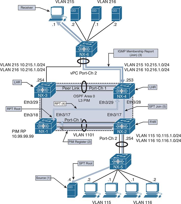
Figure 13-13 PIM ASM Topology
Figure 13-13 illustrates the following steps:
Step 1. Source 10.115.1.4 starts sending traffic to group 239.115.115.1. NX-2 receives the traffic and creates an (S,G) mroute entry for (10.115.1.4, 239.115.115.1).
Step 2. NX-2 registers the source with PIM RP NX-1 (10.99.99.1). The PIM RP creates an (S, G) mroute and sends a register-stop message in response. NX-2 continues to periodically send null register messages to the PIM RP as long as data traffic is arriving from the source.
Step 3. Receiver 10.215.1.1 sends an IGMP membership report to join 239.115.115.1. NX-4 receives the report. This results in a (*, G) mroute entry for (*, 239.115.115.1).
Step 4. NX-4 sends a PIM join to the PIM RP NX-1 and traffic arrives on the RPT.
Step 5. NX-4 receives traffic from the RPT and then switches to the SPT by sending a PIM join to NX-2. When NX-2 receives this PIM join message, an OIF for Eth3/17 is added to the (S,G) mroute entry.
Step 6. Although Figure 13-13 does not explicitly show it, NX-4 prunes itself from the RPT and traffic continues to flow from NX-2 on the SPT.
The order of these steps can vary if the receiver joins the RPT before the source is active, but the mentioned steps are required and still occur. Knowledge of these mandatory events can be combined with the mroute state on the FHR, LHR, PIM RP, and intermediate routers to determine exactly where the MDT is broken when a receiver is not getting traffic. It is important to remember that multicast state is created by control plane events in IGMP and PIM, as well as the receipt of multicast traffic in the data plane.
Note
The SPT switchover is optional in PIM ASM. The ip pim spt-threshold infinity command is used to force a device to remain on the RPT.
PIM ASM Configuration
The configuration for PIM ASM is straightforward. Each interface that is part of the multicast domain is configured with ip pim sparse-mode. This includes L3 interfaces between routers and any interface where receivers are connected. It is also considered a best practice to enable the PIM RP Loopback interface with ip pim sparse-mode for simplicity and consistency, although this might not be required on some platforms. The PIM RP address must be configured on every PIM router and must have a consistent mapping of groups to a particular RP address. NX-OS supports BSR and Auto-RP for automatically configuring the PIM RP address in the domain; this is covered in the “PIM RP Configuration” section of this chapter. Example 13-24 contains the PIM configuration for NX-1, which is currently acting as the PIM RP. The other PIM routers have a similar configuration but do not have a Loopback99 interface. Loopback99 is the interface where the PIM RP address is configured on NX-1. It is possible to configure multiple PIM RPs in the network and restrict which groups are mapped to a particular RP with the group-list or a prefix-list option.
Example 13-24 PIM ASM Configuration on NX-1
!Command: show running-config pim
feature pim
interface Vlan1101
ip pim sparse-mode
interface loopback99
ip pim sparse-mode
interface Ethernet3/17
ip pim sparse-mode
interface Ethernet3/18
ip pim sparse-mode
Depending on the scale of the network environment, it might be necessary to increase the size of the PIM event-history logs when troubleshooting a problem. The size is increased per event-history with the ip pim event-history [event type] size [event-history size] configuration command.
PIM ASM Verification
When troubleshooting a multicast routing problem with PIM ASM, it is generally best to start by verifying the multicast state at the LHR where the problematic receiver is attached. This is because determining the LHR has knowledge of the receiver from IGMP is critical. This step determines whether the problem is with L2 (IGMP) or L3 multicast routing (PIM). It also guides the next troubleshooting step to either the RPT or the SPT.
The presence of a (*, G) state at the LHR indicates that a receiver sent a valid membership report and the LHR sent an RPT join toward the PIM RP using the unicast route for the PIM RP to choose the interface. Note that the presence of a (*, G) indicates only a receiver sent a membership report, which might mean that the problematic receiver did not. Verify IGMP snooping forwarding tables for each switch that carries the VLAN to be sure that the receivers port is programmed for receiving the traffic. A receiver host or L2 forwarding problem can be confirmed if other receivers in the same VLAN can get the group traffic.
If the LHR has only a (*, G), it typically indicates that traffic is not arriving from the RPT. In that case, verify the mroute state between the LHR and the PIM RP and on any intermediate PIM routers along the tree. If the PIM RP has a valid OIF toward the LHR and packet counts are incrementing, a data plane problem might be keeping traffic from arriving at the LHR on the RPT, or the TTL of the packets might be expiring in transit. Tools such as Switch Port Analyzer (SPAN) capture, the ACL hit counter, or even the Embedded Logic Analyzer Module (ELAM) can isolate the problem to a specific device along the RPT.
After traffic arrives at the LHR on the RPT, it attempts to switch to the SPT. This step involves a routing table lookup for the source address to determine which PIM interface to send the SPT join message on. The LHR has (S, G) state for the SPT at this point with an OIL that contains the interface toward the receiver. The IIF for the SPT can be different than the IIF for the RPT, but it does not have to be.
The LHR sends a PIM SPT join toward the source. Each intermediate router along the path also has an (S, G) state with an OIF toward the LHR and an IIF toward the source for the SPT. At the FHR, the IIF is the interface where the source is attached and the OIF contains the interface on which the PIM SPT join was received, pointing in the direction of the LHR.
The same methodology can be used to troubleshoot multicast forwarding along the SPT. Determine whether any receivers, perhaps on another branch of the SPT, can receive traffic. Determine which device in the SPT is the merge point where the problem branch and working branch converge. The mroute state on that device should indicate that the interfaces for both branches are in the OIL. If they are not, verify PIM to determine why the SPT join was not received. If the OIL does contain both OIFs, the problem could be related to a data plane packet drop issue. In that case, SPAN, ACL, or ELAM is the best option to isolate the problem further. When the problem is isolated to a specific device along the tree, verify the control plane and platform-specific hardware forwarding entries to determine the root cause of the problem.
PIM ASM Event-History and MROUTE State Verification
The primary way to verify which PIM messages have been sent and received is to use the NX-OS event-history for PIM. This output adds debug-level visibility to the PIM process and messaging without any impact to the system resources. Figure 13-13 shows the topology used to examine the PIM messages and mroute state on each device when a new source becomes active and then when a receiver joins the group.
Source 10.115.1.4 begins sending traffic to 239.115.115.1, which arrives at NX-2 on VLAN 115. The receipt of this traffic causes an (S, G) mroute to be created (see Example 13-25). The ip flag on the mroute indicates that this state was created by receiving traffic.
Example 13-25 MROUTE State on NX-2 with Active Source
(10.115.1.4/32, 239.115.115.1/32), uptime: 00:00:04, ip pim
Incoming interface: Vlan115, RPF nbr: 10.115.1.4
Outgoing interface list: (count: 0)
NX-2 then registers this source with the PIM RP NX-1 (10.99.99.99) by sending a PIM register message with an encapsulated data packet from the source. NX-1 receives this register message, as the output of show ip pim internal event-history null-register in Example 13-26 shows. The first register message has pktlen 84, which creates the mroute state at the PIM RP. Subsequent null-register messages that do not have the encapsulated source packet are only 20 bytes. NX-1 responds to each register message with a register-stop.
Example 13-26 Register Message Received on NX-1
16:36:33.724154 pim [31641]::Send Register-Stop to 10.115.1.254 for
(10.115.1.4/32, 239.115.115.1/32)
16:36:33.724133 pim [31641]::Received NULL Register from 10.115.1.254
for (10.115.1.4/32, 239.115.115.1/32) (pktlen 20)
16:34:35.177572 pim [31641]::Send Register-Stop to 10.115.1.254
16:34:35.177398 pim [31641]::Received Register from 10.115.1.254 for
Note
NX-OS can have a separate event-history for receiving encapsulated data register messages, depending on the version. The command is show ip pim internal event-history data-register-receive. In older NX-OS releases, debug ip pim data-register send and debug ip pim data-register receive are used to debug the PIM registration process.
Because no receivers currently exist in the PIM domain, NX-1 adds an (S, G) mroute with an empty OIL (see Example 13-27). The IIF is the L3 interface between NX-1 and NX-2 Vlan1101, which is carried over Port-channel 1. The mroute has the PIM flag to indicate that PIM created this mroute state.
Example 13-27 MROUTE State on NX-1 with No Receivers
(10.115.1.4/32, 239.115.115.1/32), uptime: 00:00:09, pim ip
Incoming interface: Vlan1101, RPF nbr: 10.1.11.2, internal
Outgoing interface list: (count: 0)
After adding the mroute entry, NX-1 sends a register-stop message back to NX-2 (see Example 13-28). NX-2 suppresses its first null register message because it has just received a register-stop for a recent encapsulated data register message. After the register-stop, NX-2 starts its Register-Suppression timer. Just before expiring the timer, another null-register is sent. If the timer expires without a register stop from the RP, the DR resumes sending full encapsulated packets.
Example 13-28 Register-stop Message Received from NX-1
null-register events for PIM process
16:36:29.667674 pim [10076]::Received Register-Stop from 10.99.99.99 for
(10.115.1.4/32, 239.115.115.1/32)
16:36:29.666010 pim [10076]::Send Null Register to RP 10.99.99.99 for
(10.115.1.4/32, 239.115.115.1/32)
16:35:29.466161 pim [10076]::Suppress Null Register for
(10.115.1.4/32, 239.115.115.1/32) due to recent data Register sent
16:34:31.121180 pim [10076]::Received Register-Stop from 10.99.99.99 for
The source has been successfully registered with the PIM RP. This state persists until a receiver joins the group, with NX-2 periodically informing NX-1 via null register messages that the source is still actively sending to the group address.
A receiver in VLAN 215 connected to NX-4 sends a membership report to initiate the flow of multicast for the 239.115.115.1 group. When this message arrives at NX-4, it triggers the creation of a (*, G) mroute entry by IGMP with an OIL containing VLAN 215 (see Example 13-29). The IIF Ethernet 3/29 is the interface used to reach the PIM RP address on NX-1.
Example 13-29 MROUTE State on NX-4 with a Receiver
(*, 239.115.115.1/32), uptime: 00:01:12, igmp ip pim
Incoming interface: Ethernet3/29, RPF nbr: 10.2.13.1
Outgoing interface list: (count: 1)
Vlan215, uptime: 00:01:12, igmp
The mroute entry corresponds to a PIM RPT join being sent from NX-4 toward NX-1 (see Example 13-30).
Example 13-30 PIM RPT Join from NX-4 to NX-1
16:36:32.630489 pim [13449]::Put (*, 239.115.115.1/32), WRS in join-list for
When NX-1 receives this RPT Join from NX-4, the OIF Ethernet 3/17 is added to the OIL of the mroute (see Example 13-31).
Example 13-31 PIM RPT Join Received on NX-1
239.115.115.1
16:36:36.688652 pim [31641]::No (*, 239.115.115.1/32) route exists, to us
16:36:36.688643 pim [31641]::pim_receive_join: We are target comparing with iod
16:36:36.688604 pim [31641]::pim_receive_join: route: (*, 239.115.115.1/32),
wc_bit: TRUE, rp_bit: TRUE
16:36:36.688593 pim [31641]::Received Join-Prune from 10.2.13.3 on Ethernet3/17
length: 34, MTU: 9216, ht: 210
The receipt of the join triggers the creation of a (*, G) mroute state on NX-1 and also triggers a join from NX-1 to NX-2 over VLAN 1101 for the source (see Example 13-32).
Example 13-32 PIM Join Sent from NX-1 to NX-2
16:36:36.690481 pim [31641]::Send Join-Prune on Vlan1101, length: 34
16:36:36.690227 pim [31641]::Put (10.115.1.4/32, 239.115.115.1/32),
16:36:36.690158 pim [31641]::Put (10.115.1.4/32, 239.115.115.1/32),
RS in prune-list for nbr 10.99.99.99
16:36:36.690150 pim [31641]::wc_bit = FALSE, rp_bit = TRUE
16:36:36.690078 pim [31641]::(*, 239.115.115.1/32) we are RPF nbr
The result of this join from NX-1 to NX-2 is that NX-2 adds an OIF of VLAN 1101 (see Example 13-33).
Example 13-33 PIM Join Received from NX-1 on NX-2
RPF if Vlan115, to us
16:36:32.634186 pim [10076]::pim_receive_join: We are target comparing with iod
16:36:32.634142 pim [10076]::pim_receive_join: route:
(10.115.1.4/32, 239.115.115.1/32), wc_bit: FALSE, rp_bit: FALSE
16:36:32.634125 pim [10076]::Received Join-Prune from 10.1.11.1 on Vlan1101,
length: 34, MTU: 9216, ht: 210
Traffic now flows from the source, through NX-2 toward NX-1. NX-1 receives the traffic and forwards it through the RPT to NX-4. At NX-4, traffic is now received on the RPT and the SPT switchover occurs, as seen in the PIM event-history output in Example 13-34. NX-4 first sends the SPT join to NX-2 (10.2.23.2) and then prunes itself from the RPT to NX-1 (10.2.13.1).
Example 13-34 SPT Switchover on NX-4
16:36:33.256735 pim [13449]::Put (10.115.1.4/32, 239.115.115.1/32), RS in prune-list for nbr 10.2.13.1
16:36:33.256729 pim [13449]::wc_bit = FALSE, rp_bit = TRUE
16:36:33.255153 pim [13449]::Send Join-Prune on Ethernet3/28, length: 34 in context 1
16:36:33.253999 pim [13449]::Put (10.115.1.4/32, 239.115.115.1/32), S in join-list for nbr 10.2.23.2
16:36:33.253991 pim [13449]::wc_bit = FALSE, rp_bit = FALSE
The resulting mroute state on NX-4 is that the (S, G) was created and the OIL contains VLAN215. The IIF for the (S, G) points toward NX-2, while the IIF for the (*, G) points to the PIM RP at NX-1. Example 13-35 shows the show ip mroute output from NX-4.
Example 13-35 MROUTE State on NX-4 after SPT Switchover
(*, 239.115.115.1/32), uptime: 00:01:12, igmp ip pim
Incoming interface: Ethernet3/29, RPF nbr: 10.2.13.1
Outgoing interface list: (count: 1)
Vlan215, uptime: 00:01:12, igmp
(10.115.1.4/32, 239.115.115.1/32), uptime: 00:01:11, ip mrib pim
Incoming interface: Ethernet3/28, RPF nbr: 10.2.23.2
Outgoing interface list: (count: 1)
Vlan215, uptime: 00:01:11, mrib
NX-2 has an (S, G) mroute with the IIF of VLAN 115 and the OIF of Ethernet 3/17 that is connected to NX-4. Example 13-36 shows the mroute state of NX-2.
Example 13-36 MROUTE State on NX-2 after SPT Switchover
(10.115.1.4/32, 239.115.115.1/32), uptime: 00:03:09, ip pim
Incoming interface: Vlan115, RPF nbr: 10.115.1.4
Outgoing interface list: (count: 1)
Ethernet3/17, uptime: 00:01:07, pim
NX-1 has (*, G) state from NX-4 but no OIF for the (S, G) state. Example 13-37 contains the mroute table of NX-1 after the SPT switchover. The IIF of the (*, G) is the RP interface of Loopback99, which is the root of the RPT.
Example 13-37 MROUTE State on NX-1 after SPT Switchover
(*, 239.115.115.1/32), uptime: 03:34:42, pim ip
Incoming interface: loopback99, RPF nbr: 10.99.99.99
Outgoing interface list: (count: 1)
Ethernet3/17, uptime: 03:34:42, pim
(10.115.1.4/32, 239.115.115.1/32), uptime: 03:36:44, pim ip
Incoming interface: Vlan1101, RPF nbr: 10.1.11.2, internal
Outgoing interface list: (count: 0)
As the previous section demonstrates, the mroute state and the event-history in NX-OS make it possible to determine whether the problem involves the RPT or the SPT and to determine which device along the tree is causing trouble.
PIM ASM Platform Verification
During troubleshooting, verifying the hardware programming of a multicast routing entry might be necessary. This is required when the control plane PIM messages and the mroute table indicate that packets should be leaving an interface, but the downstream PIM neighbor is not receiving the traffic.
An example verification is provided here for reference using NX-2, which is a Nexus 7700 with an F3 module. The verification steps provided here are similar on other NX-OS platforms until the Input/Output (I/O) module is reached. When troubleshooting reaches that level, the verification commands vary significantly, depending on the platform.
The platform-independent (PI) components, such as the mroute table, the mroute table clients (PIM, IGMP, and MSDP), and the Multicast Forwarding Distribution Manager (MFDM), are similar across NX-OS platforms. The way that those entries get programmed into the forwarding and replication ASICs varies. Troubleshooting to the ASIC programming level is best left to Cisco TAC because it is easy to misinterpret the information presented in the output without a firm grasp on the platform-dependent (PD) architecture.
Verify the current mroute state as shown in Example 13-38.
Example 13-38 MROUTE Verification on NX-2
(10.115.1.4/32, 239.115.115.1/32), uptime: 00:00:31, ip pim
Incoming interface: Vlan115, RPF nbr: 10.115.1.4
Outgoing interface list: (count: 1)
Ethernet3/17, uptime: 00:00:31, pim
The mroute provides the IIF and OIF, dictating which modules need to be verified. Knowing which modules are involved is important because the Nexus 7000 series performs egress replication for multicast traffic. With egress replication, packets arrive on the ingress module and a copy of the packet is sent to any local receivers on the same I/O module. Another copy of the packet is directed to the fabric toward the I/O module of the interfaces in the OIL of the mroute. When the packet arrives at the egress module, another lookup is done to replicate the packet to the egress interfaces.
The OIL contains L3 interface Ethernet 3/17, and the IIF is VLAN 115. To confirm which physical interface the traffic is arriving on in VLAN 115, the ARP cache and MAC address table entries are checked for the multicast source. The show ip arp command provides the MAC address of the source (see Example 13-39).
Example 13-39 ARP Entry for the Multicast Source
Flags: * - Adjacencies learnt on non-active FHRP router
+ - Adjacencies synced via CFSoE
# - Adjacencies Throttled for Glean
D - Static Adjacencies attached to down interface
IP ARP Table
Total number of entries: 1
Address Age MAC Address Interface
Now check the MAC address table to confirm which interface packets should be arriving on from 10.115.1.4. Example 13-40 shows the output of the MAC address table.
Example 13-40 MAC Address Table Entry for the Multicast Source
Note: MAC table entries displayed are getting read from software.
Use the 'hardware-age' keyword to get information related to 'Age'
Legend:
* - primary entry, G - Gateway MAC, (R) - Routed MAC, O - Overlay MAC
age - seconds since last seen,+ - primary entry using vPC Peer-Link, E -
EVPN entry
(T) - True, (F) - False , ~~~ - use 'hardware-age' keyword to retrieve
age info
VLAN/BD MAC Address Type age Secure NTFY Ports/SWID.SSID.LID
---------+-----------------+--------+---------+------+----+------------------
* 115 64a0.e73e.12c2 dynamic ~~~ F F Eth3/19
It has now been confirmed that packets are coming into NX-2 on Ethernet 3/19 and egressing on Ethernet 3/17 toward NX-4. The next step in the verification is to check the MFDM entry for the group to ensure that it is present with the correct IIF and OIL (see Example 13-41).
Example 13-41 MFDM Verification on NX-2
(10.115.1.4/32, 239.115.115.1/32), RPF Interface: Vlan115, flags:
Received Packets: 18 Bytes: 1862
Number of Outgoing Interfaces: 1
The MFDM entry looks correct. The remaining steps are performed from the LC console, which is accessed with the attach module [module number] command. If the verification is being done in a nondefault VDC, it is important to use the vdc [vdc number] command to enter the correct context after logging into the module. After logging into the correct ingress module, confirm the correct L3LKP ASIC.
Note
Verification can be completed without logging into the I/O module by using the slot [module number] quoted [LC CLI command] to obtain output from the module.
The F3 module uses a switch-on-chip (SOC) architecture, where groups of front panel ports are serviced by a single SOC. Example 13-42 demonstrates this mapping with the show hardware internal dev-port-map command.
Example 13-42 Determining the SoC Instances on Module 3 of NX-2
To exit type 'exit', to abort type '$.'
module-3# show hardware internal dev-port-map
--------------------------------------------------------------
CARD_TYPE: 48 port 10G
>Front Panel ports:48
--------------------------------------------------------------
Device name Dev role Abbr num_inst:
--------------------------------------------------------------
> Flanker Eth Mac Driver DEV_ETHERNET_MAC MAC_0 6
> Flanker Fwd Driver DEV_LAYER_2_LOOKUP L2LKP 6
> Flanker Xbar Driver DEV_XBAR_INTF XBAR_INTF 6
> Flanker Queue Driver DEV_QUEUEING QUEUE 6
> Sacramento Xbar ASIC DEV_SWITCH_FABRIC SWICHF 1
> Flanker L3 Driver DEV_LAYER_3_LOOKUP L3LKP 6
> EDC DEV_PHY PHYS 7
+-----------------------------------------------------------------------+
+----------------+++FRONT PANEL PORT TO ASIC INSTANCE MAP+++------------+
+-----------------------------------------------------------------------+
FP port | PHYS | MAC_0 | L2LKP | L3LKP | QUEUE |SWICHF
17 2 2 2 2 2 0
18 2 2 2 2 2 0
19 2 2 2 2 2 0
20 2 2 2 2 2 0
21 2 2 2 2 2 0
In this particular scenario, the ingress port and egress port are using the same SOC instance (2), and are on the same module. If the module or SOC instance were different, each SOC on each module would need to be verified to ensure that the correct information is present.
With the SOC numbers confirmed for the ingress and egress interfaces, now check the forwarding entry on the I/O module. This entry has the correct incoming interface of Vlan115 and the correct OIL, which contains Ethernet 3/17 (see Example 13-43). Verify the outgoing packets counter to ensure that it is incrementing periodically.
Example 13-43 I/O Module MFIB Verification on Module 3
(10.115.1.4/32, 239.115.115.1/32), RPF Interface: Vlan115, flags:
Received Packets: 1149 Bytes: 117224
Number of Outgoing Interfaces: 2
Outgoing Interface List Index: 31
Vlan1101 Outgoing Packets:0 Bytes:0
All information so far has the correct IIF and OIF, so the final step is to check the programming from the SOC (see Example 13-44).
Example 13-44 Hardware Forwarding Verification on Module 3
group 239.115.115.1 detail
Flags Legend:
* - s_star_priority
S - sg_entry
D - Non-RPF Drop
B - Bi-dir route W - Wildcard route
(10.115.1.4/32, 239.115.115.1/32), Flags: *S
Dev: 2, HWIndex: 0x6222 Priority: 0x4788, VPN/Mask: 0x1/0x1fff
RPF Interface: Vlan115, LIF: 0x15
MD Adj Idx: 0x5c, MDT Idx: 0x1, MTU Idx: 0x0, Dest Idx: 0x2865
PD oiflist Idx: 0x1, EB MET Ptr: 0x1
Dev: 2 Index: 0x70 Type: OIF elif: 0x5 Ethernet3/17
Dest Idx: 0x10 SMAC: 64a0.e73e.12c1
module-3#
Cisco TAC should interpret the various fields present. These fields represent the pointers to the various table lookups required to replicate the multicast packet locally, or to the fabric if the egress interface is on a different module or SOC. Verification of these indexes requires multiple ELAM captures at the various stages of forwarding lookup and replication.
PIM Bidirectional
PIM BiDIR is another version of PIM SM in which several modifications to traditional ASM behavior have been made. The differences between PIM ASM and PIM BiDIR follow:
BiDIR uses bidirectional shared trees, whereas ASM relies on unidirectional shared and source trees.
BiDIR does not use any (S, G) state. ASM must maintain (S, G) state for every source sending traffic to a group address.
BiDIR does not need any source registration process, which reduces processing overhead.
Both ASM and BiDIR must have every group mapped to a rendezvous point (RP). The RP in BiDIR does not actually do any packet processing. In BiDIR, the RP address (RPA) is just a route vector that is used as a reference point for forwarding up or down the shared tree.
BiDIR uses the concept of a Designated Forwarder (DF) that is elected on every link in the PIM domain.
Because BiDIR does not require any (S, G) state, only a single (*, G) mroute entry is required to represent a group. This can dramatically reduce the number of mroute entries in a network with many sources, compared to ASM. With a reduction of mroute entries, the potential scalability of the network is higher because any router platform has a finite number of table entries that can be stored before resources become exhausted. The increase in scale does come with a trade-off of losing visibility into the traffic of individual sources because there is no (S, G) state to track them. However, in very large, many-to-many environments, this downside is outweighed by the reduction in state and the elimination of the registration process.
BiDIR has important terminology that must be defined before looking further into how it operates. Table 13-10 provides these definitions.
Table 13-10 PIM BiDIR Terminology
Term |
Definition |
Rendezvous point address (RPA) |
An address that is used as the root of the MDT for all groups mapped to it. The RPA must be reachable from all routers in the PIM domain. The address used for the RPA does not need to be configured on the interface of any router in the PIM domain. |
Rendezvous point link (RPL) |
The physical link used to reach the RPA. All packets for groups mapped to the RPA are forwarded out of the RPL. The RPL is the only interface where a DF election does not occur. |
Designated forwarder (DF) |
A single DF is elected on every link for each RPA. The DF is elected based on its unicast routing metric to the RPA. The DF is responsible for sending traffic down the tree to its link and is also responsible for sending traffic from its link upstream toward the RPA. In addition, the DF is responsible for sending PIM Join-Prune messages upstream toward the RPA, based on the state of local receivers or PIM neighbors. |
RPF interface |
The interface used to reach an address, based on unicast routing protocol metrics. |
RPF neighbor |
The PIM neighbor used to reach an address, based on the unicast routing protocol metrics. With BiDIR, the RPF neighbor might not be the router that should receive Join-Prune messages. All Join-Prune messages should be directed to the elected DF. |
PIM neighbors that can understand BiDIR set the BiDIR capable bit in their PIM hello messages. This is a foundational requirement for BiDIR to become operational. As the PIM process becomes operational on each router, the group-to-RP mapping table is populated by either static configuration or through Auto-RP or BSR. When the RPA(s) are known, the router determines its unicast routing metric for the RPA(s) and moves to the next phase, to elect the DF on each interface.
Initially, all routers begin sending PIM DF election messages that carry the offer subtype. The offer message contains the sending router’s unicast routing metric to reach the RPA. As these messages are exchanged, all routers on the link become aware of each other and what each router’s metric is to the RPA. If a router receives an offer message with a better metric, it stops sending offer messages, to allow the router with the better metric to become elected as the DF. However, if the DF election does not occur, the election process restarts. The result of this initial DF election should be that all routers except for the one with the best metric stop sending offer messages. This allows the router with the best metric to assume the DF role after sending three offers and not receiving additional offers from any other neighbor. After assuming the DF role, the router transmits a DF election message with the winner subtype, which tells all routers on the link which device is the DF and informs them of the winning metric.
During normal operation, a new router might come online or metrics toward the RPA could change. This essentially results in offer messages sent to the current DF. If the current DF still has the best metric to the RPA, it responds with a winner message. If the received metric is better than the current DF, the current DF sends a backoff message. The backoff message tells the challenging router to wait before assuming the DF role so that all routers on the link have an opportunity to send an offer message. During this time, the original DF is still acting as the DF. After the new DF is elected, the old DF transmits a DF election message with the pass subcode, which hands over the DF responsibility to the new winner. After the DF is elected, the PIM BiDIR network is ready to begin forwarding multicast packets bidirectionally using shared trees rooted at the RPA.
Packets arriving from a downstream link are forwarded upstream until they reach the router with the RPL, which contains the RPA. Because no registration process occurs and no switchover to an SPT takes place, the RPA does not need to be on a router. This is initially confusing, but it works because packets are forwarded out the RPL toward the RPA, and (*, G) state is built from every FHR connected to a source and from every LHR with an interested receiver toward the RPA. In other words, with BiDIR, packets do not have to actually traverse the RP as they do in ASM. The intersecting branches of the bidirectional (*, G) tree can distribute multicast directly between source and receiver.
In NX-OS, up to eight BiDIR RPAs are supported per VRF. Redundancy for the RPA is achieved using a concept referred to as a phantom RP. The term is used because the RPA is not assigned to any router in the PIM domain. For example, assume an RPA address of 10.1.1.1. NX-1 could have 10.1.1.0/30 configured on its Loopback10 interface and NX-3 could have 10.1.1.0/29 configured on its Loopback10 interface. All routers in the PIM domain follow the longest-prefix-match rule in their routing table to prefer NX-1. If NX-1 failed, NX-3 would then become the preferred path to the RPL and thus the RP as soon as the unicast routing protocol converges.
The topology in Figure 13-14 demonstrates the configuration and troubleshooting of PIM BiDIR.
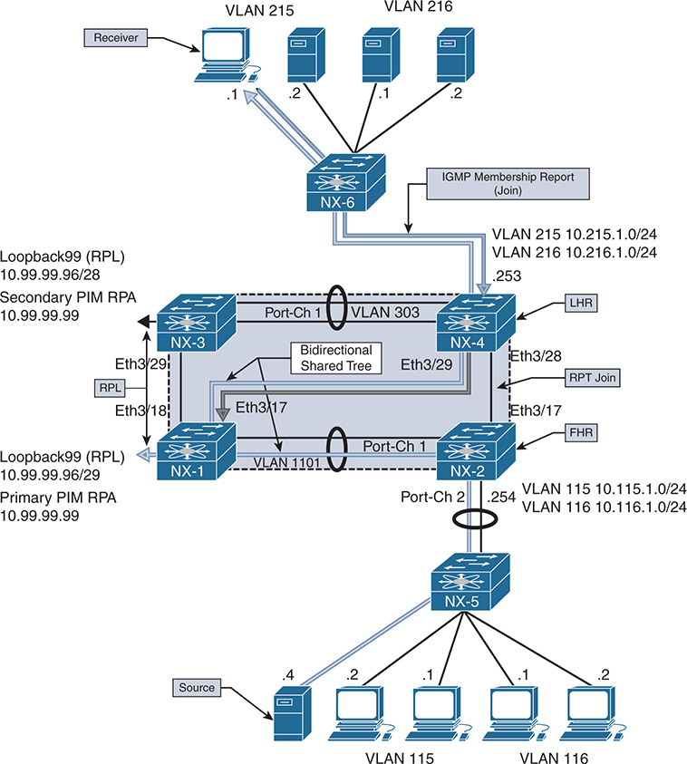
Figure 13-14 PIM BiDIR Topology
When a receiver attached to VLAN 215 on NX-4 joins 239.115.115.1, a (*, G) mroute entry is created on NX-4. On the link between NX-4 and NX-1, NX-1 is the elected DF because it has a better unicast metric to the RPA. Therefore the (*, G) join from NX-4 is sent to NX-1 upstream toward the primary RPA.
NX-1 and NX-3 are both configured with a link (Loopback99) to the phantom RP 10.99.99.99. However, NX-1 has a more specific route to the RPA through its RPL and is used by all routers in the topology to reach the RPA.
When 10.115.1.4 begins sending multicast traffic to 239.115.115.1, the traffic arrives on VLAN 115 on NX-2. Because NX-2 is the elected DF on VLAN 115, the traffic is forwarded upstream toward the RPA on its RPF interface, VLAN 1101. NX-1 is the elected DF for VLAN 1101 between NX-2 and NX-1 because it has a better metric to the RPA. NX-1 receives the traffic from NX-2 and forwards it based on the current OIL for its (*, G) mroute entry. The OIL contains both the Ethernet 3/17 link to NX-4 and also the Loopback99 interface with is the RPL. As traffic flows from the source to the receiver, the shared tree is used end to end, and NX-4 never uses the direct link it has to NX-2 because no SPT switchover takes place with BiDIR. No source needs to be registered with a PIM RP and no (S, G) state needs to be created because all traffic for the group flows along the shared tree.
BiDIR Configuration
The configuration for PIM BiDIR is similar to the configuration of PIM ASM. PIM sparse mode must be enabled on all interfaces. The BiDIR capable bit is set in PIM hello messages by default, so no interface-level command is required to specifically enable PIM BiDIR. An RP is designated as a BiDIR RPA when it is configured with the bidir keyword in the ip pim rp-address [RP address] group-range [groups] bidir command.
Example 13-45 shows the phantom RPA configuration that was previously described. Loopback99 is the RPL, which is configured with a subnet that contains the RPA. The RPA is not actually configured on any router in the topology, which is a major difference between PIM BiDIR and PIM ASM. This RPA is advertised to the PIM domain with OSPF; because you want OSPF to advertise the link as 10.99.99.96/29, the ip ospf network point-to-point command is used. This forces OSPF on NX-1 to advertise this as a stub-link in the type 1 router link-state advertisement (LSA).
Example 13-45 PIM BiDIR Configuration on NX-1
feature pim
ip pim rp-address 10.99.99.99 group-list 224.0.0.0/4 bidir
ip pim ssm range 232.0.0.0/8
interface Vlan1101
ip pim sparse-mode
interface loopback0
ip pim sparse-mode
interface loopback99
ip pim sparse-mode
interface Ethernet3/17
ip pim sparse-mode
interface Ethernet3/18
ip pim sparse-mode
NX-1# show run interface loopback99
!Command: show running-config interface loopback99
interface loopback99
ip address 10.99.99.98/29
PIM Group-Range Configuration for VRF "default"
Group-range Action Mode RP-address Shrd-tree-range Origin
224.0.0.0/4 - Bidir 10.99.99.99 - Static NX-1# show ip pim rp
PIM RP Status Information for VRF "default"
BSR disabled
Auto-RP disabled
BSR RP Candidate policy: None
BSR RP policy: None
Auto-RP Announce policy: None
Auto-RP Discovery policy: None
RP: 10.99.99.99, (1),
uptime: 22:29:39 priority: 0,
RP-source: (local),
group ranges:
Note
All other routers in the topology have the same BiDIR-specific configuration, which is the static RPA with the BiDIR keyword. NX-1 and NX-3 are the only routers configured with an RPL to the RPA.
BiDIR Verification
To understand the mroute state and BiDIR events, verification begins from NX-4, where a receiver is connected in VLAN 215. Example 13-46 gives the output of show ip mroute from NX-4, which is the LHR. The (*, G) mroute was created as a result of the IGMP membership report from the receiver. Because this is a bidirectional shared tree, notice that the RPF interface Ethernet 3/29 used to reach the RPA is also included in the OIL for the mroute.
Example 13-46 PIM BiDIR MROUTE Entry on NX-4
(*, 224.0.0.0/4), bidir, uptime: 00:06:39, pim ip
Incoming interface: Ethernet3/29, RPF nbr: 10.2.13.1
Outgoing interface list: (count: 1)
Ethernet3/29, uptime: 00:06:39, pim, (RPF)
(*, 239.115.115.1/32), bidir, uptime: 00:04:08, igmp ip pim
Incoming interface: Ethernet3/29, RPF nbr: 10.2.13.1
Outgoing interface list: (count: 2)
The DF election process in BiDIR determines which PIM router on each interface is responsible for sending join-prune messages and routing packets from upstream to downstream and vice versa on the bidirectional shared tree. The output of show ip pim df provides a concise view of the current DF state on each PIM-enabled interface (see Example 13-47). On VLAN 215, this router is the DF; on the RPF interface toward the RPA, this router is not the DF because the peer has a better metric to the RPA.
Example 13-47 PIM BiDIR DF Status on NX-4
RP Address (ordinal) RP Metric Group Range
10.99.99.99 (1) [110/5] 224.0.0.0/4
Interface DF Address DF State DF Metric DF Uptime
Vlan303 10.2.33.2 Winner [110/5] 00:22:28
Vlan216 10.216.1.254 Loser [110/5] 00:22:29
Eth3/28 10.2.23.2 Loser [110/2] 00:22:29
If additional detail is needed about the BiDIR DF election process, the output of show ip pim internal event-history bidir provides information on the interface state machine and its reaction to the received PIM DF election messages. Example 13-48 shows the event-history output from NX-4. The DF election is seen for VLAN 215; no other offers are received and NX-4 becomes the winner. On Ethernet 3/29, NX-4 (10.2.13.3) has a worse metric (-1/-1) than the current DF (10.2.13.1) and does not reply with an offer message. This allows NX-1 to become the DF on this interface.
Example 13-48 PIM BiDIR Event-History on NX-4
bidir events for PIM process
20:32:46.269627 pim [10572]:: pim_update_df_state: vrf: default: rp:
10.99.99.99 iod Ethernet3/29 prev_state 2 Notify IGMP
20:32:46.269623 pim [10572]:: Entering Lose state on Ethernet3/29
20:32:46.269439 pim [10572]:: pim_update_df_state: vrf: default: rp:
Bidir-RP Ordinal:1, DF-interfaces: 00000000
20:32:40.205947 pim [10572]:: pim_df_expire_timer: Entering Winner state
Because NX-4 is the DF election winner on VLAN 215, it sends a PIM join for the shared tree to the DF on the RPF interface Ethernet 3/29. The show ip pim internal event-history join-prune command is used to view these events (see Example 13-49 for the output).
Example 13-49 PIM BiDIR Join-prune Event-History on NX-4
join-prune events for PIM process
20:34:34.286181 pim [10572]:: Keep bidir (*, 239.115.115.1/32) entry alive due
to joined oifs exist
20:33:40.056128 pim [10572]: [10739]: skip sending periodic join not having
any oif
20:33:40.056116 pim [10572]:: Keep bidir (*, 224.0.0.0/4) prefix-entry alive
20:33:34.016224 pim [10572]:: Send Join-Prune on Ethernet3/29, length:
34 in context 1
20:33:34.016186 pim [10572]:: Put (*, 239.115.115.1/32), WRS in join-list for
nbr 10.2.13.1
20:33:34.016179 pim [10572]:: wc_bit = TRUE, rp_bit = TRUE
In addition to the detailed information in the event-history output, the interface statistics can be checked to view the total number of BiDIR messages that were exchanged (see Example 13-50).
Example 13-50 PIM BiDIR Interface Counters on NX-4
PIM Interface Status for VRF "default"
Ethernet3/29, Interface status: protocol-up/link-up/admin-up
IP address: 10.2.13.3, IP subnet: 10.2.13.0/24
PIM DR: 10.2.13.3, DR's priority: 1
PIM neighbor count: 1
PIM hello interval: 30 secs, next hello sent in: 00:00:22
PIM neighbor holdtime: 105 secs
PIM configured DR priority: 1
PIM configured DR delay: 3 secs
PIM border interface: no
PIM GenID sent in Hellos: 0x140c2403
PIM Hello MD5-AH Authentication: disabled
PIM Neighbor policy: none configured
PIM Join-Prune inbound policy: none configured
PIM Join-Prune outbound policy: none configured
PIM Join-Prune interval: 1 minutes
PIM Join-Prune next sending: 0 minutes
PIM BFD enabled: no
PIM passive interface: no
PIM VPC SVI: no
PIM Auto Enabled: no
PIM Interface Statistics, last reset: never
General (sent/received):
Hellos: 4880/2121 (early: 0), JPs: 378/0, Asserts: 0/0
Grafts: 0/0, Graft-Acks: 0/0
Checksum errors: 0, Invalid packet types/DF subtypes: 0/0
Authentication failed: 0
Packet length errors: 0, Bad version packets: 0, Packets from self: 0
Packets from non-neighbors: 0
Packets received on passiveinterface: 0
JPs received on RPF-interface: 0
(*,G) Joins received with no/wrong RP: 0/0
(*,G)/(S,G) JPs received for SSM/Bidir groups: 0/0
JPs filtered by inbound policy: 0
JPs filtered by outbound policy: 0
The next hop in the bidirectional shared tree is NX-1, which is NX-4’s RPF neighbor to the RPA. The join-prune event-history confirms that the (*, G) join was received from NX-4 (see Example 13-51).
Example 13-51 PIM BiDIR Join-Prune Event-History on NX-1
bidir events for PIM process
20:33:34.020037 pim [7851]:: -----
20:33:34.020020 pim [7851]:: (*, 239.115.115.1/32) route exists, RPF if
loopback99, to us
20:33:34.020008 pim [7851]:: pim_receive_join: We are target comparing with iod
20:33:34.019968 pim [7851]:: pim_receive_join: route: (*, 239.115.115.1/32),
wc_bit: TRUE, rp_bit: TRUE
20:33:34.019341 pim [7851]:: Received Join-Prune from 10.2.13.3 on
The mroute state for NX-1 contains Ethernet3/17 as well as Loopback99, which is the RPL in Example 13-52. All groups that map to the RPA are forwarded on the RPL toward the RPA.
Example 13-52 PIM BiDIR MROUTE Entry on NX-1
IP Multicast Routing Table for VRF "default"
(*, 224.0.0.0/4), bidir, uptime: 00:13:22, pim ip
Incoming interface: loopback99, RPF nbr: 10.99.99.99
Outgoing interface list: (count: 1)
loopback99, uptime: 00:13:22, pim, (RPF)
(*, 239.115.115.1/32), bidir, uptime: 00:14:13, pim ip
Incoming interface: loopback99, RPF nbr: 10.99.99.99
Outgoing interface list: (count: 2)
Example 13-53 gives the output of show ip pim df. Because the RPL is local to this device, it is the DF winner on all interfaces except for the RPL. No DF is elected on the RPL in PIM BiDIR.
Example 13-53 PIM DF Status on NX-1
RP Address (ordinal) RP Metric Group Range
10.99.99.99 (1) [0/0] 224.0.0.0/4
Interface DF Address DF State DF Metric DF Uptime
Vlan1101 10.1.11.1 Winner [0/0] 00:14:43
Po3 10.1.12.2 Winner [0/0] 00:14:43
Lo0 10.1.1.1 Winner [0/0] 00:14:43
Eth3/18 10.1.13.1 Winner [0/0] 00:14:43
No (S, G) join exists from the RPA toward the source as there would have been in PIM ASM. In BiDIR, all traffic from the source is forwarded from NX-2, which is the FHR toward the RPA. Therefore, a join from NX-1 to NX-2 is not required to pull the traffic to NX-1 across VLAN1101. This fact highlights one troubleshooting disadvantage of BiDIR. No visibility from the RPA to the FHR is available about this particular source because the (S, G) state does not exist.
An ELAM capture can be used on NX-1 to verify that traffic is arriving from NX-2. Another useful technique is to configure a permit line in an ACL to match the traffic. Configure the ACL with statistics per-entry, which provides a counter to verify that traffic has arrived. In the output of Example 13-54, the ACL named verify was configured to match the source connected on NX-2. The ACL is applied ingress on VLAN 1101, which is the interface traffic should be arriving on.
Example 13-54 ACL to Match Traffic on NX-1
NX-1# show running-config interface Vlan1101
interface Vlan1101
description L3 to 7009-B-NX-2
no shutdown
mtu 9216
ip address 10.1.11.1/30
no ipv6 redirects
ip ospf cost 1
ip router ospf 1 area 0.0.0.0
ip pim sparse-mode
NX-1# show access-list verify
IP access list verify
statistics per-entry
In this exercise, the source is connected to NX-2, so the mroute entry can be verified to ensure that VLAN 1101 to NX-1 is included in the OIL. Example 13-55 shows the mroute from NX-2. The mroute entry covers all groups mapped to the RPA.
Example 13-55 PIM BiDIR MROUTE Entry on NX-2
RP Address (ordinal) RP Metric Group Range
10.99.99.99 (1) [110/2] 224.0.0.0/4
Interface DF Address DF State DF Metric DF Uptime
Eth3/18 10.1.23.2 Winner [110/2] 00:08:48
NX-2# show ip mroute
IP Multicast Routing Table for VRF "default"
(*, 224.0.0.0/4), bidir, uptime: 2d12h, pim ip
Incoming interface: Vlan1101, RPF nbr: 10.1.11.1
Outgoing interface list: (count: 1)
Because NX-2 is the DF winner on VLAN 115, it is responsible for forwarding multicast traffic from VLAN 115 toward the RPF interface for the RPA that is on VLAN 1101. With BiDIR, NX-2 has no need to register its source with the RPA; it simply forwards traffic from VLAN 115 up the bidirectional shared tree.
This section explained PIM BiDIR and detailed how to confirm the DF and mroute entries at each multicast router participating in the bidirectional shared tree. BiDIR and ASM have several differences with respect to multicast state and forwarding behavior. When faced with troubleshooting a BiDIR problem, it is important to know which RPA should be used for the group and which devices along the tree are functioning as the DR. It should then be possible to trace from the receiver toward the source and isolate the problem to a particular device along the path.
PIM RP Configuration
When PIM SM is configured for ASM or BiDIR, each multicast group must map to a PIM RP address. This mapping must be consistent in the network, and each router in the PIM domain must know the RP address–to–group mapping. Three options are available for configuring the PIM RP address in a multicast network:
Static PIM RP: The RP-to-group mapping is configured on each router statically.
Auto-RP: PIM RPs announce themselves to a mapping agent. The mapping agent advertises the RP to group mapping to all routers in the PIM domain. Cisco created Auto-RP before the PIM BSR mechanism was standardized.
BSR: Candidate RPs announce themselves to the bootstrap router. The bootstrap router advertises the group to RP mapping in a bootstrap message to all routers in the PIM domain.
Static RP Configuration
Static RP is the simplest mechanism to implement. Each router in the domain is configured with a PIM RP address, as shown in Example 13-56.
Example 13-56 PIM Static RP on NX-3 Configuration Example
!Command: show running-config pim
feature pim
interface Vlan215
ip pim sparse-mode
interface Vlan216
ip pim sparse-mode
interface Vlan303
ip pim sparse-mode
interface Ethernet3/28
ip pim sparse-mode
interface Ethernet3/29
ip pim sparse-mode
The simplicity has drawbacks, however. Any change to the group mapping requires the network operator to update the configuration on each router. In addition, a single static PIM RP could become a scalability bottleneck as hundreds or thousands of sources are being registered. If the network is small in scale, or if a single PIM RP address is being used for all groups, a static RP could be a good option.
Note
If a static RP is configured and dynamic RP–to–group mapping is received, the router uses the dynamic learned address if it is more specific. If the group mask length is equal, the higher IP address is used. The override keyword forces a static RP to win over Auto-RP or BSR.
Auto-RP Configuration and Verification
Auto-RP uses the concept of candidate RPs and candidate mapping agents. Candidate RPs send their configured multicast group ranges in RP-announce messages that are multicast to 224.0.1.39. Mapping agents listen for the RP-announce messages and collect the RP-to-group mapping data into a local table. After resolving any conflict in the mapping, the list is passed to the network using RP-discovery messages that are sent to multicast address 224.0.1.40. Routers in the network are configured to listen for the RP-discovery messages sent by the elected mapping agent. Upon receiving the RP-discovery message, each router in the PIM domain updates its local RP-to-group mapping table.
Multiple mapping agents could exist in the network, so a deterministic method is needed to determine which mapping agent routers should listen to. Routers in the network use the mapping agent with the highest IP address to populate their group-to-RP mapping tables. See Figure 13-15 for the topology used here to discuss the operation and verification of Auto-RP.
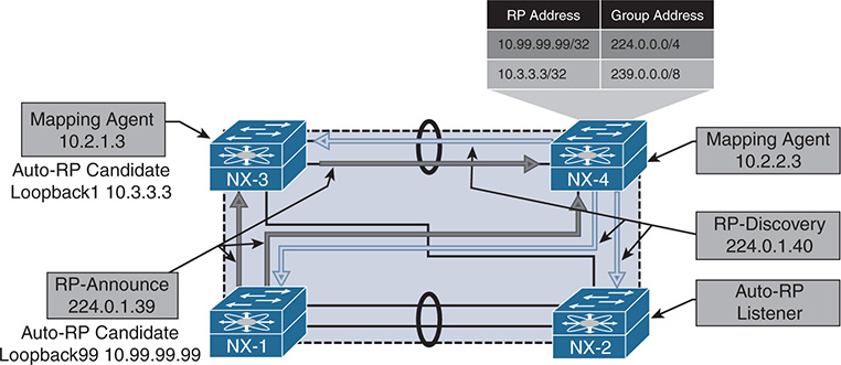
Figure 13-15 PIM Auto-RP Topology
In the topology in Figure 13-15, NX-1 is configured to send RP-announce messages for 224.0.0.0/4 with RP address 10.99.99.99. NX-3 is configured to send RP-announce messages for 239.0.0.0/8 with RP address 10.3.3.3. NX-3 is also configured as an Auto-RP mapping agent with address 10.2.1.3. NX-4 is configured as an Auto-RP mapping agent with address 10.2.2.3, and NX-2 is simply listening for Auto-RP discovery messages to populate the local RP-to-group mapping information. This example was built to illustrate the fact that multiple candidate RPs (and multiple mapping agents) can coexist.
When the PIM domain has overlapping or conflicting information, such as two candidate RPs announcing the same group, the mapping agent must decide which RP is advertised in the RP-discovery messages. The tie-breaking rule is as follows:
Choose the RP announcing the more specific group address.
If the groups are announced with an equal number of mask bits, choose the RP with the higher IP address.
In the example here, NX-3 is announcing a more specific advertisement of 239.0.0.0/8 versus the NX-1 advertisement of 224.0.0.0/4. The resulting behavior is that NX-3 is chosen as the RP for 239.0.0.0/8 groups, and NX-1 is chosen for all other groups. If multiple Auto-RP mapping agents are configured, NX-OS will choose to listen to RP-discovery messages from the mapping agent with the higher IP address.
Example 13-57 shows the PIM configuration for NX-1. The ip pim auto-rp rp-candidate command configures NX-1 to send Auto-RP RP-announce messages with a TTL of 16 for all multicast groups. NX-OS does not listen to or forward Auto-RP messages by default. The ip pim auto-rp forward listen command instructs the device to listen for and forward the Auto-RP groups 224.0.1.39 and 224.0.1.40. The local PIM RP-to-group mapping is shown with the show ip pim rp command. It displays the current group mapping for each RP, along with the RP-source, which is the mapping agent NX-4 (10.2.2.3).
Example 13-57 PIM Auto-RP Candidate-RP Configuration on NX-1
!Command: show running-config pim
feature pim
ip pim rp-address 10.99.99.99 group-list 224.0.0.0/4
interface Vlan1101
ip pim sparse-mode
interface loopback99
ip pim sparse-mode
interface Ethernet3/17
ip pim sparse-mode
interface Ethernet3/18
ip pim sparse-mode
NX-1# show ip pim rp
PIM RP Status Information for VRF "default"
BSR disabled
Auto-RP RPA: 10.2.2.3, uptime: 00:55:41, expires: 00:02:28
BSR RP Candidate policy: None
BSR RP policy: None
Auto-RP Announce policy: None
Auto-RP Discovery policy: None
The group range can be configured for additional granularity using the group-list, prefix-list, or route-map options.
Note
The interface used as an Auto-RP candidate-RP or mapping agent must be configured with ip pim sparse-mode.
Example 13-58 shows the Auto-RP mapping agent configuration from NX-4. This configuration results in NX-4 sending RP-discovery messages with a TTL of 16. In the output of show ip pim rp, because NX-4 is the current mapping agent, a timer is displayed to indicate when the next RP-discovery message will be sent.
Example 13-58 Auto-RP Mapping Agent Configuration on NX-4
!Command: show running-config pim
feature pim
ip pim sparse-mode
interface Vlan216
ip pim sparse-mode
interface Vlan303
ip pim sparse-mode
interface loopback0
ip pim sparse-mode
interface Ethernet3/28
ip pim sparse-mode
interface Ethernet3/29
ip pim sparse-mode
NX-4# show ip pim rp
PIM RP Status Information for VRF "default"
BSR disabled
Auto-RP RPA: 10.2.2.3*, next Discovery message in: 00:00:29
BSR RP Candidate policy: None
BSR RP policy: None
Auto-RP Announce policy: None
Auto-RP Discovery policy: None
Note
Do not use an anycast IP address for the mapping agent address. This could result in frequent refreshing of the RP mapping in the network.
NX-3 is configured to act as both an Auto-RP candidate RP and a mapping agent. Example 13-59 shows the configuration for NX-3. Note that the interface Loopback0 is being used as the mapping agent address, and Loopback1 is being used as the candidate-rp address; both are configured with ip pim sparse-mode.
Example 13-59 Auto-RP Configuration on NX-3
!Command: show running-config pim
feature pim
ip pim rp-address 10.3.3.3 group-list 239.0.0.0/8
interface Vlan215
ip pim sparse-mode
interface Vlan216
ip pim sparse-mode
interface Vlan303
ip pim sparse-mode
interface loopback0
ip pim sparse-mode
interface loopback1
ip pim sparse-mode
interface Ethernet3/28
ip pim sparse-mode
interface Ethernet3/29
ip pim sparse-mode
NX-3# show ip pim rp
PIM RP Status Information for VRF "default"
BSR disabled
Auto-RP RPA: 10.2.2.3, uptime: 01:21:50, expires: 00:02:49
BSR RP Candidate policy: None
BSR RP policy: None
Auto-RP Announce policy: None
Auto-RP Discovery policy: None
Finally, the configuration of NX-2 is to simply act as an Auto-RP listener and forwarder. Example 13-60 shows the configuration, which allows NX-4 to receive the Auto-RP RP-discovery messages from NX-4 and NX-3.
Example 13-60 Auto-RP Listener Configuration on NX-2
!Command: show running-config pim
feature pim
ip pim ssm range 232.0.0.0/8
interface Vlan115
ip pim sparse-mode
interface Vlan116
ip pim sparse-mode
interface Vlan1101
ip pim sparse-mode
interface Ethernet3/17
ip pim sparse-mode
interface Ethernet3/18
ip pim sparse-mode
NX-2# show run pim
PIM RP Status Information for VRF "default"
BSR disabled
Auto-RP RPA: 10.2.2.3, uptime: 00:07:29, expires: 00:02:25
BSR RP Candidate policy: None
BSR RP policy: None
Auto-RP Announce policy: None
Auto-RP Discovery policy: None
Because the Auto-RP messages are bound by their configured TTL scope, care must be taken to ensure that all RP-announce messages can reach all mapping agents in the network. It is also important to ensure that the scope of the RP-discovery messages is large enough for all routers in the PIM domain to receive the messages. If multiple mapping agents exist and the TTL is misconfigured, it is possible to have inconsistent RP-to-group mapping throughout the PIM domain, depending on the proximity to the mapping agent.
NX-OS provides a useful event-history for troubleshooting Auto-RP message problems. The show ip pim internal event-history rp output is provided from NX-4 in Example 13-61. The output is verbose, but it shows that NX-4 elects itself as the mapping agent. An Auto-RP discovery message is then sent out of each PIM-enabled interface. This output also shows that Auto-RP messages are subject to passing an RPF check. If the check fails, the message is discarded. Finally, an RP-announce message is received from NX-3, resulting in the installation of a new PIM RP-to-group mapping.
Example 13-61 Auto-RP Event-history on NX-4
02:34:30.112255 pim [13449]::RP 10.1.1.1, group range 239.0.0.0/8 cached
02:34:30.112248 pim [13449]::(default) pim_add_rp: RP:10.1.1.1 rp_change:yes
change_flag: yes bidir:no, group:239.0.0.0/8 rp_priority: -1,
static: no, action: Permit, prot_souce: 4 hash_len: 181
02:34:30.112138 pim [13449]::(default) pim_add_rp: Added the following in pt_rp_cache_by_group: group: 239.0.0.0/8, pcib->pim_rp_change: yes
02:34:30.112133 pim [13449]::Added group range: 239.0.0.0/8 from
pim_rp_cache_by_group
02:34:30.112127 pim [13449]::(default) pim_add_rp: Added the following in pt_rp_cache_by_rp: RP: 10.1.1.1, rp_priority: 0, prot_souce: 4, pcib->pim_
rp_change: yes
02:34:30.112070 pim [13449]::(default) pim_add_rp: Received rp_entry from
caller: RP: 10.1.1.1 bidir:no, group:239.0.0.0/8 rp_priority: -1, static:
no, prot_souce: 4 override: no hash_len: 181 holdtime: 180
02:34:30.112030 pim [13449]::RPF interface is Ethernet3/29, RPF check passed
02:34:30.111913 pim [13449]::Received Auto-RP v1 Announce from
10.1.1.1 on Ethernet3/29, length: 20, ttl: 15, ht: 180
02:34:30.110112 pim [13449]::10.2.2.3 elected new RP-mapping Agent,
old RPA: 10.2.2.3
02:34:30.110087 pim [13449]::RPF interface is loopback0, RPF check passed
02:34:30.110064 pim [13449]::Received Auto-RP v1 Discovery from
10.2.2.3 on loopback0, length: 8, ttl: 16, ht: 180
02:34:30.109856 pim [13449]::Send Auto-RP Discovery message on Vlan216,
02:34:30.109696 pim [13449]::Send Auto-RP Discovery message on Vlan215,
02:34:30.109496 pim [13449]::Send Auto-RP Discovery message on Vlan303,
02:34:30.109342 pim [13449]::Send Auto-RP Discovery message on Ethernet3/29,
02:34:30.107940 pim [13449]::Send Auto-RP Discovery message on Ethernet3/28,
02:34:30.107933 pim [13449]::Build Auto-RP Discovery message, holdtime: 180
02:34:30.107900 pim [13449]::Elect ourself as new RP-mapping Agent
Auto-RP state is dynamic and must be refreshed periodically by sending and receiving RP-announce and RP-discovery messages in the network. If RP state is lost on a device or is incorrect, the investigation should follow the appropriate Auto-RP message back to its source to identify any misconfiguration. The NX-OS event-history and Ethanalyzer utilities are the primary tools for finding the root cause of the problem.
BSR Configuration and Verification
The BSR method of dynamic RP configuration came after Cisco created Auto-RP. It is currently described by RFC 4601 and RFC 5059. Both BSR and Auto-RP provide a method of automatically distributing PIM RP information throughout the PIM domain; however, BSR is an IETF standard and Auto-RP is Cisco proprietary.
BSR relies on candidate-RPs (C-RPs) and a bootstrap router (BSR), which is elected based on the highest priority. If priority is equal, the highest IP address is used as a tie breaker to elect a single BSR. When a router is configured as a candidate-BSR (C-BSR), it begins sending bootstrap messages that allow all the C-BSRs to hear each other and determine which should become the elected BSR. After the BSR is elected, it should be the only router sending bootstrap messages in the PIM domain.
C-RPs listen for bootstrap messages from the elected BSR to discover the unicast address the BSR is using. This allows the C-RPs to announce themselves to the elected BSR by sending unicast candidate-RP messages. The messages from the C-RP include the RP address and groups for which it is willing to become an RP, along with other details, such as the RP priority. The BSR receives RP information from all C-RPs and then builds a PIM bootstrap message to advertise this information to the rest of the network. The same bootstrap message that is used to advertise the list of group-to-RP mappings in the network is also used by C-BSRs to determine the elected BSR, offering a streamlined approach. This approach also allows another C-BSR to assume the role of the elected BSR in case the active BSR stops sending bootstrap messages for some reason.
Until now, the process sounds similar to Auto-RP. However, unlike the Auto-RP mapping agent, the BSR does not attempt to perform any selection of RP-to-group mappings to include in the bootstrap message. Instead, the BSR includes the data received from all C-RPs in the bootstrap message.
The bootstrap message is sent to the ALL-PIM-ROUTERS multicast address of 224.0.0.13 on each PIM-enabled interface. When a router is configured to listen for and forward BSR, it examines the received bootstrap message contents and then builds a new packet to send the same BSR message out each PIM-enabled interface. The BSR message travels in this manner throughout the PIM domain hop by hop so that each router has a consistent list of C-RPs–to–multicast group mapping data. Each router in the network applies the same algorithm to the data in the BSR message to determine the group-to-RP mapping, resulting in network-wide consistency.
When a router receives the bootstrap message from the BSR, it must determine which RP address will be used for each group range. This process is summarized as follows:
Perform a longest match on the group range and mask length to obtain a list of RPs.
Find the RP with the highest priority from the list.
If only one RP remains, the RP selection process is finished for that group range.
If multiple RPs are in the list, use the PIM hash function to choose the RP.
The hash function is applied when multiple RPs for a group range have the same longest match mask length and priority. The hash function on each router in the domain returns the same result so that a consistent group-to-RP mapping is applied in the network. Section 4.7.2 of RFC 4601 describes the hash function as follows:
Value(G,M,C(i))=
(1103515245 * ((1103515245 * (G&M) + 12345) XOR C(i)) + 12345) mod 2^31
The variable inputs in this calculation follow:
G = The multicast group address
M = The hash length provided by the bootstrap message from the BSR
C(i) = The address of the candidate-RP
The calculation is done for each C-RP matching the group range, and it returns the RP address to be used. The RP with the highest resulting hash calculated value is chosen for the group. If two C-RPs happen to have the same hash result, the RP with the higher IP address is used. The default hash length of 30 results in four consecutive multicast group addresses being mapped to the same RP address.
The topology in Figure 13-16 is used here in reviewing the configuration and verification steps for BSR.
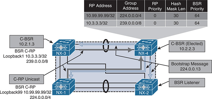
Figure 13-16 PIM BSR Topology
NX-1 is configured to be a C-RP for the 224.0.0.0/4 multicast group range (see Example 13-62). Because routers do not listen for or forward BSR messages by default, the device is configured with the ip pim bsr listen forward command. After NX-1 learns of the BSR address through a received bootstrap message, it begins sending unicast C-RP messages advertising the willingness to be an RP for 224.0.0.0/4.
The output of show ip pim rp provides the RP-to-group mapping selection being used, based on the information received from the bootstrap message originated by the elected BSR.
Example 13-62 BSR Configuration on NX-1
!Command: show running-config pim
feature pim
ip pim sparse-mode
interface loopback0
ip pim sparse-mode
interface loopback99
ip pim sparse-mode
interface Ethernet3/17
ip pim sparse-mode
interface Ethernet3/18
ip pim sparse-mode
NX-1# show ip pim rp
PIM RP Status Information for VRF "default"
BSR: 10.2.2.3, uptime: 06:36:03, expires: 00:02:00,
BSR RP Candidate policy: None
BSR RP policy: None
Auto-RP Announce policy: None
Auto-RP Discovery policy: None
The elected BSR is NX-4 because its BSR IP address is higher than that of NX-3 (10.2.2.3 vs. 10.2.1.3); both C-BSRs have equal default priority of 64. The ip pim bsr-candidate loopback0 command configures NX-4 to be a C-BSR and allows it to begin sending periodic bootstrap messages. The output of show ip pim rp confirms that the local device is the current BSR and provides a timer value that indicates when the next bootstrap message is sent. The hash length is the default value of 30, but it is configurable in the range of 0 to 32. Example 13-63 shows the configuration and RP mapping information for NX-4.
Example 13-63 BSR Configuration on NX-4
!Command: show running-config pim
feature pim
interface Vlan215
ip pim sparse-mode
interface Vlan216
ip pim sparse-mode
interface Vlan303
ip pim sparse-mode
interface loopback0
ip pim sparse-mode
interface Ethernet3/28
ip pim sparse-mode
interface Ethernet3/29
ip pim sparse-mode
NX-4# show ip pim rp
PIM RP Status Information for VRF "default"
BSR: 10.2.2.3*, next Bootstrap message in: 00:00:53,
BSR RP Candidate policy: None
BSR RP policy: None
Auto-RP Announce policy: None
Auto-RP Discovery policy: None
Example 13-64 shows the configuration of NX-3, which is configured to be both a C-RP for 239.0.0.0/8 and a C-BSR. NX-3 has a lower C-BSR address than NX-4, so it does not send any bootstrap messages after losing the BSR election.
Example 13-64 BSR Configuration on NX-3
interface Vlan215
ip pim sparse-mode
interface Vlan216
ip pim sparse-mode
interface Vlan303
ip pim sparse-mode
interface loopback0
ip pim sparse-mode
interface loopback1
ip pim sparse-mode
interface Ethernet3/28
ip pim sparse-mode
interface Ethernet3/29
ip pim sparse-mode
NX-3# show ip pim rp
PIM RP Status Information for VRF "default"
BSR: 10.2.2.3, uptime: 07:05:30, expires: 00:02:05,
BSR RP Candidate policy: None
BSR RP policy: None
Auto-RP Announce policy: None
Auto-RP Discovery policy: None
The final router to review is NX-2, which is acting only as a BSR listener and forwarder. In this configuration, NX-2 receives the bootstrap message from NX-4 and inspects its contents. It then selects the RP-to-group mapping for each group range and installs the entry in the local RP cache. Note that NX-4, NX-3, and NX-1 are BSR clients as well, but they are also acting as C-RPs or C-BSRs. Example 13-65 shows the configuration and RP mapping from NX-2.
Example 13-65 BSR Configuration on NX-2
feature pim
ip pim ssm range 232.0.0.0/8
interface Vlan115
ip pim sparse-mode
interface Vlan116
ip pim sparse-mode
interface Vlan1101
ip pim sparse-mode
interface Ethernet3/17
ip pim sparse-mode
interface Ethernet3/18
ip pim sparse-mode
NX-2# show ip pim rp
PIM RP Status Information for VRF "default"
BSR: 10.2.2.3, uptime: 07:11:35, expires: 00:01:39,
BSR RP Candidate policy: None
BSR RP policy: None
Auto-RP Announce policy: None
Auto-RP Discovery policy: None
Unlike Auto-RP, BSR messages are not constrained by a configured TTL scope. In a complex BSR design, defining which C-RPs are allowed to communicate with a particular BSR might be desirable. This is achieved by filtering the bootstrap messages and the RP-Candidate messages using the ip pim bsr [bsr-policy | rp-candidate-policy] commands and using a route map for filtering purposes.
Similar to Auto-RP, the show ip pim internal event-history rp command is used to monitor C-BSR, C-RP, and bootstrap message activity on a router. Example 13-66 gives a sample of this event-history.
Example 13-66 PIM Event-History for RP from NX-4 with BSR
rp events for PIM process
02:50:51.766388 pim [13449]::Group range 239.0.0.0/8 cached
02:50:51.766385 pim [13449]::(default) pim_add_rp: RP:10.3.3.3
rp_change:no change_flag: yes
bidir:no, group:239.0.0.0/8 rp_priority: 0, static: no, action: Permit,
prot_souce: 2 hash_len: 30
02:50:51.766325 pim [13449]::(default) pim_add_rp: Received rp_entry from
caller: RP: 10.3.3.3 bidir:no, group:239.0.0.0/8 rp_priority: 0, static:
no, prot_souce: 2 override: no hash_len: 30 holdtime: 150
02:50:51.766304 pim [13449]::RP 10.3.3.3, prefix count: 1, priority: 0,
holdtime: 150
02:50:51.766297 pim [13449]::Received Candidate-RP from 10.3.3.3, length: 76
02:50:09.705668 pim [13449]::Group range 224.0.0.0/4 cached
02:50:09.705664 pim [13449]::(default) pim_add_rp: RP:10.99.99.99 rp_change:no change_flag:
yes bidir:no, group:224.0.0.0/4 rp_priority: 0, static: no, action: Permit,
prot_souce: 2 hash_len: 30
02:50:09.705603 pim [13449]::(default) pim_add_rp: Received rp_entry from
caller: RP: 10.99.99.99 bidir:no, group:224.0.0.0/4 rp_priority: 0, static:
no, prot_souce: 2 override: no hash_len: 30 hold time: 150
02:50:09.705581 pim [13449]::RP 10.99.99.99, prefix count: 1, priority: 0,
holdtime: 150
02:50:09.705574 pim [13449]::Received Candidate-RP from 10.99.99.99, length: 76
02:50:03.996080 pim [13449]::Send Bootstrap message on Vlan216
02:50:03.996039 pim [13449]::Send Bootstrap message on Vlan215
02:50:03.995995 pim [13449]::Send Bootstrap message on Vlan303
02:50:03.995940 pim [13449]::Send Bootstrap message on Ethernet3/29
02:50:03.995894 pim [13449]::Send Bootstrap message on Ethernet3/28
02:50:03.995863 pim [13449]:: RP 10.3.3.3, priority: 0, holdtime 150
02:50:03.995860 pim [13449]::Group range 239.0.0.0/8, RPs:
02:50:03.995857 pim [13449]:: RP 10.99.99.99, priority: 0, holdtime 150
02:50:03.995853 pim [13449]::Group range 224.0.0.0/4, RPs:
02:50:03.995847 pim [13449]::Build Bootstrap message, priority: 64, hash-len: 30
In addition to the event-history output, the show ip pim statistics command is useful for viewing device-level aggregate counters for the various messages associated with BSR and for troubleshooting. Example 13-67 shows the output from NX-4.
Example 13-67 PIM Statistics on NX-4 with BSR
Register processing (sent/received):
Registers: 0/0, Null registers: 0/0, Register-Stops: 0/0
Registers received and not RP: 0
Registers received for SSM/Bidir groups: 0/0
Auto-RP Announces: 0/0, Auto-RP Discoveries: 0/0
Auto-RP RPF failed: 0, Auto-RP from border interfaces: 0
Auto-RP invalid type: 0, Auto-RP TTL expired: 0
Auto-RP received but not listen configured: 0
General errors:
Control-plane RPF failure due to no route found: 9
Data-plane RPF failure due to no route found: 0
Data-plane no multicast state found: 0
Data-plane create route state count: 10
vPC packet stats:
rpf-source metric requests sent: 11
rpf-source metric requests received: 483
rpf-source metric request send error: 0
rpf-source metric response sent: 483
rpf-source metric response received: 11
rpf-source metric response send error: 0
rpf-source metric rpf change trigger sent: 2
rpf-source metric rpf change trigger received: 13
rpf-source metric rpf change trigger send error: 0
When multiple C-RPs exist for a particular group range, determining which group range is mapped to which RP can be challenging. NX-OS provides two commands to assist the user (see Example 13-68).
The first command is the show ip pim group-range [group address] command, which provides the current PIM mode used for the group, the RP address, and the method used to obtain the RP address. The second command is the show ip pim rp-hash [group address] command, which runs the PIM hash function on demand and provides the hash result and selected RP among all the C-RPs for the group range.
Example 13-68 PIM Group–to–RP Mapping Information from NX-2
PIM Group-Range Configuration for VRF "default"
Group-range Action Mode RP-address Shrd-tree-range Origin
PIM Hash Information for VRF "default"
PIM RPs for group 239.1.1.1, using hash-length: 30 from BSR: 10.2.2.3
RP 10.99.99.99, hash: 645916811
Running both Auto-RP and BSR in the same PIM domain is not supported. Auto-RP and BSR both are capable of providing dynamic and redundant RP mapping to the network. If third-party vendor devices are also participating in the PIM domain, BSR is the IETF standard choice and allows for multivendor interoperability.
Anycast-RP Configuration and Verification
Redundancy is always a factor in modern network design. In a multicast network, no single device is more important to the network overall than the PIM RP. The previous section discussed Auto-RP and BSR, which provide redundancy in exchange for additional complexity in the election processes and the distribution of multicast group–to–RP mapping information in the network.
Fortunately, another approach is available for administrators who favor the simplicity of a static PIM RP but also desire RP redundancy. Anycast RP configuration involves multiple PIM routers sharing a single common IP address. The IP address is configured on a Loopback interface using a /32 mask. Each router that is configured with the anycast address advertises the connected host address into the network’s chosen routing protocol. Each router in the PIM domain is configured to use the anycast address as the RP. When an FHR needs to register a source, the network’s unicast routing protocol automatically routes the PIM message to the closest device configured with the anycast address. This allows many devices to share the load of PIM register messages and provides redundancy in the case of an RP failure.
Obviously, intentionally configuring the same IP address on multiple devices should be done with care. For example, any routing protocol or management functions that could mistakenly use the anycast Loopback address as a router-id or source address should be configured to always use a different interface. With those caveats addressed, using an anycast address is perfectly safe, and this is a popular option in large and multiregional multicast networks.
Two methods are available for configuring anycast RP functionality:
Anycast RP with Multicast Source Discovery Protocol (MSDP)
PIM Anycast RP as specified in RFC 4610
This section examines both options.
Anycast RP with MSDP
The MSDP protocol defines a way for PIM RPs to advertise the knowledge of registered, active sources to each other. Initially, MSDP was designed to connect multiple independent PIM domains that each use their own PIM RP together. However, the protocol was also chosen as an integral part of the Anycast RP specification in RFC 3446.
MSDP allows each PIM RP configured with the Anycast RP address to act independently, while still sharing active source information with all other Anycast RPs in the domain. For example, in the topology in Figure 13-17, an FHR can register a source for a multicast group with Anycast RP NX-3, and then a receiver can join that group through Anycast RP NX-4. After traffic is received through the RPT, normal PIM SPT switchover behavior occurs on the LHR.
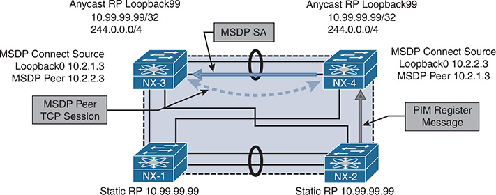
Figure 13-17 Anycast RP with MSDP
Anycast RP with MSDP requires that each Anycast RP have an MSDP peer with every other Anycast RP. The MSDP peer session is established over Transmission Control Protocol (TCP) port 639. When the TCP session is established, MSDP can send keepalive and source-active (SA) messages between peers, encoded in a TLV format.
When an Anycast RP learns of a new source, it uses the SA message to inform all its MSDP peers about that source. The SA message contains the following information:
Unicast address of the multicast source
Multicast group address
IP address of the PIM RP (originator-id)
When the peer receives the MSDP SA, it subjects the message to an RPF check, which compares the IP address of the PIM RP in the SA message to the MSDP peer address. This address must be a unique IP address on each MSDP peer and cannot be an anycast address. NX-OS provides the ip msdp originator-id [address] command to configure the originating RP address that gets used in the SA message.
Note
Other considerations for the MSDP SA message RPF check are not relevant to the MSDP example used in this chapter. Section 10 of RFC 3618 gives the full explanation of the MSDP SA message RPF check.
If the SA message is accepted, it is sent to all other MSDP peers except the one from which the SA message was received. A concept called a mesh group can be configured to reduce the SA message flooding when many anycast RPs are configured with MSDP peering. The mesh group is a group of MSDP peers that have an MSDP neighbor with every other mesh group peer. Therefore, any SA message received from a mesh group peer does not need to be forwarded to any peers in the mesh group because all peers should have received the same message from the originator.
MSDP supports the use of SA filters, which can be used to enforce specific design parameters through message filtering. SA filters are configured with the ip msdp sa-policy [peer address] [route-map | prefix-list] command. It is also possible to limit the total number of SA messages from a peer with the ip msdp sa-limit [peer address] [number of SAs] command.
The example network in Figure 13-17 was configured with anycast RPs and MSDP between NX-3 and NX-4. NX-3 and NX-4 are both configured with the Anycast RP address of 10.99.99.99 on their Loopback99 interfaces. The Loopback0 interface on NX-3 and NX-4 is used to establish the MSDP peering. NX-1 and NX-2 are statically configured to use the anycast RP address of 10.99.99.99.
The output of Example 13-69 shows the configuration for anycast RP with MSDP from NX-3. As with PIM, before MSDP can be configured, the feature must be enabled with the feature msdp command. The originator-id and the MSDP connect source are both using the unique IP address configured on interface Loopback0, while the PIM RP is configured to use the anycast IP address of Loopback99. The MSDP peer address is the Loopback0 interface of NX-4.
Example 13-69 NX-3 Anycast RP with MSDP Configuration
!Command: show running-config pim
feature pim
interface Vlan215
ip pim sparse-mode
interface Vlan216
ip pim sparse-mode
interface Vlan303
ip pim sparse-mode
interface loopback0
ip pim sparse-mode
interface loopback99
ip pim sparse-mode
interface Ethernet3/28
ip pim sparse-mode
interface Ethernet3/29
ip pim sparse-mode
NX-3# show run msdp
feature msdp
show running-config interface lo0
interface loopback0
ip address 10.2.1.3/32
ip router ospf 1 area 0.0.0.0
ip pim sparse-mode
!Command: show running-config interface loopback99
interface loopback99
ip address 10.99.99.99/32
ip router ospf 1 area 0.0.0.0
ip pim sparse-mode
The configuration of NX-4 is similar to that of NX-3; the only difference is the Loopback0 IP address and the IP address of the MSDP peer, which is NX-3’s Loopback0 address. Example 13-70 contains the anycast RP with MSDP configuration for NX-4.
Example 13-70 NX-4 Anycast RP with MSDP Configuration
!Command: show running-config pim
feature pim
interface Vlan215
ip pim sparse-mode
interface Vlan216
ip pim sparse-mode
interface Vlan303
ip pim sparse-mode
interface loopback0
ip pim sparse-mode
interface loopback99
ip pim sparse-mode
interface Ethernet3/28
ip pim sparse-mode
interface Ethernet3/29
ip pim sparse-mode
NX-3# show run msdp
feature msdp
show running-config interface lo0
interface loopback0
ip address 10.2.2.3/32
ip router ospf 1 area 0.0.0.0
ip pim sparse-mode
!Command: show running-config interface loopback99
interface loopback99
ip address 10.99.99.99/32
ip router ospf 1 area 0.0.0.0
ip pim sparse-mode
After the configuration is applied, NX-3 and NX-4 establish the MSDP peering session between their Loopback0 interfaces using TCP port 639. The MSDP peering status can be confirmed with the show ip msdp peer command (see Example 13-71). The output provides an overview of the MSDP peer status and how long the peer has been established. It also lists any configured SA policy filters or limits and provides counters for the number of MSDP messages exchanged with the peer.
Example 13-71 MSDP Peer Status on NX-4
MSDP peer 10.2.1.3 for VRF "default"
AS 0, local address: 10.2.2.3 (loopback0)
Description: none
Connection status: Established
Uptime(Downtime): 00:13:34
Password: not set
Keepalive Interval: 60 sec
Keepalive Timeout: 90 sec
Reconnection Interval: 10 sec
Policies:
SA in: none, SA out: none
SA limit: unlimited
Member of mesh-group: no
Statistics (in/out):
Last messaged received: 00:00:55
Remote/Local Port 65205/639
RPF check failures: 0
Cache Lifetime: 00:03:30
Established Transitions: 1
Connection Attempts: 0
Discontinuity Time: 00:13:34
As in previous examples in this chapter, multicast source 10.115.1.4 is attached to NX-2 on its VLAN 115 interface. When 10.115.1.4 starts sending traffic for group 239.115.115.1, NX-2 sends a PIM register message to its RP address of 10.99.99.99. Both NX-3 and NX-4 own this address because it is the anycast address. In this example, NX-2 sends the register message to NX-4. When the register message arrives, NX-4 replies with a register-stop and creates an (S, G) mroute entry. NX-4 also creates an MSDP SA message that is sent to NX-3 with the source IP address, group, and configured originator-id in the RP field. NX-3 receives the message and evaluates it for the RPF check and any filters that are applied. If all checks pass, the entry is added to the SA cache and an MSDP created mroute (S, G) state is added to the SA cache and an MSDP created mroute (S, G) state is added to the mroute table (see Example 13-72).
Example 13-72 MSDP SA State and MROUTE Status on NX-3
SA State per ASN, VRF "default" - 1 total entries
note: only asn below 65536
<asn>: <(S,G) count>/<group count>
0: 1/1
NX-3# show ip msdp sa-cache
MSDP SA Route Cache for VRF "default" - 1 entries
Source Group RP ASN Uptime
10.115.1.4 239.115.115.1 10.2.2.3 0 01:21:30
NX-3# show ip mroute
IP Multicast Routing Table for VRF "default"
(*, 239.115.115.1/32), uptime: 16:41:50, igmp ip pim
Incoming interface: loopback99, RPF nbr: 10.99.99.99
Outgoing interface list: (count: 1)
Vlan215, uptime: 16:41:50, igmp
(10.115.1.4/32, 239.115.115.1/32), uptime: 01:23:25, ip mrib msdp pim
Incoming interface: Ethernet3/28, RPF nbr: 10.1.23.2
Outgoing interface list: (count: 1)
The most common anycast RP problems relate to missing state or no synchronization between the configured RPs for active sources. The first step in troubleshooting this type of problem is to identify which of the possibly many anycast RPs are being sent the register message from the FHR for the problematic source and group. Next, ensure that the MSDP peer session is established between all anycast RPs. If the (S, G) mroute entry exists on the originating RP, the problem could result from MSDP not advertising the source and group through an SA message. The NX-OS event-history logs or the Ethanalyzer can help determine which messages are being sent from one MSDP peer to the next.
When 10.115.1.4 starts sending traffic to 239.115.115.1, NX-2 sends a PIM register message to NX-4. When the source is registered, the output in Example 13-73 is stored in the show ip msdp internal event-history route and show ip msdp internal event-history tcp commands. This event-history has the following interesting elements:
SA messages were added to the SA Buffer at 04:06:14 and 04:13:27.
The MSDP TCP event-history can be correlated to those time stamps.
The 104-byte message was an encapsulated data packet SA message.
The 20-byte message was a null register data packet SA message.
The 3-byte messages are keepalives to and from the peer.
Example 13-73 MSDP Event-History on NX-4
routes events for MSDP process
2017 Nov 1 04:12:47.967291 msdp [1621]: : Processing for (10.115.1.4/32, 239.115.115.1/32)
2017 Nov 1 04:12:47.967286 msdp [1621]: : Processing for (*, 239.115.115.1/32)
NX-4# show ip msdp internal event-history tcp
tcp events for MSDP process
04:13:27.816367 msdp [1621]: : TCP at peer 10.2.1.3 accepted 20 bytes,
0 bytes left to send from buffer, total send bytes: 0
04:13:27.815998 msdp [1621]: : 20 bytes enqueued for send (20 bytes in buffer)
to peer 10.2.1.3
04:06:04.659887 msdp [1621]: : TCP at peer 10.2.1.3 accepted 104 bytes, 0 bytes
left to send from buffer, total send bytes: 0
04:06:04.659484 msdp [1621]: : 104 bytes enqueued for send (104 bytes in buffer)
to peer 10.2.1.3
04:05:17.778269 msdp [1621]: : Read 3 bytes from TCP with peer 10.2.1.3 ,
buffer offset 0
04:05:17.736188 msdp [1621]: : TCP at peer 10.2.1.3 accepted 3 bytes, 0 bytes
left to send from buffer, total send bytes: 0
04:04:20.111337 msdp [1621]: : Connection established on passive side
04:04:13.085442 msdp [1621]: : We are listen (passive) side of connection, using
local address 10.2.2.3
Even if the MSDP SA message is correctly generated and advertised to the peer, it can still be discarded because of an RPF failure, an SA failure, or an SA limit. The same event-history output on the peer is used to determine why MSDP is discarding the message upon receipt. Remember that the PIM RP is the root of the RPT. If an LHR has an (S, G) state for a problematic source and group, the problem is likely to be on the SPT rooted at the source.
All examples in the “Anycast RP with MSDP” section of this chapter used a static PIM RP configuration. Using the anycast RP with MSDP functionality in combination with Auto-RP or BSR is fully supported, for dynamic group-to-RP mapping and provides the additional benefits of an anycast RP.
PIM Anycast RP
RFC 4610 specifies PIM anycast RP. The design goal of PIM anycast RP is to remove the dependency on MSDP and to achieve anycast RP functionality using only the PIM protocol. The benefit of this approach is that the end-to-end process has one fewer control plane protocol and one less point of failure or misconfiguration.
PIM anycast RP relies on the PIM register and register-stop messages between the anycast RPs to achieve the same functionality that MSDP provided previously. PIM anycast is designed around the following requirements:
Each anycast RP is configured with the same anycast RP address.
Each anycast RP also has a unique address to use for PIM messages between the anycast RPs.
Every anycast RP is configured with the addresses of all the other anycast RPs.
The example network in Figure 13-18 helps in understanding PIM anycast RP configuration and troubleshooting.
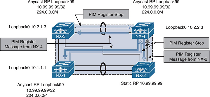
Figure 13-18 PIM Anycast RP
As with the previous examples in this chapter, a multicast source 10.115.1.4 is attached to NX-2 on VLAN 115 and begins sending to group 239.115.115.4. This is not illustrated in Figure 13-18, for clarity. NX-2 is the FHR and is responsible for registering the source with the RP. When NX-2 builds the register message, it performs a lookup in the unicast routing table to find the anycast RP address 10.99.99.99. The anycast address 10.99.99.99 is configured on NX-1, NX-3, and NX-4, which are all members of the same anycast RP set. The register message is sent to NX-4 following the best routing in the routing table.
When the register message arrives at NX-4, the PIM anycast RP functionality implements additional checks and processing on the received message. NX-4 builds its (S, G) state just as any PIM RP would. However, NX-4 looks at the source of the register message and determines that because the address is not part of the anycast RP set, it must be an FHR. NX-4 must then build a register message originated from its own Loopback0 address and send it to all other anycast RPs that are in the configured anycast RP set. NX-4 then sends a register-stop message to the FHR, NX-2. When NX-1 and NX-3 receive the register message from NX-4, they also build an (S, G) state in the mroute table and reply back to NX-4 with a register stop. Because NX-4 is part of the anycast RP set on NX-1 and NX-3, they recognize NX-4 as a member of the anycast RP set and no additional register messages are required to be built on NX-1 and NX-3.
The PIM anycast RP configuration uses the standard PIM messaging of register and register-stop that happens between FHRs and RPs and applies it to the members of the anycast RP set. The action of building a register message to inform the other anycast RPs is based on the source address of the register. If it is not a member of the anycast RP set, then the sender of the message must an FHR, so a register message is sent to the other members of the anycast RP set. The approach is elegant and straightforward.
Example 13-74 shows the configuration for NX-4. The static RP of 10.99.99.99 for groups 224.0.0.0/4 is configured on every PIM router in the domain. The anycast RP set is exactly the same on NX-1, NX-3, and NX-4 and includes all anycast RP Loopback0 interface addresses, including the local device’s own IP.
Example 13-74 PIM Anycast RP Configuration on NX-4
!Command: show running-config pim
feature pim
interface Vlan215
ip pim sparse-mode
interface Vlan216
ip pim sparse-mode
interface Vlan303
ip pim sparse-mode
interface loopback0
ip pim sparse-mode
interface loopback99
ip pim sparse-mode
interface Ethernet3/28
ip pim sparse-mode
interface Ethernet3/29
ip pim sparse-mode
The same debugging methodology used for the PIM source registration process can be applied to the PIM Anycast RP set. The show ip pim internal event-history null-register and show ip pim internal event-history data-header-register outputs provide a record of the messages being exchanged between the Anycast-RP set and any FHRs that are sending register messages to the device.
Example 13-75 shows the event-history output from NX-4. The null register message from 10.115.1.254 is from NX-2, which is the FHR. After adding the mroute entry, NX-4 forwards the register message to the other members of the anycast RP set and then receives a register stop message in response.
Example 13-75 PIM Null Register Event-History on NX-4
04:26:04.289082 pim [31641]:: Received Register-Stop from 10.2.1.3 for
(10.115.1.4/32, 239.115.115.1/32)
04:26:02.289082 pim [31641]:: Received Register-Stop from 10.1.1.1 for
(10.115.1.4/32, 239.115.115.1/32)
04:25:02.126926 pim [31641]:: Send Register-Stop to 10.115.1.254 for
(10.115.1.4/32, 239.115.115.1/32)
04:25:02.126909 pim [31641]:: Forward Register to Anycast-RP member 10.2.1.3
04:25:02.126885 pim [31641]:: Forward Register to Anycast-RP member 10.1.1.1
04:25:02.126874 pim [31641]:: RP 10.99.99.99 is an Anycast-RP
04:25:02.126866 pim [31641]:: Add new route (10.115.1.4/32, 239.115.115.1/32)
to MRIB, multi-route TRUE
04:25:02.126715 pim [31641]:: Create route for (10.115.1.4/32, 239.115.115.1/32)
04:25:02.126600 pim [31641]:: Received NULL Register from 10.115.1.254 for (10.115.1.4/32, 239.115.115.1/32) (pktlen 20)
All examples in the PIM anycast RP section of this book used a static PIM RP configuration. Using the PIM anycast RP functionality in combination with Auto-RP or BSR is fully supported, for dynamic group-to-RP mapping and to benefit from the advantages of anycast RP.
PIM Source Specific Multicast
The PIM SSM service model, defined in RFC 4607, allows a receiver to be joined directly to the source tree without the need for a PIM RP. This type of multicast delivery is optimized for one-to-many communication and is used extensively for streaming video applications such as IPTV. SSM is also popular for the provider multicast groups used to deliver IP Multicast over L3 VPN (MVPN).
SSM functions without a PIM RP because the receiver has knowledge of each source and group address that it will join. This knowledge can be preconfigured in the application, resolved through a Domain Name System (DNS) query, or mapped at the LHR. Because no PIM RP exists in SSM, the entire concept of the RPT or shared tree is eliminated along with the SPT switchover. The process of registering a source with the RP is also no longer required, which results in greater efficiency and less protocol overhead, compared to PIM ASM.
PIM SSM refers to a (source, group) combination as a uniquely identifiable channel. In PIM ASM mode, any source may send traffic to a group. In addition, the receiver implicitly joins any source that is sending traffic to the group address. In SSM, the receiver requests each source explicitly through an IGMPv3 membership report. This allows different applications to share the same multicast group address by using a unique source address. Because NX-OS implements an IP-based IGMP snooping table by default, it is possible for hosts to receive traffic for only the sources requested. A MAC-based IGMP snooping table has no way to distinguish different source addresses sending traffic to the same group.
Note
SSM can natively join a source in another PIM domain because the source address is known to the receiver. PIM ASM and BiDIR require the use of additional protocols and configuration to enable interdomain multicast to function.
The topology in Figure 13-19 applies to the discussion on the configuration and verification of PIM SSM.
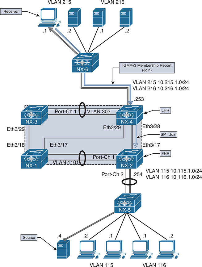
Figure 13-19 PIM SSM Topology
When a receiver in VLAN 215 joins (10.115.1.4, 232.115.115.1), it generates an IGMPv3 membership report. This join message includes the group and source address for the channel the receiver is interested in. The LHR (NX-4) builds an (S, G) mroute entry after it receives this join message and looks up the RPF interface toward the source. An SPT PIM join is sent to NX-2, which will also create an (S, G) state.
The (S, G) on NX-2 is created by either receiving the PIM join from NX-4 or receiving data traffic from the source, depending on which event occurs first. If no receiver exists for an SSM group, the FHR silently discards the traffic and the OIL of the mroute becomes empty. When the (S, G) SPT state is built, traffic flows downstream from the source 10.115.1.4 directly to the receiver on the SSM group 232.115.115.1.
SSM Configuration
The configuration for PIM SSM requires ip pim sparse-mode to be configured on each interface participating in multicast forwarding. There is no PIM RP to be defined, but any interface connected to a receiver must be configured with ip igmp version 3. The ip pim ssm-range command is configured by default to the IANA reserved range of 232.0.0.0/8. Configuring a different range of addresses is supported, but care must be taken to ensure that this is consistent throughout the PIM domain. Otherwise, forwarding is broken because the misconfigured router assumes that this is an ASM group and it does not have a valid PIM RP-to-group mapping.
The ip igmp ssm-translate [group] [source] command is used to translate an IGMPv1 or IGMPv2 membership report that does not contain a source address to an IGMPv3-compatible state entry. This is not required if all hosts attached to the interface support IGMPv3.
Example 13-76 shows the output of the complete SSM configuration for NX-2.
Example 13-76 PIM SSM Configuration on NX-2
!Command: show running-config pim
feature pim
interface Vlan115
ip pim sparse-mode
interface Vlan116
ip pim sparse-mode
interface Vlan1101
ip pim sparse-mode
interface Ethernet3/17
ip pim sparse-mode
interface Ethernet3/18
ip pim sparse-mode
!Command: show running-config interface Vlan115
interface Vlan115
no shutdown
no ip redirects
ip address 10.115.1.254/24
ip ospf passive-interface
ip router ospf 1 area 0.0.0.0
ip pim sparse-mode
The configuration for NX-4 is similar to NX-2 (see Example 13-77).
Example 13-77 PIM SSM Configuration on NX-4
!Command: show running-config pim
feature pim
interface Vlan215
ip pim sparse-mode
interface Vlan216
ip pim sparse-mode
interface Vlan303
ip pim sparse-mode
interface loopback0
ip pim sparse-mode
interface Ethernet3/28
ip pim sparse-mode
interface Ethernet3/29
ip pim sparse-mode
NX-4# show run interface vlan215
!Command: show running-config interface Vlan215
interface Vlan215
no shutdown
no ip redirects
ip address 10.215.1.253/24
ip ospf passive-interface
ip router ospf 1 area 0.0.0.0
ip pim sparse-mode
NX-1 and NX-3 are configured in a similar way. Because they do not play a role in forwarding traffic in this example, the configuration is not shown.
SSM Verification
To verify the SPT used in SSM, it is best to begin at the LHR where the receiver is attached. If the receiver sent an IGMPv3 membership report, an (S, G) state is present on the LHR. If this entry is missing, check the host for the proper configuration. SSM requires that the host have knowledge of the source address, and it works correctly only when the host knows which source to join, or when a correct translation is configured when the receiver is not using IGMPv3.
If any doubt arises that the host is sending a correct membership report, perform an Ethanalyzer capture on the LHR. In addition, the output of show ip igmp groups and show ip igmp snooping groups can be used to confirm that the interface has received a valid membership report. Example 13-78 shows this output from NX-4. Because this is IGMPv3 and NX-OS uses an IP-based table, both the source and group information is present.
Example 13-78 IGMPv3 Verification on NX-4
IGMP Connected Group Membership for VRF "default" - 1 total entries
Type: S - Static, D - Dynamic, L - Local, T - SSM Translated
Group Address Type Interface Uptime Expires Last Reporter
232.115.115.1
10.115.1.4 D Vlan215 01:26:41 00:02:06 10.215.1.1 NX-4# show ip igmp snooping groups
Type: S - Static, D - Dynamic, R - Router port, F - Fabricpath core port
Vlan Group Address Ver Type Port list
215 */* - R Vlan215 Po2
303 */* - R Vlan303 Po1
When NX-4 receives the membership report, an (S, G) mroute entry is created. The (S, G) mroute state is created because the receiver is already aware of the precise source address it wants to join for the group. In contrast, PIM ASM builds a (*, G) state because the LHR does not yet know the source. Example 13-79 shows the mroute table for NX-4.
Example 13-79 PIM SSM MROUTE Entry on NX-4
IP Multicast Routing Table for VRF "default"
(*, 232.0.0.0/8), uptime: 00:02:07, pim ip
Incoming interface: Null, RPF nbr: 0.0.0.0
Outgoing interface list: (count: 0)
(10.115.1.4/32, 232.115.115.1/32), uptime: 00:00:33, igmp ip pim
Incoming interface: Ethernet3/28, RPF nbr: 10.2.23.2
Outgoing interface list: (count: 1)
The RPF interface to 10.115.1.4 is Ethernet 3/28, which connects directly to NX-2. The show ip pim internal event-history join-prune command can be checked to confirm that the SPT join has been sent from NX-4. Example 13-80 shows the output of this command.
Example 13-80 PIM SSM Event-History Join-Prune on NX-4
03:44:55.372584 pim [10572]:: Send Join-Prune on Ethernet3/28, length: 34
03:44:55.372553 pim [10572]:: Put (10.115.1.4/32, 239.115.115.1/32),
S in join-list for nbr 10.2.23.2
03:44:55.372548 pim [10572]:: wc_bit = FALSE, rp_bit = FALSE
The PIM Join is received on NX-2, and the OIL of the mroute entry is updated to include Ethernet 3/17, which is directly connected with NX-4. Example 13-81 gives the event-history for PIM join-prune and the mroute entry from NX-2.
Example 13-81 PIM SSM Event-History Join-Prune on NX-2
join-prune events for PIM process
03:44:55.429867 pim [7192]: : (10.115.1.4/32, 232.115.115.1/32) route exists
, RPF if Vlan115, to us
03:44:13.429837 pim [7192]: : pim_receive_join: We are target comparing with iod
03:44:13.429794 pim [7192]: : pim_receive_join: route:
(10.115.1.4/32, 232.115.115.1/32), wc_bit: FALSE, rp_bit: FALSE
03:44:13.429780 pim [7192]: : Received Join-Prune from 10.2.23.3 on Ethernet3/17
, length: 34, MTU: 9216, ht: 210
NX-2# show ip mroute
IP Multicast Routing Table for VRF "default"
(*, 232.0.0.0/8), uptime: 00:00:47, pim ip
Incoming interface: Null, RPF nbr: 0.0.0.0
Outgoing interface list: (count: 0)
(10.115.1.4/32, 232.115.115.1/32), uptime: 00:00:46, ip pim
Incoming interface: Vlan115, RPF nbr: 10.115.1.4
Troubleshooting SSM is more straightforward than troubleshooting PIM ASM or BiDIR. No PIM RP is required, which eliminates configuration errors and protocol complexity associated with dynamic RP configuration, anycast RP, and incorrect group-to-RP mapping. Additionally, there is no source registration process, RPT, or SPT switchover, which further simplifies troubleshooting.
Most problems with SSM result from a misconfigured SSM group range on a subset of devices or stem from a receiver host that is misconfigured or that is attempting to join the wrong source address. The troubleshooting methodology is similar to the one to address problems with the SPT in PIM ASM: Start at the receiver and work through the network hop by hop until the FHR connected to the source is reached. Packet capture tools such as ELAM, ACLs, or SPAN can be used to isolate any packet forwarding problems on a router along the tree.
Multicast and Virtual Port-Channel
A port-channel is a logical bundle of multiple physical member link interfaces. This configuration allows multiple physical interfaces to behave as a single interface to upper-layer protocols. Virtual port-channels (vPC) are a special type of port-channel that allow a pair of peer switches to connect to another device and appear as a single switch.
This architecture provides loop-free redundancy at L2 by synchronizing forwarding state and L2 control plane information between the vPC peers. Strict forwarding rules are implemented for traffic that is to be sent on a vPC interface, to avoid loops and duplicated packets.
Although L2 state is synchronized between the vPC peers through Cisco Fabric Services (CFS), both peers have an independent L3 control plane. As with standard port-channels, a hash table is used to determine which member link is chosen to forward packets of a particular flow. Traffic arriving from a vPC-connected host is received on either vPC peer, depending on the hash result. Because of this, both peers must be capable of forwarding traffic to or from a vPC-connected host. NX-OS supports both multicast sources and receivers connected behind vPC. Support for multicast traffic over vPC requires the following:
IGMP is synchronized between peers with the CFS protocol. This populates the IGMP snooping forwarding tables on both vPC peers with the same information. PIM and mroutes are not synchronized with CFS.
The vPC peer link is an mrouter port in the IGMP snooping table, which means that all multicast packets received on a vPC VLAN are forwarded across the peer link to the vPC peer.
Packets received from a vPC member port and sent across the peer link are not sent out of any vPC member port on the receiving vPC peer.
With vPC-connected multicast sources, both vPC peers can forward multicast traffic to an L3 OIF.
With vPC-connected receivers, the vPC peer with the best unicast metric to the source will forward packets. If the metrics are the same, the vPC operational primary forwards the packets. This vPC assert mechanism is implemented through CFS.
PIM SSM and PIM BiDIR are not supported with vPC because of the possibility of incorrect forwarding behavior.
Note
Although multicast source and receiver traffic is supported over vPC, an L3 PIM neighbor from the vPC peers to a vPC-connected multicast router is not yet supported.
vPC-Connected Source
The example network topology in Figure 13-20 illustrates the configuration and verification of a vPC-connected multicast source.
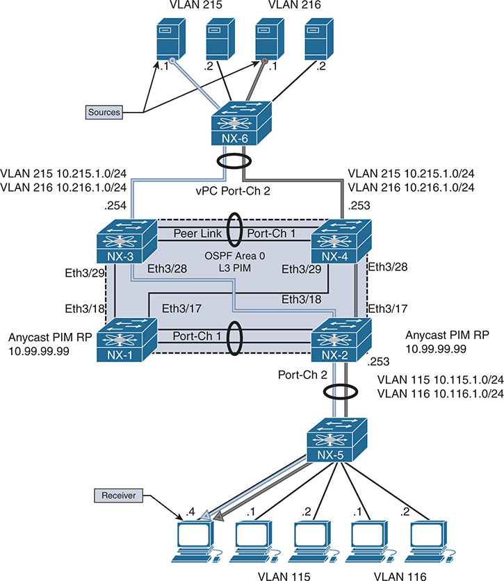
Figure 13-20 vPC-Connected Source Topology
In Figure 13-20, the multicast sources are 10.215.1.1 in VLAN 215 and 10.216.1.1 in VLAN 216 for group 239.215.215.1. Both sources are attached to L2 switch NX-6, which uses its local hash algorithm to choose a member link to forward the traffic to. NX-3 and NX-4 are vPC peers and act as FHRs for VLAN 215 and VLAN 216, which are trunked across the vPC with NX-6.
The receiver is attached to VLAN 115 on NX-2, which is acting as the LHR. The network was configured with a static PIM anycast RP of 10.99.99.99, which is Loopback 99 on NX-1 and NX-2.
When vPC is configured, no special configuration commands are required for vPC and multicast to work together. Multicast forwarding is integrated into the operation of vPC by default and is enabled automatically. CFS handles IGMP synchronization, and PIM does not require the user to enable any vPC-specific configuration beyond enabling ip pim sparse-mode on the vPC VLAN interfaces.
Example 13-82 shows the PIM and vPC configuration for NX-4.
Example 13-82 Multicast vPC Configuration on NX-4
!Command: show running-config pim
feature pim
interface Vlan215
ip pim sparse-mode
interface Vlan216
ip pim sparse-mode
interface Vlan303
ip pim sparse-mode
interface loopback0
ip pim sparse-mode
interface Ethernet3/28
ip pim sparse-mode
interface Ethernet3/29
ip pim sparse-mode
NX-4# show run vpc
!Command: show running-config vpc
feature vpc
vpc domain 2
peer-switch
peer-keepalive destination 10.33.33.1 source 10.33.33.2 vrf peerKA
peer-gateway
interface port-channel1
vpc peer-link
interface port-channel2
vpc 2
Example 13-83 shows the PIM and vPC configuration on the vPC peer NX-3.
Example 13-83 Multicast vPC Configuration on NX-3
!Command: show running-config pim
feature pim
interface Vlan215
ip pim sparse-mode
interface Vlan216
ip pim sparse-mode
interface Vlan303
ip pim sparse-mode
interface loopback0
ip pim sparse-mode
interface Ethernet3/28
ip pim sparse-mode
interface Ethernet3/29
ip pim sparse-mode
NX-4# show run vpc
!Command: show running-config vpc
feature vpc
vpc domain 2
peer-switch
peer-keepalive destination 10.33.33.1 source 10.33.33.2 vrf peerKA
peer-gateway
interface port-channel1
vpc peer-link
interface port-channel2
vpc 2
After implementing the configuration, the next step is to verify that PIM and IGMP are operational on the vPC peers. The output of show ip pim interface from NX-4 indicates that VLAN 215 is a vPC VLAN (see Example 13-84). Note that NX-3 (10.215.1.254) is the PIM DR and handles registration of the source with the PIM RP. PIM neighbor verification on NX-3 and NX-4 for the non-vPC interfaces and for NX-1 and NX-2 is identical to the previous examples shown in the PIM ASM section of this chapter.
Example 13-84 Multicast vPC PIM Interface on NX-4
! Output omitted for brevity
PIM Interface Status for VRF “default”
Vlan215, Interface status: protocol-up/link-up/admin-up
IP address: 10.215.1.253, IP subnet: 10.215.1.0/24
PIM DR: 10.215.1.254, DR’s priority: 1
PIM neighbor count: 2
PIM hello interval: 30 secs, next hello sent in: 00:00:12
PIM neighbor holdtime: 105 secs
PIM configured DR priority: 1
PIM configured DR delay: 3 secs
PIM border interface: no
PIM GenID sent in Hellos: 0x29002074
PIM Hello MD5-AH Authentication: disabled
PIM Neighbor policy: none configured
PIM Join-Prune inbound policy: none configured
PIM Join-Prune outbound policy: none configured
PIM Join-Prune interval: 1 minutes
PIM Join-Prune next sending: 0 minutes
PIM BFD enabled: no
PIM passive interface: no
PIM VPC SVI: yes
PIM Auto Enabled: no
PIM vPC-peer neighbor: 10.215.1.254
PIM Interface Statistics, last reset: never
General (sent/received):
Hellos: 14849/4299 (early: 0), JPs: 0/13, Asserts: 0/0
Grafts: 0/0, Graft-Acks: 0/0
DF-Offers: 1/3, DF-Winners: 2/13, DF-Backoffs: 0/0, DF-Passes: 0/0
Errors:
Checksum errors: 0, Invalid packet types/DF subtypes: 0/0
Authentication failed: 0
Packet length errors: 0, Bad version packets: 0, Packets from self: 0
Packets from non-neighbors: 0
Packets received on passiveinterface: 0
JPs received on RPF-interface: 13
(*,G) Joins received with no/wrong RP: 0/0
(*,G)/(S,G) JPs received for SSM/Bidir groups: 0/0
JPs filtered by inbound policy: 0
JPs filtered by outbound policy: 0
The show ip igmp interface command in Example 13-85 indicates that VLAN 215 is a vPC VLAN. The output also identifies the PIM DR as the vPC peer, not the local interface.
Example 13-85 Multicast vPC IGMP Interface on NX-4
Vlan215, Interface status: protocol-up/link-up/admin-up
IP address: 10.215.1.253, IP subnet: 10.215.1.0/24
Active querier: 10.215.1.1, expires: 00:04:10, querier version: 2
Membership count: 0
Old Membership count 0
IGMP version: 2, host version: 2
IGMP query interval: 125 secs, configured value: 125 secs
IGMP max response time: 10 secs, configured value: 10 secs
IGMP startup query interval: 31 secs, configured value: 31 secs
IGMP startup query count: 2
IGMP last member mrt: 1 secs
IGMP last member query count: 2
IGMP group timeout: 260 secs, configured value: 260 secs
IGMP querier timeout: 255 secs, configured value: 255 secs
IGMP unsolicited report interval: 10 secs
IGMP robustness variable: 2, configured value: 2
IGMP reporting for link-local groups: disabled
IGMP interface enable refcount: 1
IGMP interface immediate leave: disabled
IGMP VRF name default (id 1)
IGMP Report Policy: None
IGMP State Limit: None
IGMP interface statistics: (only non-zero values displayed)
General (sent/received):
v2-queries: 2867/2908, v2-reports: 0/2898, v2-leaves: 0/31
v3-queries: 15/1397, v3-reports: 0/1393
Errors:
Packets with Local IP as source: 0, Source subnet check failures: 0
Query from non-querier:1
Report version mismatch: 4, Query version mismatch: 0
Unknown IGMP message type: 0
Interface PIM DR: vPC Peer
Interface vPC SVI: Yes
Interface vPC CFS statistics:
DR queries rcvd: 1
DR updates rcvd: 4
Identifying which device is acting as the PIM DR for the VLAN of interest is important because this device is responsible for registering the source with the RP, as with traditional PIM ASM. What differs in vPC for source registration is the interface on which the DR receives the packets from the source. Packets can arrive either directly on the vPC member link or from the peer link. Packets are forwarded on the peer link because it is programmed in IGMP snooping as an mrouter port (see Example 13-86).
Example 13-86 vPC IGMP Snooping State on NX-4
I - Internal, F - Fabricpath core port
C - Co-learned, U - User Configured
P - learnt by Peer
Vlan Router-port Type Uptime Expires
215 Vlan215 I 21:52:05 never
216 Vlan216 ID 3d06h 00:04:33
303 Po1 SVD 3d13h 00:04:28
When the multicast source in VLAN 216 begins sending traffic to 239.215.215.1, the traffic arrives on NX-4. NX4 creates an (S, G) mroute entry and forwards the packet across the peer link to NX-3. NX-3 receives the packet and also creates an (S, G) mroute entry and registers the source with the RP. Traffic from 10.215.1.1 in VLAN 215 arrives at NX-3 on the vPC member link. NX-3 creates an (S, G) mroute and then forwards a copy of the packets to NX-4 over the peer link. In response to receiving the traffic on the peer link, NX-4 also creates an (S, G) mroute entry.
Example 13-87 shows the mroute entries on NX-3 and NX-4. Even though traffic from 10.216.1.1 for group 239.215.215.1 is hashing only to NX-4, notice that both vPC peers created (S, G) state. This state is created because of the packets received over the peer link.
Example 13-87 Multicast vPC Source MROUTE Entry on NX-3 and NX-4
IP Multicast Routing Table for VRF "default"
(10.215.1.1/32, 239.215.215.1/32), uptime: 00:00:14, ip pim
Incoming interface: Vlan215, RPF nbr: 10.215.1.1
Outgoing interface list: (count: 0)
(10.216.1.1/32, 239.215.215.1/32), uptime: 00:00:14, ip pim
Incoming interface: Vlan216, RPF nbr: 10.216.1.1
Outgoing interface list: (count: 0)
NX-3# show ip mroute
(10.215.1.1/32, 239.215.215.1/32), uptime: 00:00:51, ip pim
Incoming interface: Vlan215, RPF nbr: 10.215.1.1
Outgoing interface list: (count: 0)
(10.216.1.1/32, 239.215.215.1/32), uptime: 00:00:51, ip pim
Incoming interface: Vlan216, RPF nbr: 10.216.1.1
Outgoing interface list: (count: 0)
When the (S, G) mroutes are created on NX-3 and NX-4, both devices realize that the sources are directly connected. Both devices then determine the forwarder for each source. In this example, the sources are vPC connected, which makes the forwarding state for both sources Win-force (forwarding). The result of the forwarding election is found in the output of show ip pim internal vpc rpf-source (see Example 13-88). This output indicates which vPC peer is responsible for forwarding packets from a particular source address. In this case, both are equal; because the source is directly attached through vPC, both NX-3 and NX-4 are allowed to forward packets in response to receiving a PIM join or IGMP membership report message.
Example 13-88 PIM vPC RPF-Source Cache Table on NX-3 and NX-4
PIM vPC RPF-Source Cache for Context "default" - Chassis Role Primary
Source: 10.215.1.1
Pref/Metric: 0/0
Ref count: 1
In MRIB: yes
Is (*,G) rpf: no
Source role: primary
Forwarding state: Win-force (forwarding)
MRIB Forwarding state: forwarding
Source: 10.216.1.1
Pref/Metric: 0/0
Ref count: 1
In MRIB: yes
Is (*,G) rpf: no
Source role: primary
Forwarding state: Win-force (forwarding)
MRIB Forwarding state: forwarding
NX-3# show ip pim internal vpc rpf-source
Source: 10.215.1.1
Pref/Metric: 0/0
Ref count: 1
In MRIB: yes
Is (*,G) rpf: no
Source role: secondary
Forwarding state: Win-force (forwarding)
MRIB Forwarding state: forwarding
Source: 10.216.1.1
Pref/Metric: 0/0
Ref count: 1
In MRIB: yes
Is (*,G) rpf: no
Source role: secondary
Forwarding state: Win-force (forwarding)
MRIB Forwarding state: forwarding
Note
The historical vPC RPF-Source Cache creation events are viewed in the output of show ip pim internal event-history vpc.
NX-3 is the PIM DR for both VLAN 215 and VLAN 216 and is responsible for registering the sources with the PIM RP (NX-1 and NX-2). NX-3 sends PIM register messages to NX-1, as shown in the output of show ip pim internal event-history null-register in Example 13-89. Because NX-1 is part of an anycast RP set, it then forwards the register message to NX-2 and sends a register-stop message to NX-3. At this point, both vPC peers have an (S, G) for both sources, and both anycast RPs have an (S, G) state.
Example 13-89 Multicast vPC Source Registration from NX-3
10.99.99.99 for (10.216.1.1/32, 239.215.215.1/32)
04:18:55.956223 pim [10975]:: Send Null Register to RP 10.99.99.99
for (10.216.1.1/32, 239.215.215.1/32)
04:17:55.687544 pim [10975]:: Received Register-Stop from
10.99.99.99 for (10.215.1.1/32, 239.215.215.1/32)
04:17:55.686261 pim [10975]:: Send Null Register to RP 10.99.99.99
for (10.216.1.1/32, 239.215.215.1/32)
After the source has been registered with the RP, the receiver in VLAN 115 sends an IGMP membership report requesting all sources for group 239.215.215.1, which arrives at NX-2. NX-2 joins the RPT and then initiates switchover to the SPT after the first packet arrives. NX-2 has two equal-cost routes to reach the sources (see Example 13-90), and it choses to join 10.215.1.1 through NX-3 and 10.216.1.1 through NX-4. NX-OS is enabled for multipath multicast by default, which means it could send a PIM join on either valid RPF interface toward the source when joining the SPT.
Example 13-90 Unicast Routes from NX-2 for VLAN 215 and VLAN 216
IP Route Table for VRF "default"
'*' denotes best ucast next-hop
'**' denotes best mcast next-hop
'[x/y]' denotes [preference/metric]
'%<string>' in via output denotes VRF <string>
10.215.1.0/24, ubest/mbest: 2/0
*via 10.1.23.3, Eth3/18, [110/44], 02:49:13, ospf-1, intra
*via 10.2.23.3, Eth3/17, [110/44], 02:49:13, ospf-1, intra
NX-2# show ip route 10.216.1.0
IP Route Table for VRF "default"
'*' denotes best ucast next-hop
'**' denotes best mcast next-hop
'[x/y]' denotes [preference/metric]
'%<string>' in via output denotes VRF <string>
10.216.1.0/24, ubest/mbest: 2/0
*via 10.1.23.3, Eth3/18, [110/44], 02:49:18, ospf-1, intra
*via 10.2.23.3, Eth3/17, [110/44], 02:49:18, ospf-1, intra
The output of show ip pim internal event-history join-prune confirms that NX-2 has joined the VLAN 215 source through NX-3 and has joined the VLAN 216 source through NX-4 (see Example 13-91).
Example 13-91 PIM SPT Joins from NX-2 for vPC-Connected Sources
03:29:44.703690 pim [7192]:: Send Join-Prune on Ethernet3/18, length: 34
03:29:44.703666 pim [7192]:: Put (10.215.1.1/32, 239.215.215.1/32), S in
join-list for nbr 10.1.23.3
03:29:44.703661 pim [7192]:: wc_bit = FALSE, rp_bit = FALSE
03:29:44.702673 pim [7192]:: Send Join-Prune on Ethernet3/17, length: 34
03:29:44.702648 pim [7192]:: Put (10.216.1.1/32, 239.215.215.1/32), S in
join-list for nbr 10.2.23.3
03:29:44.702641 pim [7192]:: wc_bit = FALSE, rp_bit = FALSE
When these PIM joins arrive at NX-3 and NX-4, both are capable of forwarding packets from VLAN 215 and VLAN 216 to the receiver on the SPT. Because NX-2 chose to join (10.216.1.1, 239.215.215.1) through NX-4, its OIL is populated with Ethernet 3/28 and NX-3 forwards (10.215.1.1, 239.215.215.1) in response to the PIM join from NX-2. Example 13-92 shows the mroute entries from NX-3 and NX-4 after receiving the SPT joins from NX-2.
Example 13-92 MROUTE Entries from NX-3 and NX-4 after SPT Join
(10.215.1.1/32, 239.215.215.1/32), uptime: 00:01:14, ip pim
Incoming interface: Vlan215, RPF nbr: 10.215.1.1
Outgoing interface list: (count: 1)
Ethernet3/28, uptime: 00:01:14, pim
(10.216.1.1/32, 239.215.215.1/32), uptime: 00:01:14, ip pim
Incoming interface: Vlan216, RPF nbr: 10.216.1.1
Outgoing interface list: (count: 0)
NX-4# show ip mroute
(10.215.1.1/32, 239.215.215.1/32), uptime: 00:01:21, ip pim
Incoming interface: Vlan215, RPF nbr: 10.215.1.1
Outgoing interface list: (count: 0)
(10.216.1.1/32, 239.215.215.1/32), uptime: 00:01:21, ip pim
Incoming interface: Vlan216, RPF nbr: 10.216.1.1
Outgoing interface list: (count: 1)
Ethernet3/28, uptime: 00:01:21, pim
The final example for a vPC-connected source is to demonstrate what occurs when a vPC-connected receiver joins the group. To create this state on the vPC pair, 10.216.1.1 initiates an IGMP membership report to join group 239.215.215.1. This membership report message is sent to either NX-3 or to NX-4 by the L2 switch NX-6. When the IGMP membership report arrives on vPC port-channel 2 at NX-3 or NX-4, two events occur:
The IGMP membership report message is forwarded across the vPC peer link because the vPC peer is an mrouter.
A CFS message is sent to the peer. The CFS message informs the vPC peer to program vPC port-channel 2 with an IGMP OIF. vPC port-channel 2 is the interface on which the original IGMP membership report was received.
These events create a synchronized (*, G) mroute with an IGMP OIF on both NX-3 and NX-4 (see Example 13-93). The OIF is also added to the (S, G) mroutes that existed previously.
Example 13-93 MROUTE Entries from NX-3 and NX-4 after IGMP Join
Incoming interface: Ethernet3/29, RPF nbr: 10.1.13.1
Outgoing interface list: (count: 1)
Vlan216, uptime: 00:00:05, igmp
(10.215.1.1/32, 239.215.215.1/32), uptime: 00:57:01, ip pim mrib
Incoming interface: Vlan215, RPF nbr: 10.215.1.1
Outgoing interface list: (count: 2)
Ethernet3/28, uptime: 00:00:05, pim
Vlan216, uptime: 00:00:05, mrib
(10.216.1.1/32, 239.215.215.1/32), uptime: 00:57:01, ip pim mrib
Incoming interface: Vlan216, RPF nbr: 10.216.1.1
Outgoing interface list: (count: 2)
Ethernet3/29, uptime: 00:00:05, pim
Vlan216, uptime: 00:00:05, mrib, (RPF)
NX-4# show ip mroute
Incoming interface: Ethernet3/28, RPF nbr: 10.2.23.2
Outgoing interface list: (count: 1)
Vlan216, uptime: 00:00:11, igmp
(10.215.1.1/32, 239.215.215.1/32), uptime: 00:57:11, ip pim mrib
Incoming interface: Vlan215, RPF nbr: 10.215.1.1
Outgoing interface list: (count: 2)
Vlan216, uptime: 00:00:11, mrib
Ethernet3/29, uptime: 00:00:12, pim
(10.216.1.1/32, 239.215.215.1/32), uptime: 00:57:11, ip pim mrib
Incoming interface: Vlan216, RPF nbr: 10.216.1.1
Outgoing interface list: (count: 1)
Vlan216, uptime: 00:00:11, mrib, (RPF)
We now have a (*, G) entry because the IGMP membership report was received, and both (S, G) mroutes now contain VLAN 216 in the OIL. In this scenario, packets are hashed by NX-6 from the source 10.215.1.1 to NX-3. While the traffic is being received at NX-3, the following events occur:
NX-3 forwards the packets across the peer link in VLAN 215.
NX-3 replicates the traffic and multicast-routes the packets from VLAN 215 to VLAN 216, based on its mroute entry.
NX-3 sends packets toward the receiver in VLAN 216 on Port-channel 2 (vPC).
NX-4 receives the packets from NX-3 in VLAN 215 from the peer link. NX-4 forwards the packets to any non-vPC receivers but does not forward the packets out a vPC VLAN.
The (RPF) flag on the (10.216.1.1, 239.215.215.1) mroute entry signifies that a source and receiver are in the same VLAN.
vPC-Connected Receiver
The same topology used to verify a vPC-connected source is reused to understand how a vPC-connected receiver works. Although the location of the source and receivers changed, the rest of the topology remains the same (see Figure 13-21).
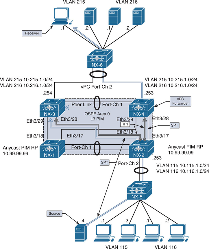
Figure 13-21 vPC-Connected Receiver Topology
The configuration is not modified in any way from the vPC-connected source example, with the exception of one command. The ip pim pre-build-spt command was configured on both NX-4 and NX-3. When configured, both vPC peers initiate an SPT join for each source, but only the elected forwarder forwards traffic toward vPC-connected receivers. The purpose of this command is to allow for faster failover in case the current vPC forwarder suddenly stops sending traffic as the result of a failure condition.
This configuration consumes additional bandwidth and additional replication of traffic in the network because the non-forwarder does not prune itself from the SPT. It continues to receive and discard the traffic until it detects the failure of the current forwarder. If this occurs, no delay is imposed by having to join the SPT. The traffic is there already waiting for the failure event to occur. In most environments, the benefits outweigh the cost, so using ip pim pre-build-spt is recommended for vPC environments.
When the multicast source 10.115.1.4 begins sending traffic to the group 239.115.115.1, the traffic is forwarded by L2 switch NX-5 to NX-2. Upon receiving the traffic, NX-2 creates an (S, G) entry for the traffic. Because no receivers exist yet, the OIL is empty at this time. However, NX-2 informs NX-1 about the source using a PIM register message because NX-1 and NX-2 are configured as PIM anycast RPs in the same RP set.
The receiver is 10.215.1.1 and is attached to the network in vPC VLAN 215. NX-6 forwards the IGMP membership report message to its mrouter port on Port-channel 2. This message can hash to either NX-3 or NX-4. When NX-4 receives the message, IGMP creates a (*, G) mroute entry. The membership report from the receiver is then sent across the peer link to NX-3, along with a corresponding CFS message. Upon receiving the message, NX-3 also creates a (*, G) mroute entry. Example 13-94 shows the IGMP snooping state, IGMP group state, and mroute on NX-4.
Example 13-94 IGMP State on NX-4
Type: S - Static, D - Dynamic, R - Router port, F - Fabricpath core port
Vlan Group Address Ver Type Port list
215 */* - R Vlan215 Po1 Po2
215 239.115.115.1 v2 D Po2
NX-4# show ip igmp groups
IGMP Connected Group Membership for VRF "default" - 1 total entries
Type: S - Static, D - Dynamic, L - Local, T - SSM Translated
Group Address Type Interface Uptime Expires Last Reporter
239.115.115.1 D Vlan215 2d18h 00:04:19 10.215.1.1
NX-4# show ip igmp internal vpc
IGMP chassis role is known
IGMP chassis role: Primary (cached Primary)
IGMP vPC Domain ID: 2
IGMP vPC Domain ID Configured: TRUE
IGMP vPC Peer-link Exclude feature enabled
IGMP emulated-switch id not configured
VPC Incremental type: no vpc incr upd, no proxy reporting, just sync (2)
Configured type: none (0)
VPC Incremental Once download: False
IGMP Vinci Fabric Forwarding DOWN
Implicit adding router for Vinci: Enabled
IGMP single DR: FALSE
NX-4# show ip mroute
IP Multicast Routing Table for VRF "default"
(*, 239.115.115.1/32), uptime: 00:00:04, igmp ip pim
Incoming interface: Ethernet3/28, RPF nbr: 10.2.23.2
Outgoing interface list: (count: 1)
Vlan215, uptime: 00:00:04, igmp
Example 13-95 shows the output from NX-3 after receiving the CFS messages from NX-4. Both vPC peers are synchronized to the same IGMP state, and IGMP is correctly registered with the vPC manager process.
Example 13-95 IGMP State on NX-3
Type: S - Static, D - Dynamic, R - Router port, F - Fabricpath core port
Vlan Group Address Ver Type Port list
215 */* - R Vlan215 Po1 Po2
215 224.0.1.40 v2 D Po2
215 239.115.115.1 v2 D Po2
NX-3# show ip igmp groups
IGMP Connected Group Membership for VRF "default" - 1 total entries
Type: S - Static, D - Dynamic, L - Local, T - SSM Translated
Group Address Type Interface Uptime Expires Last Reporter
239.115.115.1 D Vlan215 2d18h 00:04:13 10.215.1.1
NX-3# show ip igmp internal vpc
IGMP chassis role is known
IGMP chassis role: Secondary (cached Secondary)
IGMP vPC Domain ID: 2
IGMP vPC Domain ID Configured: TRUE
IGMP vPC Peer-link Exclude feature enabled
IGMP emulated-switch id not configured
VPC Incremental type: no vpc incr upd, no proxy reporting, just sync (2)
Configured type: none (0)
VPC Incremental Once download: False
IGMP Vinci Fabric Forwarding DOWN
Implicit adding router for Vinci: Enabled
IGMP single DR: FALSE
NX-3# show ip mroute
IP Multicast Routing Table for VRF "default"
(*, 239.115.115.1/32), uptime: 00:00:09, igmp ip pim
Incoming interface: Ethernet3/28, RPF nbr: 10.1.23.2
Outgoing interface list: (count: 1)
Vlan215, uptime: 00:00:09, igmp
The number of CFS messages sent between NX-3 and NX-4 can be seen in the output of show ip igmp snooping statistics (see Example 13-96). CFS is used to synchronize IGMP state and allows each vPC peer to communicate and elect a forwarder for each source.
Example 13-96 IGMP Snooping Statistics on NX-4
Global IGMP snooping statistics: (only non-zero values displayed)
Packets received: 43815
Packets flooded: 21828
vPC PIM DR queries fail: 3
vPC PIM DR updates sent: 6
vPC CFS message response sent: 15
vPC CFS message response rcvd: 11
vPC CFS unreliable message sent: 3688
vPC CFS unreliable message rcvd: 28114
vPC CFS reliable message sent: 11
vPC CFS reliable message rcvd: 15
STP TCN messages rcvd: 588
Note
IGMP control plane packet activity is seen in the output of show ip igmp snooping internal event-history vpc.
PIM joins are sent toward the RP from both NX-3 and NX-4, which can be seen in the show ip pim internal event-history join-prune output of Example 13-97.
Example 13-97 (*, G) Join from NX-4 and NX-3
21:31:32.075044 pim [10572]:: Send Join-Prune on Ethernet3/28, length: 34
21:31:32.075016 pim [10572]:: Put (*, 239.115.115.1/32), WRS in join-list
NX-3# show ip pim internal event-history join-prune
21:31:32.193593 pim [10975]:: Put (*, 239.115.115.1/32), WRS in join-list
Upon receiving the (*, G) join messages from NX-3 and NX-4, the mroute entry on NX-2 is updated to include the Ethernet 3/17 and Ethernet 3/18 interfaces to NX-3 and NX-4 in the OIL. Traffic then is sent out on the RPT.
As the traffic arrives on the RPT at NX-3 and NX-4, the source address of the group traffic becomes known, which triggers the creation of the (S, G) mroute entry. NX-3 and NX-4 then determine which device will act as the forwarder for this source using CFS. The communication for the forwarder election is viewed in the output of show ip pim internal event-history vpc. Because both NX-3 and NX-4 have equal metrics and route preference to the source, a tie occurs. However, because NX-4 is the vPC primary, it wins over NX-3 and acts as the forwarder for 10.115.1.4.
After the election results are obtained, an entry is created in the vPC RPF-Source cache, which is seen with the show ip pim internal vpc rpf-source command. Example 13-98 contains the PIM vPC forwarding election output from NX-4 and NX-3.
Example 13-98 PIM vPC Forwarder Election on NX-3 and NX-4
21:31:33.795803 pim [10572]: RPF-source 10.115.1.4 state changed to
for source 10.115.1.4, rpf-interface Ethernet3/28
21:31:33.743829 pim [10572]: Trigger handshake for rpf-source metrices for VRF
10.115.1.4
21:31:33.743639 pim [10572]: Created vPC RPF-source entry for 10.115.1.4 upon
NX-3# show ip pim internal event-history vpc
for source 10.115.1.4, rpf-interface Ethernet3/28
21:31:33.912607 pim [10975]: Trigger handshake for rpf-source metrices for VRF
10.115.1.4
21:31:33.912501 pim [10975]: Created vPC RPF-source entry for 10.115.1.4 upon
Source: 10.115.1.4
Pref/Metric: 110/44
Ref count: 1
In MRIB: yes
Is (*,G) rpf: no
Source role: primary
Forwarding state: Tie (forwarding)
MRIB Forwarding state: forwarding
NX-3# show ip pim internal vpc rpf-source
PIM vPC RPF-Source Cache for Context "default" - Chassis Role Secondary
Source: 10.115.1.4
Pref/Metric: 110/44
Ref count: 1
In MRIB: yes
Is (*,G) rpf: no
Source role: secondary
Forwarding state: Tie (not forwarding)
MRIB Forwarding state: not forwarding
For this election process to work correctly, PIM must be registered with the vPC manager process. This is indicated in the highlighted output of Example 13-99.
Example 13-99 PIM vPC Status on NX-4
PIM CFS sync start: yes
VPC peer link is up on port-channel1
PIM vPC Operating Version: 2
PIM chassis role is known
PIM chassis role: Primary (cached Primary)
PIM vPC Domain ID: 2
PIM emulated-switch id not configured
PIM vPC Domain Id Configured: yes
With ip pim pre-build-spt, both NX-3 and NX-4 initiate (S, G) joins toward NX-2 following the RPF path toward the source. However, because NX-3 is not the forwarder, it simply discards the packets it receives on the SPT. NX-4 forwards packets toward the vPC receiver and across the peer link to NX-3.
Example 13-100 shows the (S, G) mroute state and resulting PIM SPT joins from NX-3 and NX-4. Only NX-4 has an OIL containing VLAN 215 for the (S, G) mroute entry.
Example 13-100 PIM (S, G) Join Events and MROUTE State
21:31:33.743825 pim [10572]:: Put (10.115.1.4/32, 239.115.115.1/32), S in
join-list for nbr 10.2.23.2
21:31:33.743818 pim [10572]:: wc_bit = FALSE, rp_bit = FALSE
NX-3# show ip pim internal event-history join-prune
! Output omitted for brevity
21:31:33.913795 pim [10975]:: Send Join-Prune on Ethernet3/28, length: 34
21:31:33.912603 pim [10975]:: Put (10.115.1.4/32, 239.115.115.1/32), S in
join-list for nbr 10.1.23.2
21:31:33.912597 pim [10975]:: wc_bit = FALSE, rp_bit = FALSE
NX-4# show ip mroute
(*, 239.115.115.1/32), uptime: 00:07:08, igmp ip pim
Incoming interface: Ethernet3/28, RPF nbr: 10.2.23.2
Outgoing interface list: (count: 1)
Vlan215, uptime: 00:07:08, igmp
(10.115.1.4/32, 239.115.115.1/32), uptime: 00:07:06, ip mrib pim
Incoming interface: Ethernet3/28, RPF nbr: 10.2.23.2
Outgoing interface list: (count: 1)
Vlan215, uptime: 00:07:06, mrib
NX-3# show ip mroute
(*, 239.115.115.1/32), uptime: 00:06:05, igmp ip pim
Incoming interface: Ethernet3/28, RPF nbr: 10.1.23.2
Outgoing interface list: (count: 1)
Vlan215, uptime: 00:06:05, igmp
(10.115.1.4/32, 239.115.115.1/32), uptime: 00:06:03, ip mrib pim
Incoming interface: Ethernet3/28, RPF nbr: 10.1.23.2
Outgoing interface list: (count: 1)
More detail about the mroute state is seen in the output of the show routing ip multicast source-tree detail command. This command provides additional information that can be used for verification. The output confirms that NX-4 is the RPF-Source Forwarder for this (S, G) entry (see Example 13-101). NX-3 has the same OIL, but its status is set to inactive, which indicates that it is not forwarding.
Example 13-101 Multicast Source Tree Detail on NX-4 and NX-3
Total number of routes: 3
Total number of (*,G) routes: 1
Total number of (S,G) routes: 1
Total number of (*,G-prefix) routes: 1
(10.115.1.4/32, 239.115.115.1/32) Route ptr: 0x5ced35b4 , uptime: 00:14:50,
ip(0) mrib(1) pim(0)
RPF-Source: 10.115.1.4 [44/110]
Data Created: Yes
Stats: 422/37162 [Packets/Bytes], 352.000 bps
Incoming interface: Ethernet3/28, RPF nbr: 10.2.23.2
IP Multicast Routing Table for VRF "default"
Total number of routes: 3
Total number of (*,G) routes: 1
Total number of (S,G) routes: 1
Total number of (*,G-prefix) routes: 1
(10.115.1.4/32, 239.115.115.1/32) Route ptr: 0x5cfd46b0 , uptime: 00:15:14,
ip(0) mrib(1) pim(0)
RPF-Source: 10.115.1.4 [44/110]
Data Created: Yes
Stats: 440/38746 [Packets/Bytes], 352.000 bps
Stats: 440/38746 [Packets/Bytes], 352.000 bps
Incoming interface: Ethernet3/28, RPF nbr: 10.1.23.2
The behavioral differences from traditional multicast must be understood to troubleshoot multicast in a vPC environment effectively. The use of (*, G) and (S, G) mroute state and knowledge on how the IIF and OIL are populated are key to determining which vPC peer to focus on when troubleshooting.
vPC Considerations for Multicast Traffic
Additional considerations with multicast traffic in a vPC environment should be understood. The considerations mentioned here might not apply to every network, but they are common enough that they should be considered when implementing vPC and multicast together.
Duplicate Multicast Packets
In some network environments, it may be possible to observe duplicate frames momentarily when multicast traffic is combined with vPC. These duplicate frames are generally seen only during the initial state transitions, such as when switching to the SPT tree. If the network applications are extremely sensitive to this and cannot deal with any duplicate frames, the following actions are recommended:
Increase the PIM SG-Expiry timer with the ip pim sg-expiry-timer command. The value should be sufficiently large so that the (S, G) state does not time out during business hours.
Configure ip pim pre-build-spt.
Use multicast source-generated probe packets to populate the (S, G) state in the network before each business day.
The purpose of these steps is to have the SPT trees built before any business-critical data is sent each day. The increased (S, G) expiry timer allows the state to remain in place during critical times and avoid state timeout and re-creation for intermittent multicast senders. This avoids state transitions and the potential for duplicate traffic.
Reserved VLAN
The Nexus 5500 and Nexus 6000 series platforms utilize a reserved VLAN for the purposes of multicast routing when vPC is configured. When traffic arrives from a vPC-connected source, the following events occur:
The traffic is replicated to any receivers in the same VLAN, including the peer link.
The traffic is routed to any receivers in different vPC VLANs.
A copy is sent across the peer link using the reserved VLAN.
As packets arrive from the peer link at the vPC peer, if the traffic is received from any VLAN except for the reserved VLAN, it will not be multicast routed. If the vpc bind-vrf [vrf name] vlan [VLAN ID] is not configured on both vPC peers, orphan ports or L3-connected receivers will not receive traffic. This command must be configured for each VRF participating in multicast routing.
Ethanalyzer Examples
Various troubleshooting steps in this chapter have relied on the NX-OS Ethanalyzer facility to capture control plane protocol messages. Table 13-11 provides examples of Ethanalyzer protocol message captures for the purposes of troubleshooting. In general, when performing an Ethanalyzer capture, you must decide whether the packets should be displayed in the session, decoded in the session, or written to a local file for offline analysis. The basic syntax of the command is ethanalyzer local interface [inband] capture-filter [filter-string in quotes] write [location:filename]. Many variations of the command exist, depending on which options are desired.
Table 13-11 Example Ethanalyzer Captures
What Is Being Captured |
Ethanalyzer Capture Filter |
Packets that are PIM and to/from host 10.2.23.3. |
“pim && host 10.2.23.3” |
Unicast PIM packets such as register or candidate RP advertisement |
“pim && not host 224.0.0.13” |
MSDP messages from 10.1.1.1 |
“src host 10.1.1.1 && tcp port 639” |
IGMP general query |
“igmp && host 224.0.0.1” |
IGMP group specific query or report message |
“igmp && host 239.115.115.1” |
IGMP leave message |
“igmp && host 224.0.0.2” |
Multcast data packets sent to the supervisor from 10.115.1.4 |
“src host 10.115.1.4 && dst host 239.115.115.1” |
Ethanalyzer syntax might vary slightly, depending on the platform. For example, some NX-OS platforms such as Nexus 3000 have inband-hi and inband-lo interfaces. For most control plane protocols, the packets are captured on the inband-hi interface. However, if the capture fails to collect any packets, the user might need to try a different interface option.
Summary
Multicast communication using NX-OS was covered in detail throughout this chapter. The fundamental concepts of multicast forwarding were introduced before delving into the NX-OS multicast architecture. The IGMP and PIM protocols were examined in detail to build a foundation for the detailed verification examples. The supported PIM operating modes (ASM, BiDIR, and SSM) were explored, including the various message types used for each and the process for verifying each type of multicast distribution tree. Finally, multicast and vPC were reviewed and explained, along with the differences in protocol behavior that are required when operating in a vPC environment. The goal of this chapter was not to cover every possible multicast forwarding scenario, but instead to provide you with a toolbox of fundamental concepts that can be adapted to a variety of troubleshooting situations in a complex multicast environment.
References
RFC 1112, Host Extensions for IP Multicasting, S. Deering. IETF, https://tools.ietf.org/html/rfc1112, August 1989.
RFC 2236, Internet Group Management Protocol, Version 2, W. Fenner. IETF, https://tools.ietf.org/html/rfc2236, November 1997.
RFC 3376, Internet Group Management Protocol, Version 3, B. Cain, S. Deering, I. Kouvelas, et al. IETF, https://www.ietf.org/rfc/rfc3376.txt, October 2002.
RFC 3446, Anycast Rendezvous Point (RP) Mechanism Using Protocol Independent Multicast (PIM) and Multicast Source Discovery Protocol (MSDP). D. Kim, D. Meyer, H. Kilmer, D. Farinacci. IETF, https://www.ietf.org/rfc/rfc3446.txt, January 2003.
RFC 3618, Multicast Source Discovery Protocol (MSDP). B. Fenner, D. Meyer. IETF, https://www.ietf.org/rfc/rfc3618.txt, October 2003.
RFC 4541, Considerations for Internet Group Management Protocol (IGMP) and Multicast Listener Discovery (MLD) Snooping Switches. M. Christensen, K. Kimball, F. Solensky. IETF, https://www.ietf.org/rfc/rfc4541.txt, May 2006.
RFC 4601, Protocol Independent Multicast–Sparse Mode (PIM-SM): Protocol Specification (Revised). B. Fenner, M. Handley, H. Holbrook, I. Kouvelas. IETF, https://www.ietf.org/rfc/rfc4601.txt, August 2006.
RFC 4607, Source-Specific Multicast for IP. H. Holbrook, B. Cain. IETF, https://www.ietf.org/rfc/rfc4607.txt, August 2006.
RFC 4610, Anycast-RP Using Protocol Independent Multicast (PIM). D. Farinacci, Y. Cai. IETF, https://www.ietf.org/rfc/rfc4610.txt, August 2006.
RFC 5015, Bidirectional Protocol Independent Multicast (BIDIR-PIM). M. Handley, I. Kouvelas, T. Speakman, L. Vicisano. IETF, https://www.ietf.org/rfc/rfc5015.txt, October 2007.
RFC 5059, Bootstrap Router (BSR) Mechanism for Protocol Independent Multicast (PIM). N. Bhaskar, A. Gall, J. Lingard, S. Venaas. IETF, https://www.ietf.org/rfc/rfc5059.txt, January 2008.
RFC 5771, IANA Guidelines for IPv4 Multicast Address Assignments. M. Cotton, L. Vegoda, D. Meyer. IETF, https://tools.ietf.org/rfc/rfc5771.txt, March 2010.
RFC 6166, A Registry for PIM Message Types. S. Venaas. IETF, https://tools.ietf.org/rfc/rfc6166.txt, April 2011.
Cisco NX-OS Software Configuration Guides. http://www.cisco.com.
Doyle, Jeff, and Jennifer DeHaven Carroll. Routing TCP/IP, Volume II (Indianapolis: Cisco Press, 2001).
Edgeworth, Brad, Aaron Foss, and Ramiro Garza Rios. IP Routing on Cisco IOS, IOS XE and IOS XR (Indianapolis: Cisco Press, 2014).
Esau, Matt. “Troubleshooting NXOS Multicast” (Cisco Live: San Francisco, 2014.)
Fuller, Ron, David Jansen, and Matthew McPherson. NX-OS and Cisco Nexus Switching (Indianapolis: Cisco Press, 2013).
IPv4 Multicast Address Space Registry, Stig Venaas, http://www.iana.org/assignments/multicast-addresses/multicast-addressess.xhtml, October 2017.
Loveless, Josh, Ray Blair, and Arvind Durai. IP Multicast, Volume I: Cisco IP Multicast Networking (Indianapolis: Cisco Press, 2016).