Chapter 5
Port-Channels, Virtual Port-Channels, and FabricPath
This chapter covers the following topics:
Virtual Port-Channel Plus (vPC+)
Proper network design takes into account single points of failure by ensuring that alternate paths and devices can forward traffic in case of failure. Routing protocols make sure that redundant paths can still be consumed because of equal-cost multipath (ECMP). However, Spanning Tree Protocol (STP) stops forwarding on redundant links between switches to prevent forwarding loops.
Although STP is beneficial, it limits the amount of bandwidth to be achieved between switches. Port-channels provide a way to combine multiple physical links into a virtual link to increase bandwidth because all the member interfaces can forward network traffic. This chapter explains port-channel operations and the techniques to troubleshoot port-channels when they do not operate as intended.
Port-Channels
Port-channels are a logical link that consists of one or multiple physical member links. Port-channels are defined in the IEEE 803.3AD Link Aggregation Specification and are sometimes referred to as EtherChannels. The physical interfaces that are used to assemble the logical port-channel are called member interfaces. Port-channels are either Layer 2 (L2) switching or Layer 3 (L3) routing.
Figure 5-1 visualizes some of the key components of a port-channel (member interface and logical interface), along with the advantages it provides over individual links. A primary advantage of using port-channels is the reduction of topology changes when a member link is added or removed for a port-channel. A change might trigger an L2 STP tree calculation or L3 SPF calculation, but forwarding still occurs between the devices in the port-channel.

Figure 5-1 Advantages of Port-Channels Versus Individual Links
Nexus switches successfully form a port-channel by statically setting them to an “on” state or by using link-aggregation control packets (LACP) to detect connectivity between devices. Most network engineers prefer to use LACP because it ensures end-to-end connectivity between devices. LACP provides a method to detect failures with unidirectional links for member interfaces or identify when other devices are in the path (for example, dense wavelength-division multiplexing [DWDM] devices that do not support link propagation).
In Figure 5-2, NX-1 and NX-2 have combined their Ethernet1/1 and Ethernet1/2 interfaces into Port-Channel1. A failure on Link-A between the optical transport devices DWDM-1 and DWDM-2 is not propagated to the Eth1/1 interface on NX-1 or NX-2. The Nexus switches continue to forward traffic out the Eth1/1 interface because those ports still maintain physical state to DWDM-1 or DWDM-2. There is not a health-check mechanism with the port-channel ports being statically set to “on.” However, if LACP was configured, NX-1 and NX-2 would detect that traffic cannot flow end-to-end on the upper path and would remove that link from the logical port-channel.

Figure 5-2 Port-Channel Link State Propagation and Detection
A member link becomes active within a port-channel after establishing an LACP using the following messages:
Sync (S): Initial flag, indicating that the local switch includes the member interface as part of the port-channel
Collecting (C): Second flag, indicating that the local switch processes network traffic that is received on this interface
Distributing (D): Third flag, indicating that the local switch transmits network traffic using this member interface
When a port comes up, messages are exchanged following these steps:
Step 1. Both switches (source and destination) advertise LACP packets with the Sync, Collecting, and Distributing flags set to zero (off).
Step 2. As the source switch receives an LACP packet from the destination switch, it collects the system-ID and port-ID from the initial LACP packet. The source switch then transmits a Sync LACP packet indicating that it is willing to participate in the port-channel. The initial LACP Sync packet includes the local system-ID, port-ID, and port-priority, along with the detected remote switches’ information (system-ID, port-ID, and port-priority). LACP members for the port-channel are selected at this time.
The destination switch repeats this step as well.
Step 3. Upon receipt of the Sync LACP packet, the source switch verifies that the local and remote (destination switch) system-IDs match the Sync LACP packets to ensure that the switch-ID is the same across all member links and that no multiple devices exist on a link (that is, no device is operating in the middle, providing connectivity to a third switch). The source switch then transmits a Collecting LACP packet indicating that the source switch is ready to receive traffic on that interface.
Step 4. The destination switch verifies the accuracy of the Sync LACP packet for the source switch against what was performed by the source switch. The destination switch then sends a Collecting LACP packet indicating that the destination switch is ready to receive traffic on that interface.
Step 5. The source switch receives the Collecting LACP packet from the destination switch and transmits a Distributing LACP packet to the destination switch indicating that it is transmitting data across that member link.
Step 6. The destination switch receives the Collecting LACP packet from the source switch and transmits a Distributing LACP packet to the source switch indicating that it is transmitting data across that member link.
Step 7. Both switches transmit data across the member link interface that has completed the previous steps successfully.
Note
The LACP packets in Step 7 happen independently of other switches, assuming that the requirements are met.
Figure 5-3 demonstrates the exchange of LACP messages between NX-1 (source switch) and NX-2 (destination switch).

Figure 5-3 LACP Negotiation
Note
This process occurs on every member link when it joins a port-channel interface.
Basic Port-Channel Configuration
Port-channels are configured by going into interface configuration mode for the member interfaces and then assigning them to a port-channel and statically setting them to “on,” or with LACP dynamic negotiation. LACP operates with two modes:
Passive: An interface does not initiate a port-channel to be established and does not transmit LACP packets out of it. If the remote switch receives an LACP packet, this interface responds and then establishes an LACP adjacency. If both devices are LACP passive, no LACP adjacency forms.
Active: An interface tries to initiate a port-channel establishment and transmits LACP packets out of it. Active LACP interfaces can establish an LACP adjacency only if the remote interface is configured to active or passive.
The LACP feature must first be enabled with the global command feature lacp. Then the interface parameter command channel-group portchannel-number mode {on | active | passive} converts a regular interface into a member interface.
Example 5-1 demonstrates the configuration port-channel 1 using the member interfaces Eth1/1 and Eth1/2. Notice that the port-channel is configured as a trunk interface, not as the individual member interfaces.
Example 5-1 Sample Port-Channel Configuration
Enter configuration commands, one per line. End with CNTL/Z.
NX-1(config)# feature lacp
NX-1(config)# interface ethernet 1/1-2
NX-1(config-if-range)# channel-group 1 mode active
03:53:14 NX-1 %$ VDC-1 %$ %ETHPORT-5-IF_DOWN_CHANNEL_MEMBERSHIP_UPDATE_IN_PROGRESS: Interface Ethernet1/2 is down (Channel membership update in progress)
03:53:14 NX-1 %$ VDC-1 %$ %ETHPORT-5-IF_DOWN_CHANNEL_MEMBERSHIP_UPDATE_IN_PROGRESS: Interface Ethernet1/1 is down (Channel membership update in progress)
03:53:16 NX-1 %$ VDC-1 %$ %ETHPORT-5-IF_DUPLEX: Interface port-channel1, operational duplex mode changed to Full
03:53:21 NX-1 %$ VDC-1 %$ %ETH_PORT_CHANNEL-5-PORT_UP: port-channel1: Ethernet1/1 is up
03:53:21 NX-1 %$ VDC-1 %$ %ETH_PORT_CHANNEL-5-FOP_CHANGED: port-channel1: first operational port changed from none to Ethernet1/1
03:53:21 NX-1 %$ VDC-1 %$ %ETH_PORT_CHANNEL-5-PORT_UP: port-channel1: Ethernet1/2 is up
03:53:21 NX-1 %$ VDC-1 %$ %ETHPORT-5-IF_UP: Interface Ethernet1/1 is up in mode access
03:53:21 NX-1 %$ VDC-1 %$ %ETHPORT-5-IF_UP: Interface port-channel1 is up in mode access
03:53:21 NX-1 %$ VDC-1 %$ %ETHPORT-5-IF_UP: Interface Ethernet1/2 is up in mode access
NX-1(config-if-range)# interface port-channel 1
NX-1(config-if)# switchport mode trunk
03:53:21 NX-1 %$ VDC-1 %$ %ETH_PORT_CHANNEL-5-PORT_DOWN: port-channel1: Ethernet1/1 is down
03:53:21 NX-1 %$ VDC-1 %$ %ETH_PORT_CHANNEL-5-PORT_DOWN: port-channel1: Ethernet1/2 is down
..
03:53:29 NX-1 %$ VDC-1 %$ %ETH_PORT_CHANNEL-5-PORT_UP: port-channel1: Ethernet1/1 is up
03:53:29 NX-1 %$ VDC-1 %$ %ETH_PORT_CHANNEL-5-FOP_CHANGED: port-channel1: first operational port changed from none to Ethernet1/1
03:53:29 NX-1 %$ VDC-1 %$ %ETH_PORT_CHANNEL-5-PORT_UP: port-channel1: Ethernet1/2 is up
03:53:29 NX-1 %$ VDC-1 %$ %ETHPORT-5-IF_UP: Interface Ethernet1/1 is up in mode trunk
03:53:29 NX-1 %$ VDC-1 %$ %ETHPORT-5-IF_UP: Interface port-channel1 is up in mode trunk
03:53:29 NX-1 %$ VDC-1 %$ %ETHPORT-5-IF_UP: Interface Ethernet1/2 is up in mode trunk
Verifying Port-Channel Status
Now that the port-channel is configured, verifying that the port-channel is established is essential. The command show port-channel summary provides an overview of all configured port-channels and their status. Example 5-2 displays the use of this command.
Example 5-2 Viewing Port-Channel Summary Status
Flags: D - Down P - Up in port-channel (members)
I - Individual H - Hot-standby (LACP only)
s - Suspended r - Module-removed
S - Switched R - Routed
U - Up (port-channel)
p - Up in delay-lacp mode (member)
M - Not in use. Min-links not met
--------------------------------------------------------------------------------
Group Port- Type Protocol Member Ports
Channel
--------------------------------------------------------------------------------
1 Po1(SU) Eth LACP Eth1/1(P) Eth1/2(P)
When viewing the output of the show port-channel summary command, check the port-channel status, which is listed below the port-channel interface. The status should be “U,” as in Example 5-2.
Examine Table 5-1 to understand the port-channel flags.
Table 5-1 Logical Port-Channel Interface Status Fields
Field |
Description |
U |
The port-channel interface is working properly. |
D |
The port-channel interface is down. |
M |
The port-channel interface has successfully established at least one LACP adjacency. However, the port-channel is configured to have a minimum number of active interfaces that exceeds the number of active participating member interfaces. Traffic does not forward across this port-channel. The command lacp min-links number-member-interfaces is configured on the port-channel interface. |
S |
The port-channel interface is configured for Layer 2 (L2) switching. |
R |
The port-channel interface is configured for Layer 3 (L3) routing. |
Table 5-2 briefly explains the fields related to the member interfaces.
Table 5-2 Port-Channel Member Interface Status Fields
Field |
Description |
P |
The interface is actively participating and forwarding traffic for this port-channel. |
H |
The port-channel is configured with the maximum number of active interfaces. This interface is participating with LACP with the remote peer, but it is acting as a hot-standby and does not forward traffic. The command lacp max-bundle number-member-interfaces is configured on the port-channel interface. |
I |
The member interface is treated as an individual and does not detect any LACP activity on this interface. |
w |
This field indicates the time left to receive a packet from this neighbor to ensure that it is still alive. |
s |
The member interface is in a suspended state. |
r |
The switch module associated with this interface has been removed from the chassis. |
The logical interface is viewed with the command show interface port-channel port-channel-id. The output includes data fields that are typically displayed with a traditional Ethernet interface, with the exception of the member interfaces and the fact that the bandwidth reflects the combined throughput of all active member interfaces. As this changes, factors such as QoS policies and interface costs for routing protocols adjust accordingly.
Example 5-3 displays the use of the command on NX-1. Notice that the bandwidth is 20 Gbps and correlates to the two 10-Gbps interfaces in the port-channel interface.
Example 5-3 Viewing Port-Channel Interface Status
admin state is up,
Hardware: Port-Channel, address: 885a.92de.6158 (bia 885a.92de.6158)
MTU 1500 bytes, BW 20000000 Kbit, DLY 10 usec
reliability 255/255, txload 1/255, rxload 1/255
Encapsulation ARPA, medium is broadcast
Input flow-control is off, output flow-control is off
Auto-mdix is turned off
Switchport monitor is off
EtherType is 0x8100
Members in this channel: Eth1/1, Eth1/2
..
Verifying LACP Packets
NX-OS logging provides many relevant syslog messages to identify configuration incompatibilities. A vital step in troubleshooting the establishment of port-channels is to verify that LACP packets are being transmitted between devices. The first troubleshooting step is to verify the LACP counters using the command show lacp counters [interface port-channel port-channel-number].
The output includes a list of the port-channel interfaces, their associated member interfaces, counters for LACP packets sent/received, and any errors. An interface should see the Sent and Received columns increment over a time interval. If the counters do not increment, this indicates a problem. The problem could be related to the physical link or an incomplete/incompatible configuration with the remote device. Check the LACP counters on that device to see if it is transmitting LACP packets.
Example 5-4 demonstrates the command. Notice that the Received column does not increment on Ethernet1/2 for port-channel 1, but it does increment on the Sent column.
Example 5-4 Viewing LACP Packet Counters
NOTE: Clear lacp counters to get accurate statistics
------------------------------------------------------------------------------
LACPDUs Markers/Resp LACPDUs
Port Sent Recv Recv Sent Pkts Err
------------------------------------------------------------------------------
port-channel1
Ethernet1/1 5753 5660 0 0 0
Ethernet1/2 5319 0 0 0 0
NOTE: Clear lacp counters to get accurate statistics
------------------------------------------------------------------------------
LACPDUs Markers/Resp LACPDUs
Port Sent Recv Recv Sent Pkts Err
------------------------------------------------------------------------------
port-channel1
Ethernet1/1 5755 5662 0 0 0
Ethernet1/2 5321 0 0 0 0
Another method involves using the command show lacp internal info interface interface-id. This command includes a time stamp for the last time a packet was transmitted or received out of an interface. Example 5-5 demonstrates the use of this command.
Example 5-5 Viewing Time Stamps for LACP Transmissions on an Interface
Interface Ethernet1/1(0x1a030000) info
--------------------------------------
port_pr 0x8000
rid type IF-Rid: ifidx 0x1a030000: ch_num 0
cfg_pc_if_idx 0x16000000: oper_pc_if_idx 0x16000000
is state_change_notif_pending 0
lacp detected link down 0
lag [(8000, 0-62-ec-9d-c5-0, 1, 8000, 11c), (8000, 88-5a-92-de-61-7c, 8000, 8000, 131)]
aggr_id 0x0
MARKER RESP sent at: None.
ERROR PDU sent at : None.
MARKER PDU recv at : None.
ERROR PDU recv at : None.
The command show lacp neighbor [interface port-channel port-channel-number] displays additional information about the port-channel interface, its member interfaces, and the remote device on a link-by-link basis.
Example 5-6 demonstrates the use of this command. The output includes the neighbor’s system ID, system priority, remote port number, remote port-priority, and details on whether it is using fast or slow LACP packet intervals.
Example 5-6 Viewing LACP Neighbor Information
Flags: S - Device is sending Slow LACPDUs F - Device is sending Fast LACPDUs
A - Device is in Active mode P - Device is in Passive mode
port-channel1 neighbors
Partner's information
Port System ID Port Number Age Flags
Eth1/1 32768,18-9c-5d-11-99-800x138 985 SA
Port Priority Oper Key Port State
32768 0x1 0x3d
Partner's information
Partner Partner Partner
Port System ID Port Number Age Flags
Eth1/2 32768,18-9c-5d-11-99-800x139 985 SA
LACP Partner Partner Partner
Port Priority Oper Key Port State
32768 0x1 0x3d
Note
Use the LACP system identifier to verify that the member interfaces are connected to the same device and are not split between devices. The local LACP system-ID is viewed using the command show lacp system-identifier.
The NX-OS Ethanalyzer tool is used to view the LACP packets being transmitted and received on the local Nexus switch by capturing packets with the LACP MAC destination address. The command ethanalyzer local interface inband capture-filter "ether host 0180.c200.0002" [detail] captures LACP packets that are received. The optional detail keyword provides additional information. Example 5-7 demonstrates the technique.
Example 5-7 Capturing LACP Packets with Ethanalyzer
Capturing on inband
2017-10-23 03:58:11.213625 88:5a:92:de:61:58 -> 01:80:c2:00:00:02 LACP Link Aggr
egation Control Protocol
2017-10-23 03:58:11.869668 88:5a:92:de:61:59 -> 01:80:c2:00:00:02 LACP Link Aggr
egation Control Protocol
2017-10-23 03:58:23.381249 00:62:ec:9d:c5:1c -> 01:80:c2:00:00:02 LACP Link Aggr
egation Control Protocol
2017-10-23 03:58:24.262746 00:62:ec:9d:c5:1b -> 01:80:c2:00:00:02 LACP Link Aggr
egation Control Protocol
2017-10-23 03:58:41.218262 88:5a:92:de:61:58 -> 01:80:c2:00:00:02 LACP Link Aggr
egation Control Protocol
Advanced LACP Configuration Options
The following section explains some of the advanced LACP configuration options and their behavioral impact on member interface selection for a port-channel.
Minimum Number of Port-Channel Member Interfaces
A port-channel interface becomes active and up when only one member interface successfully forms an LACP adjacency with a remote device. In some design scenarios, a minimum number of LACP adjacencies is required before a port-channel interface becomes active. This option is configured with the port-channel interface command lacp min-links min-links.
Example 5-8 demonstrates setting the minimum number of port-channel interfaces to two and then shutting down one of the member interfaces on NX-1. Notice that the port-channel status is “Not in use.”
Example 5-8 Configuring a Minimum Number of Port-Channel Member Interfaces
NX-1(config)# interface port-channel 1
NX-1(config-if)# lacp min-links 2
NX-1(config-if)# interface Eth1/1
NX-1(config-if)# shut
04:22:45 NX-1 %$ VDC-1 %$ %ETH_PORT_CHANNEL-5-PORT_DOWN: port-channel1: Ethernet1/1 is down
04:22:45 NX-1 %$ VDC-1 %$ %ETHPORT-5-IF_DOWN_CFG_CHANGE: Interface Ethernet1/1 is down(Config change)
04:22:45 NX-1 %$ VDC-1 %$ %ETHPORT-5-IF_DOWN_ADMIN_DOWN: Interface Ethernet1/1 is down (Administratively down)
04:22:47 NX-1 %$ VDC-1 %$ %ETHPORT-5-IF_DOWN_PORT_CHANNEL_MEMBERS_DOWN: Interface port-channel1 is down (No operational members)
04:22:47 NX-1 %$ VDC-1 %$ %ETH_PORT_CHANNEL-5-PORT_DOWN: port-channel1: Ethernet1/2 is down
04:22:47 NX-1 %$ VDC-1 %$ %ETH_PORT_CHANNEL-5-FOP_CHANGED: port-channel1: first operational port changed from Ethernet1/2 to none
04:22:47 NX-1 %$ VDC-1 %$ %ETHPORT-5-IF_DOWN_INITIALIZING: Interface Ethernet1/2 is down (Initializing)
04:22:47 NX-1 %$ VDC-1 %$ %ETHPORT-5-IF_DOWN_PORT_CHANNEL_MEMBERS_DOWN: Interface port-channel1 is down (No operational members)
04:22:47 NX-1 %$ VDC-1 %$ %ETHPORT-5-SPEED: Interface port-channel1, operational speed changed to 10 Gbps
04:22:47 NX-1 %$ VDC-1 %$ %ETHPORT-5-IF_DUPLEX: Interface port-channel1, operational duplex mode changed to Full
04:22:47 NX-1 %$ VDC-1 %$ %ETHPORT-5-IF_RX_FLOW_CONTROL: Interface port-channel1, operational Receive Flow Control state changed to off
04:22:47 NX-1 %$ VDC-1 %$ %ETHPORT-5-IF_TX_FLOW_CONTROL: Interface port-channel1, operational Transmit Flow Control state changed to off
Flags: D - Down P - Up in port-channel (members)
I - Individual H - Hot-standby (LACP only)
s - Suspended r - Module-removed
S - Switched R - Routed
U - Up (port-channel)
p - Up in delay-lacp mode (member)
M - Not in use. Min-links not met
--------------------------------------------------------------------------------
Group Port- Type Protocol Member Ports
Channel
--------------------------------------------------------------------------------
1 Po1(SM) Eth LACP Eth1/1(D) Eth1/2(s)
Note
The minimum number of port-channel member interfaces does not need to be configured on both devices to work properly. However, configuring it on both switches is recommended to accelerate troubleshooting and assist operational staff.
Maximum Number of Port-Channel Member Interfaces
A port-channel can be configured to have a maximum number of member interfaces in a port-channel. This is a common design scenario to ensure that the active member interface count keeps with the power of twos (2, 4, 8, 16) to accommodate load-balancing hashes. The maximum number of member interfaces in a port-channel is configured with the port-channel interface command lacp max-bundle max-links.
Example 5-9 displays configuring the maximum number of active member interfaces for a port-channel and demonstrates that those interfaces now show as “Hot-Standby.”
Example 5-9 Configuration and Verification of Maximum Links
Enter configuration commands, one per line. End with CNTL/Z.
NX-1(config)# interface port-channel 2
NX-1(config-if)# lacp max-bundle 4
04:44:04 NX-1 %$ VDC-1 %$ %ETH_PORT_CHANNEL-5-PORT_DOWN: port-channel2: Ethernet1/7 is down
04:44:04 NX-1 %$ VDC-1 %$ %ETHPORT-5-IF_DOWN_INITIALIZING: Interface Ethernet1/7 is down (Initializing)
04:44:04 NX-1 %$ VDC-1 %$ %ETH_PORT_CHANNEL-5-PORT_DOWN: port-channel2: Ethernet1/8 is down
04:44:04 NX-1 %$ VDC-1 %$ %ETHPORT-5-IF_DOWN_INITIALIZING: Interface Ethernet1/8 is down (Initializing)
04:44:06 NX-1 %$ VDC-1 %$ %ETH_PORT_CHANNEL-5-PORT_HOT_STANDBY: port-channel2: Ethernet1/7 goes to hot-standby
04:44:06 NX-1 %$ VDC-1 %$ %ETH_PORT_CHANNEL-5-PORT_HOT_STANDBY: port-channel2: Ethernet1/8 goes to hot-standby
Flags: D - Down P - Up in port-channel (members)
I - Individual H - Hot-standby (LACP only)
s - Suspended r - Module-removed
S - Switched R - Routed
U - Up (port-channel)
p - Up in delay-lacp mode (member)
M - Not in use. Min-links not met
--------------------------------------------------------------------------------
Group Port- Type Protocol Member Ports
Channel
--------------------------------------------------------------------------------
1 Po1(SU) Eth LACP Eth1/1(P) Eth1/2(P)
2 Po2(SU) Eth LACP Eth1/3(P) Eth1/4(P) Eth1/5(P)
Eth1/6(P) Eth1/7(H) Eth1/8(H)
The maximum number of port-channel member interfaces can be configured on only one switch for that port-channel; however, configuring it on both switches is recommended to accelerate troubleshooting and assist operational staff. The interfaces show as “suspended” on the secondary switch.
The port-channel master switch controls which member interfaces (and associated links) are active by examining the LACP port priority. A lower port priority is preferred. If the port-priority is the same, the lower interface number is preferred.
LACP System Priority
The LACP system priority identifies which switch is the master switch for a port-channel. The master switch on a port-channel is responsible for choosing which member interfaces are active in a port-channel when the number of member interfaces is greater than the maximum number of member interfaces associated to a port-channel interface. The switch with the lower system priority is preferred. The LACP system priority is changed with the global command lacp system-priority priority.
Example 5-10 demonstrates how the LACP system priority is verified and changed.
Example 5-10 Viewing and Changing the LACP System Priority
32768,88-5a-92-de-61-7c
Enter configuration commands, one per line. End with CNTL/Z.
NX-1(config)# lacp system-priority 1
1,88-5a-92-de-61-7c
LACP Interface Priority
The LACP port interface priority enables the master switch to choose which member interfaces are active in a port-channel when the number of member interfaces is greater than the maximum number of member-interfaces for a port-channel. A port with a lower port priority is preferred. The interface configuration command lacp port-priority priority sets the interface priority.
Example 5-11 changes the port priority on NX-1 for Eth1/8 so that it is the most preferred interface. Because NX-1 is the master switch for port-channel 2, the Eth1/8 interface becomes active, and ports Eth1/6 and Eth1/7 are in Hot-Standby because of the previous configuration of maximum links set to four.
Example 5-11 Changing the LACP Port Priority
NX-1(config-if)# lacp port-priority 1
05:00:08 NX-1 %$ VDC-1 %$ %ETH_PORT_CHANNEL-5-PORT_DOWN: port-channel2: Ethernet1/6 is down
05:00:08 NX-1 %$ VDC-1 %$ %ETHPORT-5-IF_DOWN_INITIALIZING: Interface Ethernet1/6 is down (Initializing)
05:00:12 NX-1 %$ VDC-1 %$ %ETH_PORT_CHANNEL-5-PORT_UP: port-channel2: Ethernet1/8 is up
05:00:12 NX-1 %$ VDC-1 %$ %ETHPORT-5-IF_UP: Interface Ethernet1/8 is up in mode trunk
Flags: D - Down P - Up in port-channel (members)
I - Individual H - Hot-standby (LACP only)
s - Suspended r - Module-removed
S - Switched R - Routed
U - Up (port-channel)
p - Up in delay-lacp mode (member)
M - Not in use. Min-links not met
--------------------------------------------------------------------------------
Group Port- Type Protocol Member Ports
Channel
--------------------------------------------------------------------------------
1 Po1(SU) Eth LACP Eth1/1(P) Eth1/2(P)
2 Po2(SU) Eth LACP Eth1/3(P) Eth1/4(P) Eth1/5(P)
Eth1/6(s) Eth1/7(s) Eth1/8(P)
LACP Fast
The original LACP standards sent out LACP packets every 30 seconds. A link is deemed unusable if an LACP packet is not received after three intervals. This results in potentially 90 seconds of packet loss for a link before that member interface is removed from a port-channel.
An amendment to the standards was made so that LACP packets are advertised every second. This is known as LACP fast because a link is identified and removed in 3 seconds, compared to the 90 seconds of the initial LACP standard. LACP fast is enabled on the member interfaces with the interface configuration command lacp rate fast.
Note
All interfaces on both switches must be configured the same, either LACP fast or LACP slow, for the port-channel to successfully come up.
Note
When using LACP fast, check your respective platform’s release notes to ensure that in-service software upgrade (ISSU) and graceful switchover are still supported.
Example 5-12 demonstrates identifying the current LACP state on the local and neighbor interface, along with converting an interface to LACP fast.
Example 5-12 Configuring LACP Fast and Verifying LACP Speed State
Local Port: Eth1/1 MAC Address= 88-5a-92-de-61-7c
Neighbor: 0x11c
LACP_Timeout=Long Timeout (30s)
Enter configuration commands, one per line. End with CNTL/Z.
NX-1(config)# interface Eth1/1
NX-1(config-if)# lacp rate fast
Local Port: Eth1/1 MAC Address= 88-5a-92-de-61-7c
Neighbor: 0x11c
LACP_Timeout=Long Timeout (30s)
Graceful Convergence
Nexus switches have LACP graceful convergence enabled by default with the port-channel interface command lacp graceful-convergence. When a Nexus switch is connected to a non-Cisco peer device, its graceful failover defaults can delay the time to bring down a disabled port.
Another scenario involves forming LACP adjacencies with devices that do not fully support the LACP specification. For example, a non-compliant LACP device might start to transmit data upon receiving the Sync LACP message (step 2 from forming LACP adjacencies) before transmitting the Collecting LACP message to a peer. Because the local switch still has not reached a Collecting state, these packets are dropped.
The solution involves removing LACP graceful convergence on port-channel interfaces when connecting to noncompliant LACP devices with the no lacp graceful-convergence command. The Nexus switch then waits longer for the port to initialize before sending a Sync LACP message to the peer. This ensures that the port receives packets upon sending the Sync LACP message.
Suspend Individual
By default, Nexus switches place an LACP port in a suspended state if it does not receive an LACP PDU from the peer. Typically, this behavior helps prevent loops that occur with a bad switch configuration. However, it can cause some issues with some servers that require LACP to logically bring up the port.
This behavior is changed by disabling the feature with the port-channel interface command no lacp suspend-individual.
Port-Channel Member Interface Consistency
Because a port-channel is a logical interface, all member interfaces must have the same characteristics. The following must match on the member interfaces:
Port Type: All ports in the interface must be consistently configured to be an L2 switch port or an L3 routed port. The error message “port not compatible [Ethernet Layer]” indicates this failure condition.
Port Mode: L2 port-channels must be configured as either an access port or a trunk port. They cannot be mixed. The error message “port not compatible [port mode]” appears in this scenario.
Native virtual local area network (VLAN): The member interfaces on an L2 trunk port-channels must be configured with the same native VLAN with the command switchport trunk native vlan vlan-id. Otherwise, the error message “port not compatible [port native VLAN]” appears.
Allowed VLAN: The member interfaces on an L2 trunk port-channel must be configured to support the same VLANs with the command switchport trunk allowed vlan-ids. Otherwise, the error message “port not compatible [port allowed VLAN list]’ appears.
Speed: All member interfaces must be the same speed. In this scenario, an interface is placed into a suspended state and the syslog message “%ETH_PORT_CHANNEL-5-IF_DOWN_SUSPENDED_BY_SPEED” appears.
Duplex: The duplex must be the same for all member interfaces. Otherwise, the syslog message “command failed: port not compatible [Duplex Mode]” appears. This is applicable only for interfaces operating at 100 Mbps or slower.
MTU: All L3 member interfaces must have the same maximum transmission unit (MTU) configured. The interface cannot be added to the port-channel if the MTU does not match the other member interfaces. The syslog message “command failed: port not compatible [Ethernet Layer]” appears in this scenario. This message matches the Port Type message and requires examining the member interface configuration to identify the mismatched MTU.
Load Interval: The load interval must be configured on all member interfaces. Otherwise, the syslog message “command failed: port not compatible [load interval]” appears.
Storm Control: The port-channel member ports must be configured with the same storm control settings. Otherwise, the syslog message “port not compatible [Storm Control]” appears.
Note
A full list of compatibility parameters that must match is included with the command show port-channel compatibility-parameters.
As a general rule, when configuring port-channels on a Nexus switch, place the member interfaces into the appropriate switch port type (L2 or L3) and then associate the interfaces with a port-channel. All other port-channel configuration is done via the port-channel interface.
If a consistency error occurs, locate member interfaces with the show port-channel summary command, view a member interface configuration, and apply it to the interface you want to join the port-channel group.
Troubleshooting LACP Interface Establishment
The following list summarizes areas to check when troubleshooting the establishment of a port-channel interface on Nexus switches:
Ensure that links are between only two devices.
Confirm that the member ports are all active.
Determine that both end links are statically set to “on” or are LACP enabled, with at least one side set to “active.”
Ensure that all member interface ports are consistently configured (except for LACP port priority).
Verify LACP packet transmission and receipt on both devices.
Troubleshooting Traffic Load-Balancing
Traffic that flows across a port-channel interface is not forwarded out of member links on a round-robin basis per packet. Instead, a hash is calculated and packets are consistently forwarded across a link based upon that hash that runs on the various packet header fields. The load-balancing hash is a system-wide configuration that uses the global command port-channel load-balance ether hash. The hash option has the following keyword choices:
destination-ip: Destination IP address
destination-mac: Destination MAC address
destination-port: Destination TCP/UDP port
source-dest-ip: Source and destination IP address (includes L2)
source-dest-ip-only: Source and destination IP addresses only
source-dest-mac: Source and destination MAC address
source-dest-port: Source and destination TCP/UDP port (includes L2 and L3)
source-dest-port-only: Source and destination TCP/UDP port only
source-ip: Source IP address
source-mac: Source MAC address
source-port: Source TCP/UDP port
Some member links in a port-channel might have a higher utilization than other links. This scenario can occur depending on the port-channel configuration and the traffic crossing it.
The command show port-channel traffic [interface port-channel port-channel-number] displays all the member interfaces and the amount of traffic crossing that member interface. Example 5-13 demonstrates the command.
Example 5-13 Viewing the Traffic Load on Member Interfaces
NOTE: Clear the port-channel member counters to get accurate statistics
ChanId Port Rx-Ucst Tx-Ucst Rx-Mcst Tx-Mcst Rx-Bcst Tx-Bcst
------ --------- ------- ------- ------- ------- ------- -------
1 Eth1/1 98.68% 66.66% 4.08% 85.12% 70.95% 0.0%
1 Eth1/2 1.31% 33.33% 95.91% 14.87% 29.04% 100.00%
The load-balancing hash is seen with the command show port-channel load-balance, as Example 5-14 shows. The default system hash is source-dest-ip, which calculates the hash based upon the source and destination IP address in the packet header.
Example 5-14 Viewing the Port-Channel Hash Algorithm
Port Channel Load-Balancing Configuration:
System: source-dest-ip
Port Channel Load-Balancing Addresses Used Per-Protocol:
Non-IP: source-dest-mac
IP: source-dest-ip
If the links are unevenly distributed, changing the hash value might provide a different distribution ratio across member-links. For example, if the port-channel is established with a router, using a MAC address as part of the hash could impact the traffic flow because the router’s MAC address does not change (the MAC address for the source or destination is always the router’s MAC address). A better choice is to use the source/ destination IP address or base it off session ports.
Note
Add member links to a port-channel in powers of 2 (2, 4, 8, 16) to ensure that the hash is calculated consistently.
In rare cases, troubleshooting is required to determine which member link a packet is traversing on a port-channel. This involves checking for further diagnostics (optic, ASIC, and so on) when dealing with random packet loss. A member link is identified with the command show port-channel load-balance [ forwarding-path interface port-channel number { . | vlan vlan_ID } [ dst-ip ipv4-addr ] [ dst-ipv6 ipv6-addr ] [ dst-mac dst-mac-addr ] [ l4-dst-port dst-port ] [ l4-src-port src-port ] [ src-ip ipv4-addr ] [ src-ipv6 ipv6-addr ] [ src-mac src-mac-addr ]].
Example 5-15 demonstrates how the member link is identified on NX-1 for a packet coming from 192.168.2.2 toward 192.168.1.1 on port-channel 1.
Example 5-15 Identifying a Member Link for Specific Network Traffic
Missing params will be substituted by 0's.
Outgoing port id: Ethernet1/1
Param(s) used to calculate load-balance:
dst-ip: 192.168.1.1
src-ip: 192.168.2.2
dst-mac: 0000.0000.0000
src-mac: 0000.0000.0000
VLAN: 0
Virtual Port-Channel
Port-channels lend many benefits to a design, but only two devices (one local and one remote) can be used. NX-OS includes a feature called virtual port-channel (vPC) that enables two Nexus switches to create a virtual switch in what is called a vPC domain. vPC peers then provide a logical Layer 2 (L2) port-channel to a remote device.
Figure 5-4 provides a topology to demonstrate vPCs. NX-2 and NX-3 are members of the same vPC domain and are configured with a vPC providing a logical port-channel toward NX-1. From the perspective of NX-1, it is connected to only one switch.

Figure 5-4 Virtual Port-Channel
Note
Unlike switch stacking or Virtual Switching Systems (VSS) clustering technologies, the configuration of the individual switch ports remains separate. In other words, the Nexus switches are configured independently.
vPC Fundamentals
Only two Nexus switches can participate in a vPC domain. The vPC feature also includes a vPC peer-keepalive link, vPC member links, and the actual vPC interface. Figure 5-5 shows a topology with these components.

Figure 5-5 vPC Components
vPC Domain
A Nexus switch can have regular port-channel and vPC interfaces at the same time. A different LACP system ID is used in the LACP advertisements between the port-channel and vPC interfaces. Both Nexus peer switches use a virtual LACP system ID for the vPC member link.
One of the switches is the primary device and the other is the secondary device. The Nexus switches select the switch with the lower role priority as the primary device. If a tie occurs, the Nexus switch with the lower MAC address is preferred. No pre-emption takes place in identifying the primary device, so the concept of operational primary device and operational secondary device is introduced.
This concept is demonstrated in the following steps by imagining that NX-2 and NX-3 are in the same vPC domain, and NX-2 has a lower role priority.
Step 1. As both switches boot and initialize, neither switch has been elected as the vPC domain primary device. Then NX-2 becomes the primary device and the operational primary device, while NX-3 becomes the secondary device and the operational secondary device.
Step 2. NX-2 is reloaded. NX-3 then becomes the primary device and the operational primary device.
Step 3. When NX-2 completes its initialization, it again has the lower role priority but does not preempt NX-3. At this stage, NX-2 is the primary device and the operational secondary device, and NX-3 is the secondary device and the operational primary device. Only when NX-3 reloads or shuts down all vPC interfaces does NX-2 become the operational primary device.
vPC Peer-Keepalive
The vPC peer-keepalive link monitors the health of the peer vPC device. It sends keepalive messages on a periodic basis (system default of 1 second). The heartbeat packet is 96 bytes in length, using UDP port 3200. If the peer link fails, connectivity is checked across the vPC peer link. Not a lot of network traffic is submitted across the peer-keepalive link, so a 1-Gbps interface is used.
A vPC peer device detects a peer failure by not receiving any peer-keepalive messages. A hold-timeout timer starts as soon as the vPC peer is deemed unavailable. During the hold-timeout period (system default of 5 seconds), the secondary vPC device ignores any vPC keep-alive messages to ensure that the network can converge before action is taken against vPC interfaces. After the hold-timeout period expires, the timeout timer begins (system default of 3 seconds). If a vPC keep-alive message is not received during this interval, the vPC interfaces on the secondary vPC switch are shut down. This behavior prevents a split-blain scenario.
Note
Although using a VLAN interface for the peer-keepalive interface is technically feasible, this approach is discouraged because it can cause confusion. Additionally, the link should be directly connected where possible (with the exception of the management ports).
vPC Peer Link
The vPC peer link is used to synchronize state and forward data between devices. For example, imagine that a server is attached to NX-1 and is communicating with a host attached to NX-2. Because the port-channel hash on NX-1, traffic is sent out the Ethernet2/2 link toward NX-3. NX-3 uses the vPC peer link to forward the packet toward NX-2 so that NX-2 can forward the traffic toward the directly attached host.
The vPC peer link must be on a 10-Gbps or higher Ethernet port. Typically, a port-channel is used to ensure that enough bandwidth exists for traffic sent from one vPC peer to be redirected where appropriate to the remote vPC peer. In addition, on modular Nexus switches, the links should be spread across different line cards/modules to ensure that the peer link stays up during a hardware failure.
vPC Member Links
The vPC member links are the individual links on the Nexus switches in the vPC domain. A port-channel identifier is associated with the vPC member ports.
vPC Operational Behavior
NX-OS modifies STP behavior with the three following changes:
The vPC peer link never enters a blocking state.
Only the operational primary Nexus switch generates and processes BPDUs. The operational secondary Nexus switch forwards BPDUs received across the peer link toward the operational primary Nexus switch.
Traffic received on a vPC peer link is never advertised out a vPC member port. This is part of a loop-prevention mechanism.
The Hot Standby Router Protocol (HSRP) runs on network devices and provides a fault-tolerant virtual IP for hosts on a network segment. With HSRP, only one network device actively forwards traffic for the virtual IP. However, on some Nexus platforms that are deployed with vPC, both Nexus switches actively forward traffic for the virtual gateway. This improves bandwidth and reduces sending Layer 3 (L3) network traffic across the vPC peer link.
vPC Configuration
The vPC configuration contains the following basic steps:
Step 1. Enable the vPC feature. The vPC feature must be enabled with the command feature vpc.
Step 2. Enable the LACP feature. vPC port-channels require the use of LACP, so the LACP feature must be enabled with the command feature lacp.
Step 3. Configure the peer-keepalive link. The peer-keepalive link must be configured. Cisco recommends creating a dedicated virtual routing and forwarding (VRF) for the peer-keepalive link. Then an IP address must be associated with that interface using the command ip address ip-address mask.
Note
Using the management interface for the peer-keepalive link is possible, but this requires a management switch to provide connectivity between peer devices. If a system has multiple supervisors (as with Nexus 7000/9000), both the active and standby management ports on each vPC peer need to connect to the management switch.
Step 4. Configure the vPC domain. The vPC domain is the logical construct that both Nexus peers use. The vPC domain is created with the command vpc domain domain-id. The domain ID must match on both devices.
In the vPC domain context, the peer-keepalive interfaces must be identified with the command peer-keepalive destination remote-nexus-ip [hold-timeout secs | interval msecs {timeout secs} | source local-nexus-ip | vrf name]. The source interface is optional, but statically assigning it as part of the configuration is recommended. The peer-keepalive advertisement interval, hold-timeout, and timeout values are configured by using the optional keywords hold-timeout, interval, and timeout.
NX-OS automatically creates a vPC system MAC address for the LACP messaging, but the MAC address is defined with the system-mac mac-address command. The LACP system priority for vPC domain is 32768, but it can be modified with the command system-priority priority to increase or lower the virtual LACP priority.
Step 5. Configure the vPC device priority (optional). The vPC device priority is configured with the command role priority priority. The priority can be set from 1 to 65,535, with the lower value more preferred. The preferred node is the primary vPC node; the other node is the secondary.
Step 6. Configure the vPC System priority (optional). Regular port-channel negotiation between two switches must identify the master switch; the same concept applies to vPC interfaces. The vPC LACP system priority is configured with the domain configuration command system-priority priority.
Step 7. Configure vPC autorecovery (optional but recommended) link. As a safety mechanism, a vPC peer does not enable any vPC interfaces until it detects the other vPC peer. In some failure scenarios, such as power failures, both vPC devices are restarted and do not detect each other. This can cause a loss of traffic because neither device forwards traffic.
The vPC autorecovery feature provides a method for one of the vPC peers to start forwarding traffic. Upon initialization, if the vPC peer link is down and three consecutive peer-keepalive messages are not responded to, the secondary device assumes the operational primary role and initializes vPC interfaces to allow some traffic to be forwarded. vPC autorecovery is explained later in this chapter.
This feature is enabled with the vPC domain configuration command auto-recovery [reload-delay delay]. The default delay is 240 seconds before engaging this feature, but this can be changed using the optional reload-delay keyword. The delay is a value between 240 and 3600.
Step 8. Configure the vPC. Ports are assigned to the port-channel with the command channel-group portchannel-number mode active command. The port-channel interface is assigned a unique vPC identifier with the command vpc vpc-id. The vpc-id needs to match on the remote peer device.
Example 5-16 demonstrates the vPC configuration of NX-2 from Figure 5-5.
Example 5-16 Demonstration of vPC Configuration
Enter configuration commands, one per line. End with CNTL/Z.
NX-2(config)# feature lacp
NX-2(config-vrf)# address-family ipv4 unicast
NX-2(config-vrf-af-ipv4)# interface Ethernet1/48
NX-2(config-if)# description vPC-KeepAlive
NX-2(config-if)# no switchport
NX-2(config-if)# vrf member VPC-KEEPALIVE
NX-2(config-if)# ip address 192.168.1.1/30
NX-2(config-if)# no shutdown
NX-2(config-vpc-domain)# peer-keepalive destination 192.168.1.2 source 192.168.1.1 vrf VPC-KEEPALIVE
NX-2(config-if-range)# description vPC-PeerLink
NX-2(config-if-range)# channel-group 100 mode active
NX-2(config-if-range)# interface port-channel 100
NX-2(config-if)# switchport mode trunk
NX-2(config-if)# vpc peer-link
NX-2(config-if)# channel-group 1 mode active
NX-2(config-if)# interface port-channel 1
NX-2(config-if)# vpc 1
NX-2(config-if)# switchport mode trunk
vPC Verification
Now that both Nexus switches are configured, the health of the vPC domain must be examined.
Verifying the vPC Domain Status
The show vpc command verifies the operational state of the vPC domain. The output includes the peer status, the vPC keep-alive status, the consistency check status, the vPC device role (primary/secondary), the vPC port-channel interface, and supported VLANS, along with a listing of the vPC(s) configured on the local switch.
Example 5-17 demonstrates the output of the show vpc command for NX-2.
Example 5-17 Viewing vPC Status
Legend:
(*) - local vPC is down, forwarding via vPC peer-link
vPC domain id : 100
Peer status : peer adjacency formed ok
vPC keep-alive status : peer is alive
Per-vlan consistency status : success
Type-2 consistency status : success
vPC role : primary
Number of vPCs configured : 1
Peer Gateway : Disabled
Dual-active excluded VLANs : -
Graceful Consistency Check : Enabled
Auto-recovery status : Disabled
Delay-restore status : Timer is off.(timeout = 30s)
Delay-restore SVI status : Timer is off.(timeout = 10s)
Operational Layer3 Peer-router : Disabled
id Port Status Active vlans
-- ---- ------ -------------------------------------------------
1 Po100 up 1,10,20
vPC status
----------------------------------------------------------------------------
Id Port Status Consistency Reason Active vlans
-- ------------ ------ ----------- ------ ---------------
1 Po1 up success success 1
As stated earlier, the peer link should be in a forwarding state. This is verified by examining the STP state with the command show spanning-tree, as Example 5-18 demonstrates. Notice that the vPC interface (port-channel 100) interface is in a forwarding state and is identified as a network point-to-point port.
Example 5-18 Viewing STP Behavior Changes with vPC
VLAN0001
Spanning tree enabled protocol rstp
Root ID Priority 28673
Address 885a.92de.617c
Cost 1
Port 4096 (port-channel1)
Hello Time 2 sec Max Age 20 sec Forward Delay 15 sec
Bridge ID Priority 32769 (priority 32768 sys-id-ext 1)
Address 88f0.3187.3b8b
Hello Time 2 sec Max Age 20 sec Forward Delay 15 sec
Interface Role Sts Cost Prio.Nbr Type
---------------- ---- --- --------- -------- --------------------------------
Po1 Root FWD 1 128.4096 (vPC) P2p
---------------- ---- --- --------- -------- --------------------------------
Po1 Root FWD 1 128.4096 (vPC) P2p
Verifying the Peer-Keepalive
If a problem is reported with the vPC keepalive, the command show vpc peer-keepalive provides the detailed status of the peer-keepalive link. The output includes the vPC keepalive status, the duration that the peer was active or down, the interface used for the keepalive, and the keepalive timers. Example 5-19 displays the vPC peer-keepalive status using this command.
Example 5-19 Viewing the vPC Peer-Keepalive Status
vPC keep-alive status : peer is alive
--Peer is alive for : (1440) seconds, (939) msec
--Send status : Success
--Last send at : 2017.11.03 03:37:49 799 ms
--Sent on interface : Eth1/48
--Receive status : Success
--Last receive at : 2017.11.03 03:37:49 804 ms
--Received on interface : Eth1/48
--Last update from peer : (0) seconds, (414) msec
vPC Keep-alive parameters
--Destination : 192.168.1.2
--Keepalive interval : 1000 msec
--Keepalive timeout : 5 seconds
--Keepalive hold timeout : 3 seconds
--Keepalive vrf : VPC-KEEPALIVE
--Keepalive udp port : 3200
--Keepalive tos : 192
If the status shows as “down,” verify that each switch can ping the other switch from the VRF context that is configured. If the ping fails, troubleshooting basic connectivity between the two switches needs to be performed.
vPC Consistency-Checker
Just as with port-channel interfaces, certain parameters must match on both Nexus switches in the vPC domain. NX-OS contains a specific process called the consistency-checker to ensure that the settings are compatible and to prevent unpredictable packet loss. The consistency-checker has two types of errors:
Type 1
Type 2
Type 1
When a Type 1 vPC consistency-checker error occurs, the vPC instance and vPC member ports on the operational secondary Nexus switch enter a suspended state and stop forwarding network traffic. The operational primary Nexus switch still forwards network traffic. These settings must match to avoid a Type 1 consistency error:
Port-channel mode: on, off, or active
Link speed per channel
Duplex mode per channel
Trunk mode per channel
Native VLAN
VLANs allowed on trunk
Tagging of native VLAN traffic
STP mode
STP region configuration for Multiple Spanning Tree
Same enable/disable state per VLAN
STP global settings
Bridge Assurance setting
Port type setting (recommended: setting all vPC peer link ports as network ports)
Loop Guard settings
STP interface settings
Port type setting
Loop Guard
Root Guard
MTU
Allowed VLAN bit set
Note
NX-OS version 5.2 introduced a feature called graceful consistency checker that changes the behavior for Type 1 inconsistencies. The graceful consistency checker enables the operational primary device to forward traffic. If this feature is disabled, the vPC is shut down completely. This feature is enabled by default.
Type 2
A Type 2 vPC consistency-checker error indicates the potential for undesired forwarding behavior, such as having a VLAN interface on one node and not another.
Identifying the vPC Consistency Checker Settings
Example 5-20 displays the output from show vpc when the consistency checker detects a failed consistency check status and provides the reason for the error. Depending on the error, all vPC interfaces or just one might be in a failed state.
Example 5-20 vPC Status with Consistency Checker Error
Legend:
(*) - local vPC is down, forwarding via vPC peer-link
vPC domain id : 100
Peer status : peer adjacency formed ok
vPC keep-alive status : peer is alive
vPC role : primary
Number of vPCs configured : 1
Peer Gateway : Disabled
Dual-active excluded VLANs : -
Graceful Consistency Check : Enabled
Auto-recovery status : Disabled
Delay-restore status : Timer is off.(timeout = 30s)
Delay-restore SVI status : Timer is off.(timeout = 10s)
Operational Layer3 Peer-router : Disabled
vPC Peer-link status
---------------------------------------------------------------------
id Port Status Active vlans
-- ---- ------ -------------------------------------------------
1 Po100 up 1,10,20
vPC status
----------------------------------------------------------------------------
Id Port Status Consistency Reason Active vlans
-- ------------ ------ ----------- ------ ---------------
1 Po1 up failed Global compat check 1,10,20
failed
The command show vpc consistency-parameters {global | vlan | vpc vpc-id | port-channel port-channel-identifier} provides a side-by-side comparison of the local and remote settings, along with the consistency checker error level. The command parameter executed depends on the output of the show vpc command.
Example 5-21 displays the output for the show vpc consistency-parameters global command.
Example 5-21 show vpc consistency-parameters Command
Legend:
Type 1 : vPC will be suspended in case of mismatch
Name Type Local Value Peer Value
------------- ---- ---------------------- -----------------------
QoS (Cos) 2 ([0-7], [], [], [], ([0-7], [], [], [],
[], []) [], [])
Network QoS (MTU) 2 (1500, 1500, 1500, (1500, 1500, 1500,
1500, 0, 0) 1500, 0, 0)
Network Qos (Pause: 2 (F, F, F, F, F, F) (F, F, F, F, F, F)
T->Enabled, F->Disabled)
Input Queuing (Bandwidth) 2 (0, 0, 0, 0, 0, 0) (0, 0, 0, 0, 0, 0)
Input Queuing (Absolute 2 (F, F, F, F, F, F) (F, F, F, F, F, F)
Priority: T->Enabled,
F->Disabled)
Output Queuing (Bandwidth 2 (100, 0, 0, 0, 0, 0) (100, 0, 0, 0, 0, 0)
Remaining)
Output Queuing (Absolute 2 (F, F, F, T, F, F) (F, F, F, T, F, F)
Priority: T->Enabled,
F->Disabled)
Vlan to Vn-segment Map 1 No Relevant Maps No Relevant Maps
STP Mode 1 Rapid-PVST Rapid-PVST
STP Disabled 1 None None
STP MST Region Name 1 "" ""
STP MST Region Revision 1 0 0
STP MST Region Instance to 1
VLAN Mapping
STP Loopguard 1 Disabled Disabled
STP Bridge Assurance 1 Enabled Enabled
STP Port Type, Edge 1 Normal, Disabled, Normal, Disabled,
BPDUFilter, Edge BPDUGuard Disabled Disabled
STP MST Simulate PVST 1 Enabled Enabled
Nve Admin State, Src Admin 1 None None
State, Secondary IP, Host
Reach Mode
Nve Vni Configuration 1 None None
Interface-vlan admin up 2
Interface-vlan routing 2 1 1
capability
Allowed VLANs - 1,10,20 1,10,20
Local suspended VLANs - - -
Example 5-22 displays the output for the show vpc consistency-parameters vlan command. Configuration inconsistencies in this output can introduce undesirable forwarding behaviors.
Example 5-22 show vpc consistency-parameters vlan Command
Name Type Reason Code Pass Vlans
------------- ---- ---------------------- -----------------------
Vlan to Vn-segment Map 1 success 0-4095
STP Mode 1 success 0-4095
STP Disabled 1 success 0-4095
STP MST Region Name 1 success 0-4095
STP MST Region Revision 1 success 0-4095
STP MST Region Instance to 1 success 0-4095
VLAN Mapping
STP Loopguard 1 success 0-4095
STP Bridge Assurance 1 success 0-4095
STP Port Type, Edge 1 success 0-4095
BPDUFilter, Edge BPDUGuard
STP MST Simulate PVST 1 success 0-4095
Nve Admin State, Src Admin 1 success 0-4095
State, Secondary IP, Host
Reach Mode
Nve Vni Configuration 1 success 0-4095
Pass Vlans - 0-4095
vPC consistency parameters that are directly related to a port-channel interface are displayed with the command show vpc consistency-parameters {vpc vpc-id | port-channel port-channel-identifier} options. The port-channel is viewed by identifying the vpc-id (which might be different from the port-channel interface number). The output is exactly the same for either iteration of the command. Example 5-23 displays the output for the show vpc consistency-parameters vpc vpc-id command.
Example 5-23 show vpc consistency-parameters vpc vpc-id Command
Legend:
Type 1 : vPC will be suspended in case of mismatch
Name Type Local Value Peer Value
------------- ---- ---------------------- -----------------------
STP Port Type 1 Default Default
STP Port Guard 1 Default Default
STP MST Simulate PVST 1 Default Default
lag-id 1 [(1, [(1,
88-5a-92-de-61-7c, 88-5a-92-de-61-7c,
8000, 0, 0), (7f9b, 8000, 0, 0), (7f9b,
0-23-4-ee-be-64, 8001, 0-23-4-ee-be-64, 8001,
0, 0)] 0, 0)]
mode 1 active active
delayed-lacp 1 disabled disabled
Speed 1 10 Gb/s 10 Gb/s
Duplex 1 full full
Port Mode 1 trunk trunk
Native Vlan 1 1 1
MTU 1 1500 1500
LACP Mode 1 on on
Interface type 1 port-channel port-channel
Admin port mode 1 trunk trunk
Switchport Isolated 1 0 0
vPC card type 1 N9K TOR N9K TOR
Allowed VLANs - 1,10,20 1,10,20
Local suspended VLANs - - -
Advanced vPC Features
The following sections examine some of the more advanced vPC features, functions, and design scenarios.
vPC Orphan Ports
A vPC orphan port is a non-vPC port associated with a vPC peer that has a VLAN associated with it that is present on the vPC or the vPC peer link. In other words, a server is connected to Ethernet 1/1 on VLAN 10, and a vPC interface contains VLAN 10 on it; then Ethernet 1/1 is an orphan port. If the vPC interface did not contain VLAN 10, Ethernet 1/1 is a regular access port. An orphan-port is viewed with the command show vpc orphan-ports. Example 5-24 demonstrates how to locate vPC orphan ports.
Example 5-24 Viewing vPC Orphan Ports
Note:
--------::Going through port database. Please be patient.::--------
VLAN Orphan Ports
------- -------------------------
1 Eth1/44, Eth1/45
As a general rule, orphan ports should be avoided by following these guidelines:
Ensure that all downstream devices are connected by vPC interfaces.
Prune VLANS from all the vPC interfaces and vPC peer link interfaces with the switchport trunk allowed vlan command. Those VLANS then are associated with the interface when a device can connect to only one network link. This is more of a design change.
An orphan port can be suspended on the operational secondary switch to prevent packet loss when the secondary peer suspends its vPC ports (upon a peer link or peer-keepalive failure). The interface configuration command vpc orphan-port suspend accomplishes this.
Example 5-25 displays this feature being enabled on Ethernet 1/44 and 1/45 on NX-2.
Example 5-25 Suspending a vPC Orphan Port During vPC Failure
Enter configuration commands, one per line. End with CNTL/Z.
NX-2(config-if)# interface Eth1/44-45
NX-2(config-if)# vpc orphan-port suspend
vPC Autorecovery
As a safety mechanism, a vPC peer does not enable any vPC interfaces until it detects the other vPC peer. In some failure scenarios, such as power failures, both vPC devices are restarted and do not detect each other. This can cause a loss of traffic because neither device forwards traffic.
The vPC autorecovery feature provides a method for one of the vPC peers to start forwarding traffic. Upon initialization, if the vPC peer link is down and three consecutive peer-keepalive messages were not responded to, the secondary device assumes the operational primary role and can initialize vPC interfaces to allow some traffic to forward.
This feature is enabled with the vPC domain configuration command auto-recovery [reload-delay delay]. The default delay is 240 seconds before engaging this feature, but this can be changed with the optional reload-delay keyword. The delay is a value between 240 and 3600. Example 5-26 displays the configuration and verification of vPC autorecovery.
Example 5-26 Configuration and Verification of vPC Autorecovery
Enter configuration commands, one per line. End with CNTL/Z.
NX-2(config)# vpc domain 100
NX-2(config-vpc-domain)# auto-recovery
..
Auto-recovery status : Enabled, timer is off.(timeout = 240s)
vPC Peer-Gateway
The vPC peer-gateway capability allows a vPC device to route packets that are addressed to the router MAC address of the vPC peer. This functionality is used to overcome scenarios with misconfigurations and issues that arise with load balancers or network attached storage (NAS) devices that try to optimize packet forwarding.
For example, Figure 5-6 demonstrates a topology in which NX-2 and NX-3 are acting as the gateway for VLAN 100 and VLAN 200. NX-2 and NX-3 have a vPC configured for the web server and NX-1, which connects to the NAS. NX-1 is only switching (not routing) packets to or from the NAS device.

Figure 5-6 vPC Peer-Gateway
When the web server sends a packet to the NAS device (172.32.100.22), it computes a hash to identify which link it should send the packet on to reach the NAS device. Assume that the web server sends the packet to NX-2, which then changes the packet’s source MAC address to 00c1.5c00.0011 (part of the routing process) and forwards the packet on to NX-1. NX-1 forwards (switches) the packet on to the NAS device.
Now the NAS device creates the reply packet and, when generating the packet headers, uses the destination MAC address of the HSRP gateway 00c1.1234.0001 and forwards the packet to NX-1. NX-1 computes a hash based on the source and destination IP address and forwards the packet toward NX-3. NX-2 and NX-3 both have the destination MAC address for the HSRP gateway and can then route the packet for the 172.32.200.0/24 network and forward it back to the web server. This is the correct and normal forwarding behavior.
The problem occurs when the NAS server enables a feature for optimizing packet flow. After the NAS device receives the packet from the web server and generates the reply packet headers, it just uses the source and destination MAC addresses from the packet it originally received. When NX-1 receives the reply packet, it calculates the hash and forwards the packet toward NX-3. Now NX-3 does not have the MAC address 00c1.5c00.0011 (NX-2’s VLAN 100 interface) and cannot forward the packet toward NX-1. The packet is dropped because packets received on a vPC member port cannot be forwarded across the peer link, as a loop-prevention mechanism.
Enabling a vPC peer-gateway on NX-2 and NX-3 allows NX-3 to route packets destined for NX-2’s MAC addresses, and vice versa. The vPC peer-gateway feature is enabled with the command peer-gateway under the vPC domain configuration. The vPC peer-gateway functionality is verified with the show vpc command. Example 5-27 demonstrates the configuration and verification of the peer-gateway feature.
Example 5-27 Configuration and Verification of vPC Peer-Gateway
NX-2(config-vpc-domain)# peer-gateway
(*) - local vPC is down, forwarding via vPC peer-link
vPC domain id : 100
Number of Cs configured : 1
Peer Gateway : Enabled
Note
In addition, NX-OS automatically disables IP redirects on SVIs where the VLAN is enabled on a vPC trunk link.
Note
Packets that are forwarded by the peer-gateway feature have their time to live (TTL) decremented. Packets carrying a TTL of 1 thus might get dropped in transit because of TTL expiration.
vPC ARP Synchronization
The previous section demonstrated how traffic becomes asymmetric depending on the hash calculated by the device with the regular port-channel interface. During normal operations, the device builds the Address Resolution Protocol (ARP) table (IP to MAC) in normal manner, but this is not fast enough when a node comes online after a reload. NX-OS includes an ARP synchronization feature that keeps the table synchronized between both vPC peers, thereby drastically speeding up the process for a vPC peer that was just restarted.
ARP synchronization is enabled with the command ip arp synchronize under the vPC domain configuration. Example 5-28 demonstrates enabling ARP synchronization on NX-2.
Example 5-28 Enabling vPC ARP Synchronization
Enter configuration commands, one per line. End with CNTL/Z.
NX-2(config)# vpc domain 100
NX-2(config-vpc-domain)# ip arp synchronize
Backup Layer 3 Routing
Give special consideration to network designs when Nexus switches act as a gateway while providing vPC to hosts on that network segment. Certain failure scenarios can occur, or a Type 1 consistency check might trigger and shut down vPC ports.
Figure 5-7 demonstrates a simple topology in which NX-2 and NX-3 have an SVI interface for VLAN 200 that acts a gateway for the web server. NX-2, NX-3, and R4 are all running OSPF so that NX-2 and NX-3 can forward packets to R4. NX-3 is the operational primary Nexus switch.

Figure 5-7 Bad Layer 3 Routing Design
If the vPC peer link is broken (physically or through an accidental change that triggers a Type 1 consistency checker error), NX-2 suspends activity on its vPC member port and shuts down the SVI for VLAN 200. NX-3 drops its routing protocol adjacency with NX-2 and then cannot provide connectivity to the corporate network for the web server. Any packets from the web server for the corporate network received by NX-3 are dropped.
This scenario is overcome by deploying a dedicated L3 connection between vPC peers. These are either individual links or an L3 port-channel interface.
Note
Remember that the vPC peer link does not support the transmission of routing protocols as transient traffic. For example, suppose that Eth1/22 on NX-2 is a switch port that belongs to VLAN 200 and R4’s Gi0/0 interface is configured with the IP address of 172.32.200.5. R4 pings NX-3, but it does not establish an OSPF adjacency with NX-3 because the OSPF packets are not transmitted across the vPC peer link. This is resolved by deploying the second solution listed previously.
Layer 3 Routing over vPC
vPC interfaces only forward traffic, from an L2 perspective. An IP address cannot be assigned directly to the vPC interface. The vPC devices provide gateway service to downstream devices by assigning IP addresses to the switched virtual interface (SVI) on the vPC devices.
However, vPC functionality was never meant to provide a logical L2 link to be used to form routing protocol adjacencies. However, the release of NX-OS version 7.3 provides the capability for the SVIs to form a routing protocol adjacency using a vPC interface with a router.
Note
L3 Routing over vPC is specific only to unicast and does not include support for multicast network traffic.
Figure 5-8 demonstrates the concept in which NX-2 and NX-3 want to exchange routes using OSPF with R4 across the vPC interface. NX-2 and NX-3 enable Layer 3 routing over vPC to establish an Open Shortest Path First (OSPF) neighborship with R4. In essence, this design places NX-2, NX-3, and R4 on the same LAN segment.

Figure 5-8 Layer 3 Routing over vPC
Layer 3 routing over vPC is configured under the vPC domain with the command layer3 peer-router. The peer-gateway is enabled when using this feature. The feature is verified with the command show vpc.
Example 5-29 demonstrates the configuration and verification of Layer 3 routing over vPC.
Example 5-29 Configuration and Verification of Layer 3 Routing over vPC
Enter configuration commands, one per line. End with CNTL/Z.
NX-2(config)# vpc domain 100
NX-2(config-vpc-domain)# layer3 peer-router
Delay-restore SVI status : Timer is off.(timeout = 10s)
Operational Layer3 Peer-router : Enabled
Note
If vPC peering is not being established or vPC inconsistencies result, collect the show tech vpc command output and contact Cisco technical support.
FabricPath
Until recently, all L2 networks traditionally were enabled with STP to build a loop-free topology. However, the STP-based L2 network design introduces some limitations. One limitation is the inability of STP to leverage parallel forwarding paths. STP blocks additional paths, forcing the traffic to take only one path as the STP forms a forwarding tree rooted at a single device, even though redundant paths are physically available. Other limitations include the following:
STP convergence is disruptive.
MAC address tables don’t scale.
The tree topology provides limited bandwidth.
The tree topology introduces suboptimal paths.
Host flooding impacts the whole network.
Local problems have a network-wide impact, making troubleshooting difficult.
To overcome these challenges, vPC was introduced in 2008. An Ethernet device then could connect simultaneously to two discrete Nexus switches while bundling these links into a logical port-channel. vPC provided users with active-active forwarding paths, thus overcoming the limitation of STP. Still, although vPC overcame most of the challenges, others remained. For example, no provision was made for adding third or fourth aggregation layer switches to further increase the density or bandwidth on the downstream switch. In addition, vPC doesn’t overcome the traditional STP design limitation of extending the VLANs.
The Cisco FabricPath feature provides a foundation for building a simplified, scalable, and multipath-enabled L2 fabric. From the control plane perspective, FabricPath uses a shortest path first (SPF)–based routing protocol, which helps with best path selection to reach a destination within the FabricPath domain. It uses the L2 IS-IS protocol, which provides all IS-IS capabilities for handling unicast, broadcast, and multicast packets. Enabling a separate process for the L2 IS-IS is not needed; this is automatically enabled on the FabricPath-enabled interfaces.
FabricPath provides Layer 3 routing benefits to flexible L2 bridged Ethernet networks. It provides the following benefits of both routing and switching domains:
Routing
Multipathing (ECMP), with up to 256 links active between any two devices
Fast convergence
High scalability
Switching
Easy configuration
Plug and Play
Provision flexibility
Because the FabricPath core runs on L2 IS-IS, no STP is enabled between the spine and the leaf nodes, thus providing reliable L2 any-to-any connectivity. A single MAC address lookup at the ingress edge device identifies the exit port across the fabric. The traffic is then switched using the shortest path available.
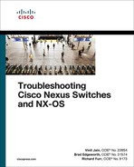
FabricPath-based design allows hosts to leverage the benefit of multiple active Layer 3 default gateways, as Figure 5-9 shows. The hosts see a single default gateway. The fabric provides forwarding toward the active default gateways transparently and simultaneously, thus extending the multipathing from inside the fabric to the Layer 3 domain outside the fabric.
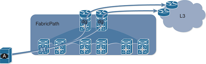
Figure 5-9 Access to Multiple Active Default Gateways
The fabric also is used to extend Layer 3 networks. An arbitrary number of routed interfaces can be created at the edge or within the fabric. The attached Layer 3 devices peer with those interfaces, thus providing a seamless Layer 3 network integration.
FabricPath Terminologies and Components
Before understanding the packet flow within the FabricPath (FP)–enabled network, it is important to understand the various terminologies and components that collectively form the FabricPath architecture. Figure 5-10 examines a standard FabricPath-enabled spine-leaf topology, also known as the Clos fabric. The leaf or edge switches in the topology have two different interfaces:
FabricPath (FP) core ports
Classical Ethernet (CE) edge ports

Figure 5-10 FabricPath and Clos Fabric
The FP core ports provide connectivity to the spine and are FabricPath-enabled interfaces. The FP core network is used to perform the following functions:
Send and receive FP frames
Avoid STP, require no MAC learning, and require no MAC address table maintained by FP Core ports
Decide the best path by using a routing table computed by IS-IS
The CE edge ports are regular trunk or access ports that provide connectivity to the hosts or other classical switches. The CE ports perform the following functions:
Send and receive regular Ethernet frames
Run STP, perform MAC address learning, and maintain a MAC address table
The FP edge device maintains the association of MAC addresses and switch-IDs (which IS-IS automatically assigns to all switches). FP also introduces a new data plane encapsulation by adding a 16-byte FP frame on top of the classical Ethernet header. Figure 5-11 displays the FP encapsulation header, which is also called the MAC-in-MAC header. The external FP header consists of Outer Destination Address, Outer Source Address, and FP tag. Important fields of the Outer Source or Destination address fields within the FP header include the following:
Switch-ID (SID): Identifies each FP switch by a unique number
Sub-Switch ID (sSID): Identifies devices and hosts connected via vPC+
Local ID (LID): Identifies the exact port that sourced the frame or to which the frame is destined. The egress FP switch uses LID to determine the output interface, thus removing the requirement for MAC learning on FP core ports. LID is locally significant.
Figure 5-11 FabricPath Packet Structure
The FP tag primarily has three fields:
Etype: The Ethernet type is set to 0x8903.
Ftag: This is the forwarding tag, a unique 10-bit number identifying the topology and/or distribution tree. For unicast packets, the Ftag identifies which FP IS-IS topology to use. For multidestination packets (broadcast, unknown unicast, and multicast packets), the Ftag identifies which distribution tree to use. FTAG 1 is used for broadcast, unknown unicast, and multicast (BUM) traffic; FTAG 2 is used for multicast. FTAG is a 10-bit field, allowing support for 1024 forwarding trees or topologies.
TTL: The TTL is decremented at each switch hop, to prevent frames from looping infinitely.
Note
If more than 1024 topologies are required, the FTAG value is set to 0 and the VLAN is used to identify the topology for multidestination trees.
FabricPath Packet Flow
To understand packet forwarding in a FabricPath domain, examine the topology and steps shown in Figure 5-12. This figure has four spine switches (S10, S20, S30, and S40) and three leaf/edge switches (S100, S200, and S300). Each leaf switch has connectivity to each of the four spine switches. Host A with MAC address A is connected to CE port on S100, and Host B with MAC address B is connected to CE port on S300.

Figure 5-12 Broadcast ARP Request Packet
When hosts A and B do not know about each other’s MAC addresses, the first packet is a broadcast ARP request. The following steps describe the packet flow for the broadcast frame from host A to host B:
Step 1. Host A sends an ARP request for host B. Because the ARP request is a broadcast packet, the source MAC is set to A and the destination MAC is set to FF (the broadcast address).
Step 2. When the packet reaches the CE edge port on leaf S100, the MAC address table of S100 is updated with MAC address A and the interface from which it is learned. In this case, it is Ethernet1/1.
Step 3. The leaf switch S100 then encapsulates the Ethernet frame with an FP header. Because the FP core ports are enabled, IS-IS has already precalculated multidestination trees on S100. Tree 1 represents the multidestination tree and indicates that the packet must be sent over the FP core ports (po10, po20, po30, and po40). Because this is a broadcast frame, the Ftag is set to 1. Note that the broadcast graph uses Tree ID 1 (Ftag 1) and the packet is forwarded to S10.
Step 4. When the FP encapsulated frame reaches S10, it honors the Ftag 1 and does a lookup for the Tree ID.
Step 5. In this case, the Tree ID 1 represents a multidestination tree pointing to FP core interface po100, po200, and po300 toward the S100, S200, and S300 leaf switches. Node S10 also performs a reverse path forwarding (RPF) check to validate the reception of the packet over the L2 interface and sends the packet over the multidestination FP encapsulated frame to S200 and S300.
Step 6. The egress FP switch (S300) receives the packet on link po10, performs an RPF check to validate the reception of the packet, and floods the packet to its CE ports.
Step 7. S300 then removes the FP header and floods the packet within the VLAN based on the broadcast frame. Note that the egress FP switch (S300, in this case) does not update its MAC address table with A. This is because the edge devices don’t learn the MAC address from flood frames received from the FP core where the destination MAC address is set to FF. The original broadcast packet is then sent to host B.
When the ARP request reaches host B, the ARP reply is a unicast packet. Figure 5-13 depicts the packet flow for ARP reply from host B to host A.

Figure 5-13 Unicast ARP Reply Packet
The following steps describe the packet flow for ARP reply from B to A across the fabric.
Step 1. Host B with MAC address B sends the ARP reply back to host A. In the ARP response, the source MAC is set to B and the destination MAC is set to A.
Step 2. When the packet reaches the leaf switch S300, it updates its MAC address table with MAC address B, but it still does not have information about MAC address A. This makes the packet an unknown unicast packet.
Step 3. S300, the ingress FP switch, determines which tree to use. Unknown unicast typically uses the first Tree ID (Ftag 1). The Tree ID 1 points to all the FP core interfaces on switch S300 (po10, po20, po30, and po40). The ingress FP switch also sets the outer destination MAC address to the well-known “flood to fabric” multicast address represented as MC1—01:0F:FF:C1:01:C0.
Step 4. The FP encapsulated unknown unicast packet is sent to all the spine switches. Other FP switches honor the Tree ID selected by the ingress switch (Tree 1, in this case). When the packet reaches the root for Tree 1 (S10), it uses the same Ftag 1 and forwards the packet out of interfaces po100 and po200. (It does not forward the packet on po300 because this is the interface from which the frame was received).
Step 5. When the packet reaches S100, it performs a lookup on the FP trees and uses Tree ID 1, which is set to po10. Because the packet from S10 was received on po10 on the S100 switch, the packet is not forwarded back again to the fabric.
Step 6. The FP header is then decapsulated and the ARP reply is forwarded to the host with MAC A. At this point, the MAC address table on S100 is updated with MAC address B, with the IF/SID pointing to S300. This is because the destination MAC is known inside the frame.
The next time host A sends a packet to host B, the packet from A is sent with source MAC A and destination MAC B. The switch S100 receives the packet on the CE port, and the destination MAC is already known and points to the switch S300 in an FP-enabled network. The FP routing table is looked up to find the shortest path to S300 using a flow-based hash because multiple paths to S300 exist. The packet is encapsulated with the FP header with a source switch-ID (SWID) of S100 and a destination SWID of S300, and the FTAG is set to 1. The packet is received on one of the spine switches. The spine switch then performs an FP routing lookup for S300 and sends the packet to an outgoing interface toward S300. When the packet reaches S300, the MAC address for A is updated in the MAC address table with the IF/SID pointing to S100.
FabricPath Configuration
To configure FabricPath and verify a FabricPath-enabled network, examine the topology shown in Figure 5-14. This figure has two spine nodes (NX-10 and NX-20) and three leaf nodes (NX-1, NX-2, and NX-3). The end host nodes, host A and host B, are connected to leaf nodes NX-1 and NX-3.

Figure 5-14 FabricPath-Enabled Topology
Enabling the FabricPath feature is a bit different than enabling other features. First the FabricPath feature set is installed, then the feature-set fabricpath is enabled, and then the FabricPath feature is enabled. Example 5-30 demonstrates the configuration for enabling FabricPath feature. FabricPath uses the Dynamic Resource Allocation Protocol (DRAP) for the allocation of switch-IDs. However, a switch-ID can be manually configured on a Nexus switch using the command fabricpath switch-id [1-4094]. Every switch in the FabricPath domain is required to be configured with the unique switch-ID.
Example 5-30 Enabling the FabricPath Feature
NX-1(config)# install feature-set fabricpath
NX-1(config)# feature-set fabricpath
NX-1(config)# fabricpath switch-id 1
When feature-set fabricpath is enabled, configure the FP VLANs. Two kinds of VLANs exist:
Classical Ethernet (CE) VLANs
FabricPath (FP) VLANs
FP VLANs are the VLANs that are carried over the FP-enabled links; CE VLANs are regular VLANs carried over the classical Ethernet links, such as trunk or access ports. To enable a VLAN as an FP VLAN, use the command mode fabricpath under VLAN configuration mode. When the FP VLAN is configured, configure the FP core links using the command switchport mode fabricpath. Finally, configure the CE link as a trunk or access port. Example 5-31 examines the configuration of FP VLAN, FP ports, and CE ports on NX-1 as shown in topology.
Example 5-31 Enabling FP Core Ports, FP VLAN, and CE Edge Ports
NX-1(config-vlan)# mode fabricpath
NX-1(config)# interface eth 6/1, eth6/5
NX-1(config-if-range)# switchport
NX-1(config-if-range)# switchport mode fabricpath
NX-1(config-if-range)# no shut
NX-1(config)# interface eth6/6
NX-1(config-if)# switchport
NX-1(config-if)# switchport access vlan 100
NX-1(config-if)# no shut
Various timers can also be configured with FabricPath, ranging from 1 to 1200 seconds:
allocate-delay: This timer is used when a new switch-ID is allocated and is required to be propagated throughout the network. The allocate-delay defines the delay before the new switch-ID is propagated and becomes available and permanent.
linkup-delay: This timer configures the delay before the link is brought up, to detect any conflicts in the switch-ID.
transition-delay: This command sets the delay for propagating the transitioned switch-ID value in the network. During this period, all old and new switch-ID values exist in the network.
Note
The default value of all these timers is 10 seconds.
FabricPath does not require a specific IS-IS configuration. Authentication and other IS-IS-related configuration settings (such as IS-IS hello timers, hello-padding, and metrics) can be configured using the command fabricpath isis under interface configuration mode.
Example 5-32 illustrates the configuration for enabling IS-IS MD5 authentication for FabricPath. The example also displays the various IS-IS settings defined under the interface. Ensure that the configuration matches on both ends of the interface.
Example 5-32 Enabling Authentication on FP Ports
NX-1(config-if)# fabricpath isis ?
authentication Set hello authentication keychain
authentication-check Check authentication on received hellos
authentication-type Set hello authentication type
csnp-interval Set CSNP interval in seconds
hello-interval Set Hello interval in seconds
hello-multiplier Set multiplier for Hello holding time
hello-padding Pad IS-IS hello PDUs to full MTU
lsp-interval Set LSP transmission interval
mesh-group Set IS-IS mesh group
metric Configure the metric for interface
mtu-check Check mtu on received hellos, if its padded
retransmit-interval Set per-LSP retransmission interval
retransmit-throttle-interval Set interface LSP retransmission interval
NX-1(config-if)# fabricpath isis authentication key-chain cisco
NX-1(config-if)# fabricpath isis authentication-type md5
NX-1(config-if)# exit
NX-1(config)# key chain cisco
NX-1(config-keychain)# key 1
NX-1(config-keychain-key)# key-string cisco
FabricPath Verification and Troubleshooting
When the fabric is enabled with FabricPath, verify the switch-IDs within the network. This is done using the command show fabricpath switch-id. This command displays all the learned switch-IDs within the fabric and their current state. If the switch-IDs are not statically assigned, the IS-IS process dynamically allocates them. Examine the output of the command show fabricpath switch-id to validate all the nodes in the fabric, as in Example 5-33.
Example 5-33 show fabricpath switch-id Command Output
FABRICPATH SWITCH-ID TABLE
Legend: '*' - this system
'[E]' - local Emulated Switch-id
'[A]' - local Anycast Switch-id
Total Switch-ids: 5
=============================================================================
SWITCH-ID SYSTEM-ID FLAGS STATE STATIC EMULATED/
ANYCAST
--------------+----------------+------------+-----------+--------------------
10 6c9c.ed4e.c141 Primary Confirmed Yes No
20 6c9c.ed4e.c143 Primary Confirmed Yes No
* 100 6c9c.ed4e.4b41 Primary Confirmed Yes No
200 6c9c.ed4e.4b42 Primary Confirmed Yes No
300 6c9c.ed4e.4b43 Primary Confirmed Yes No
In addition to verifying the FP switch-IDs, it is important to verify which interfaces are participating as part of the FP core links and which are CE-facing links. The FP core links on a leaf or spine node are easily identified using the command show fabricpath isis interface [brief]. The command output with the brief keyword displays brief information about core interfaces, such as the interfaces enabled with command switchport mode fabricpath, their state, the circuit-type (which is typically 0x1 or L1), MTU, Metric, Priority, Adjacency, and Adjacency Up state. More detailed information can be viewed using the same command without the brief keyword. The command show fabricpath isis interface displays information such as authentication (if enabled), adjacency information, and topology information, along with the information from the brief output. Example 5-34 displays both the brief and detailed information of FP core interfaces on leaf node NX-1.
Example 5-34 Verifying FP Core Interfaces
Fabricpath IS-IS domain: default
Interface Type Idx State Circuit MTU Metric Priority Adjs/AdjsUp
--------------------------------------------------------------------------------
Ethernet6/1 P2P 1 Up/Ready 0x01/L1 1500 40 64 1/1
Ethernet6/5 P2P 3 Up/Ready 0x01/L1 1500 40 64 1/1
NX-1# show fabricpath isis interface
Fabricpath IS-IS domain: default
Interface: Ethernet6/1
Status: protocol-up/link-up/admin-up
Index: 0x0001, Local Circuit ID: 0x01, Circuit Type: L1
Extended Local Circuit ID: 0x1A280000, P2P Circuit ID: 0000.0000.0000.00
Retx interval: 5, Retx throttle interval: 66 ms
LSP interval: 33 ms, MTU: 1500
P2P Adjs: 1, AdjsUp: 1, Priority 64
Hello Interval: 10, Multi: 3, Next IIH: 00:00:01
Level Adjs AdjsUp Metric CSNP Next CSNP Last LSP ID
1 1 1 40 60 Inactive ffff.ffff.ffff.ff-ff
Topologies enabled:
Level Topology Metric MetricConfig Forwarding
0 0 40 no UP
1 0 40 no UP
Interface: Ethernet6/5
Status: protocol-up/link-up/admin-up
Index: 0x0003, Local Circuit ID: 0x01, Circuit Type: L1
No authentication type/keychain configured
Authentication check specified
Extended Local Circuit ID: 0x1A284000, P2P Circuit ID: 0000.0000.0000.00
Retx interval: 5, Retx throttle interval: 66 ms
LSP interval: 33 ms, MTU: 1500
P2P Adjs: 1, AdjsUp: 1, Priority 64
Hello Interval: 10, Multi: 3, Next IIH: 00:00:03
Level Adjs AdjsUp Metric CSNP Next CSNP Last LSP ID
1 1 1 40 60 Inactive ffff.ffff.ffff.ff-ff
Topologies enabled:
Level Topology Metric MetricConfig Forwarding
0 0 40 no UP
1 0 40 no UP
The IS-IS adjacency between the leaf and the spine nodes is also verified using the command show fabricpath isis adjacency [detail]. Example 5-35 displays the adjacency on NX-1 and NX-10. The command displays the system ID, circuit type, interface participating in IS-IS adjacency for FabricPath, topology ID, and forwarding state. The command also displays the last time when the FabricPath transitioned to current state (that is, the last time the adjacency flapped).
Example 5-35 Verifying IS-IS Adjacency
Fabricpath IS-IS domain: default Fabricpath IS-IS adjacency database:
System ID SNPA Level State Hold Time Interface
NX-10 N/A 1 UP 00:00:29 Ethernet6/1
Up/Down transitions: 1, Last transition: 00:07:36 ago
Circuit Type: L1
Topo-id: 0, Forwarding-State: UP
NX-20 N/A 1 UP 00:00:22 Ethernet6/5
Up/Down transitions: 1, Last transition: 00:12:13 ago
Circuit Type: L1
Topo-id: 0, Forwarding-State: UP
Next, validate whether the necessary FabricPath VLANs are configured on the edge/leaf switches. This is verified by using the command show fabricpath isis vlan-range. When the FP VLANs are configured and CE-facing interfaces are configured, the edge devices learn about the MAC addresses of the hosts attached to the edge node. This is verified using the traditional command show mac address-table vlan vlan-id. Example 5-36 verifies the FP VLAN and the MAC addresses learned from the hosts connected to the FP VLAN 100.
Example 5-36 Verifying FabricPath VLANs and MAC Address Table
Fabricpath IS-IS domain: default
MT-0
Vlans configured:
100, 200, 300, 400, 500, 4040-4041
Note: MAC table entries displayed are getting read from software.
Use the 'hardware-age' keyword to get information related to 'Age'
Legend:
* - primary entry, G - Gateway MAC, (R) - Routed MAC, O - Overlay MAC
age - seconds since last seen,+ - primary entry using vPC Peer-Link,
(T) - True, (F) - False , ~~~ - use 'hardware-age' keyword to retrieve
age info
VLAN MAC Address Type age Secure NTFY Ports/SWID.SSID.LID
---------+-----------------+--------+---------+------+----+------------------
* 100 30e4.db97.e8bf dynamic ~~~ F F Eth6/6
100 30e4.db98.0e7f dynamic ~~~ F F 300.0.97
NX-3# show mac address-table vlan 100
Note: MAC table entries displayed are getting read from software.
Use the 'hardware-age' keyword to get information related to 'Age'
Legend:
* - primary entry, G - Gateway MAC, (R) - Routed MAC, O - Overlay MAC
age - seconds since last seen,+ - primary entry using vPC Peer-Link,
(T) - True, (F) - False , ~~~ - use 'hardware-age' keyword to retrieve
age info
VLAN MAC Address Type age Secure NTFY Ports/SWID.SSID.LID
---------+-----------------+--------+---------+------+----+------------------
100 30e4.db97.e8bf dynamic ~~~ F F 100.0.85
* 100 30e4.db98.0e7f dynamic ~~~ F F Eth6/18
Similar to Layer 3 IS-IS, Layer-2 IS-IS maintains multiple topologies within the network. Each topology is represented as a tree ID in the FabricPath domain. The trees are nothing but multidestination trees within the fabric. To view the IS-IS topologies in FabricPath domain, use the command show fabricpath isis topology [summary]. Example 5-37 displays the different IS-IS topologies in the present topology.
Example 5-37 FabricPath Topology Information
FabricPath IS-IS Topology Summary
Fabricpath IS-IS domain: default
MT-0
Configured interfaces: Ethernet6/1 Ethernet6/5
Max number of trees: 2 Number of trees supported: 2
Tree id: 1, ftag: 1, root system: 6c9c.ed4e.c143, 20
Tree id: 2, ftag: 2, root system: 6c9c.ed4e.c141, 10
Ftag Proxy Root: 6c9c.ed4e.c143
FabricPath IS-IS Topology
Fabricpath IS-IS domain: default
MT-0
Fabricpath IS-IS Graph 0 Level-1 for MT-0 IS routing table
NX-3.00, Instance 0x0000005C
*via NX-10, Ethernet6/1, metric 80
*via NX-20, Ethernet6/5, metric 80
NX-10.00, Instance 0x0000005C
*via NX-10, Ethernet6/1, metric 40
NX-20.00, Instance 0x0000005C
*via NX-20, Ethernet6/5, metric 40
If issues arise with traffic forwarding or MAC addresses not being learned, it is important to check whether the FP IS-IS adjacency has been established and whether the FP IS-IS routes are present in the Unicast Routing Information Base (URIB). This is easily validated through the command show fabricpath route [detail | switchid switch-id]. This command displays the routes for the remote nodes (leaf or spine nodes). The route is seen in the form of ftag/switch-id/subswitch-id. In Example 5-38, the route for remote edge device NX-3 is seen with FTAG 1, switch-ID 300, and Subswitch-ID 0 (because no vPC+ configuration was enabled).
Example 5-38 Verifying FabricPath Routes in URIB
FabricPath Unicast Route Table
'a/b/c' denotes ftag/switch-id/subswitch-id
'[x/y]' denotes [admin distance/metric]
FabricPath Unicast Route Table for Topology-Default
0/100/0, number of next-hops: 0
via ---- , [60/0], 0 day/s 00:16:18, local
1/10/0, number of next-hops: 1
via Eth6/1, [115/40], 0 day/s 00:16:01, isis_fabricpath-default
1/20/0, number of next-hops: 1
via Eth6/5, [115/40], 0 day/s 00:15:52, isis_fabricpath-default
1/200/0, number of next-hops: 2
via Eth6/1, [115/80], 0 day/s 00:16:01, isis_fabricpath-default
via Eth6/5, [115/80], 0 day/s 00:15:52, isis_fabricpath-default
1/300/0, number of next-hops: 2
via Eth6/1, [115/80], 0 day/s 00:09:14, isis_fabricpath-default
via Eth6/5, [115/80], 0 day/s 00:09:14, isis_fabricpath-default
FabricPath Unicast Route Table for Topology-Default
1/300/0, number of next-hops: 2
via Eth6/1, [115/80], 0 day/s 00:34:49, isis_fabricpath-default
via Eth6/7, [115/80], 0 day/s 00:34:49, isis_fabricpath-default
The previous output makes it clear that the route for NX-3 has an FTAG value of 1. When the route is verified in URIB, validate that the route is installed in the Forwarding Information Base (FIB). To verify the route present in the FIB, use the line card command show fabricpath unicast routes vdc vdc-number [ftag ftag] [switchid switch-id]. This command displays hardware route information along with its RPF interface in the software table on the line card. As part of the platform-dependent information, the command output returns the hardware table address, which is further used to verify the hardware forwarding information for the route. In the output shown in Example 5-39, the software table shows that the route is a remote route with the RPF interface of Ethernet6/5. It also returns the hardware table address of 0x18c0.
Example 5-39 Verifying Software Table in Hardware for FP Route
Attaching to module 6 ...
To exit type 'exit', to abort type '$.'
module-6# show fabricpath unicast routes vdc 1 ftag 1 switchid 300
--------------------------------------------------------------------------------
FTAG | SwitchID | SubSwitchID | Loc/Rem | RPF | RPF Intf | Num Paths | Merge V
--------------------------------------------------------------------------------
0001 | 0300 | 0000 | Remote | Yes | Eth6/5 | 2 | 1
--------------------------------------------------------------------------------
FE num | ADDR TYPE | HTBL ADDR | TCAM ADDR | SWSI
----------------------------------------------------------
0 | HASH TABLE | 000018c0 | 000000ff | 000011c1
1 | HASH TABLE | 000018c0 | 000000ff | 000011c1
--------------------------------------------------------------------------------
PD Information for ECMP:
Common Info
--------------------------------
AMM key : 0x24
--------------------------------
Next Hop | Interface | LID
--------------------------------
0 | Eth6/1 | 00000050
1 | Eth6/5 | 00000054
--------------------------------
Per FE Info
--------------------------------
FE num | MP_base | ref_count
--------------------------------
0 | 00000024 | 1
1 | 00000024 | 1
--------------------------------------------------------------------------------
Note
The commands in Example 5-39 are relevant for F2 and F3 line card modules on Nexus 7000/7700 series switches. The verification commands vary among line cards and also platforms (for instance, Nexus 5500).
Using the hardware address in the software table, execute the command show hardware internal forwarding instance instance-id table sw start hw-entry-addr end hw-entry-addr. The instance-id value is achieved from the FE num field in the previous example. The hw-entry-addr address is the address highlighted in the previous example output. This command output displays the switch-ID (swid), the Subswitch-ID (sswid), and various other fields. One of the important fields to note is ssw_ctrl. If the ssw_ctrl field is 0x0 or 0x3, the switch does not have subswitch-IDs (available only in the case of vPC+). If vPC+ configuration is available, the value is usually 0x1. Another field to look at is the local field. If the local field is set to n, multipath is available for the route, so a multipath table is required for verification. Example 5-40 demonstrates this command.
Example 5-40 Verifying FabricPath Routes in URIB
-----------------------------------------------------------
------------------------ SW Table ------------------------
(INST# 0)
-----------------------------------------------------------
[18c0]| KEY
[18c0]| vdc : 0 sswid : 0
[18c0]| swid : 12c ftag : 1
[18c0]| DATA
[18c0]| valid : y mp_mod : 1
[18c0]| mp_base : 24 local : n
[18c0]| cp_to_sup1 : n cp_to_sup2 : n
[18c0]| drop : n dc3_si : 11c1
[18c0]| data_tbl_ptr : 0 ssw_ctrl : 0
[18c0]| iic_port_idx : 54
[18c0]| l2tunnel_remote (CR only) : 0
Duplicate switch-IDs can cause forwarding issues and instability in the FabricPath-enabled network. To check whether the network has duplicate or conflicting switch-IDs, use the command show fabricpath conflict all. In case of any FabricPath-related errors, event-history logs for a particular switch-ID can be verified using the command show system internal fabricpath switch-id event-history errors. Alternatively, the show tech-support fabricpath command output can be collected for further investigation.
Note
If an issue arises with FabricPath, collect the following show tech-support outputs during the problematic state:
show tech u2rib
show tech pixm
show tech eltm
show tech l2fm
show tech fabricpath isis
show tech fabricpath topology
show tech fabricpath switch-id
Along with these show tech outputs, show tech details are useful in investigating issues in the FabricPath environment.
FabricPath Devices
FabricPath is supported on Nexus 7000/7700 and Nexus 5500 series switches. Check the FabricPath Configuration Guide for scalability and supported switch modules.
Emulated Switch and vPC+
In modern data center design, servers are usually connected to multiple edge devices to provide redundancy. In a FabricPath-enabled network, only the edge switches learn the L2 MAC addresses. The learning consists of mapping the MAC address to a switch-ID, which is a one-to-one association performed in a data plane. This association or mapping detects a MAC move when the host changes its location to another switch. A vPC allows links that are physically connected to two different Nexus switches to appear as single port-channel to a server or another switch. This provides a loop-free topology, eliminates the spanning tree blocked ports, and maximizes bandwidth usage.
In a FabricPath-enabled network, it is paramount to support the same configuration, with a host or Ethernet switch connected through a port-channel to two FabricPath edge switches. A dual-connected host can send a packet into the FabricPath network from both edge switches, leading to a MAC flap. Figure 5-15 illustrates the MAC flap caused by a dual-connected host. Host A is dual-connected to both edge switches S1 and S2 and is communicating with host B. When the frames are sent from switch S1, MAC-A is associated with switch S1; when frames are sent from S2, MAC-A is associated with switch S2. This results in a MAC flap. To address the problem, FabricPath implements the emulated switch.

Figure 5-15 FabricPath Topology with Dual-Connected Host
An emulated switch construct enables two or more FabricPath switches to work as a single switch to the rest of the FabricPath network. An emulated switch-ID is assigned to the emulated switch used to map the source MAC address when the packet leaves any FabricPath switch that emulates the single switch. The emulated switch implementations in FabricPath in which two FabricPath edge switches provide a vPC to a third device are called vPC+. The two emulating switches thus must be directly connected via peer link, and a peer keepalive path should exist between the two switches.
With emulating switches, it is also important to understand the forwarding mechanism for multidestination packets. In a FabricPath network, eliminating duplication of multidestination frames is achieved by computing multidestination trees rooted at shared nodes that guarantee a loop-free path to any switch. This implies that only one of the emulating switches should announce connectivity to the emulated switch for a particular multidestination tree and should be responsible for forwarding packets to the emulated switch. Likewise, traffic from the emulated switch can ingress from one of the emulating switches into the FabricPath network along the graph path that has reachability to the emulating switch. Otherwise, the packet will be dropped by ingress interface check (IIC). For this reason, for each multidestination tree, one emulating switch is used for ingress and egress traffic.
vPC+ Configuration
To configure vPC+, two primary features must be enabled on the Nexus switch:
FabricPath
vPC
To understand how the vPC+ feature works, examine the topology in Figure 5-16. In this topology, NX-1 and NX-2 are forming a vPC with SW-12, and NX-3 and NX-4 are forming a vPC with SW-34. All the links among the four Nexus switches are FabricPath-enabled links, including the vPC peer link.

Figure 5-16 vPC+ Topology
Examine the vPC and FabricPath configuration for NX-1 and NX-3 in Example 5-41. Most of the configuration is similar to the configuration shown in the section on vPC and FabricPath. The main differentiating configuration is the fabricpath switch-id switch-id command configured under vPC configuration mode. The same switch-ID values are assigned on both the emulated switches NX-1 and NX-2 (assigned the switch-ID of 100) and NX-3 and NX-4 (assigned the switch-ID of 200).
Example 5-41 vPC+ Configuration on NX-1 and NX-3
install feature-set fabricpath
feature-set fabricpath
feature vpc
vlan 100,200,300,400,500
mode fabricpath
!
vpc domain 10
peer-keepalive destination 10.12.1.2 source 10.12.1.1 vrf default
fabricpath switch-id 100
!
interface port-channel1
switchport mode fabricpath
vpc peer-link
!
interface Ethernet6/4
switchport mode fabricpath
!
interface Ethernet6/5
switchport mode fabricpath
!
interface port-channel10
switchport
switchport mode trunk
vpc 10
install feature-set fabricpath
feature-set fabricpath
feature vpc
vlan 100,200,300,400,500
mode fabricpath
!
vpc domain 20
peer-keepalive destination 10.34.1.4 source 10.34.1.3 vrf default
fabricpath switch-id 200
!
interface port-channel1
switchport mode fabricpath
vpc peer-link
!
interface Ethernet6/16
switchport mode fabricpath
!
interface Ethernet6/17
switchport mode fabricpath
!
interface port-channel20
switchport
switchport mode trunk
vpc 20
vPC+ Verification and Troubleshooting
When the FabricPath and vPC configuration is complete, verify that the vPC peer adjacency is established. When vPC+ is configured, the command show vpc not only displays the vPC-related information: It also shows the vPC+ switch-ID, which is the emulated switch-ID; the DF Flag, which indicates whether the switch is acting as a Designated Forwarder (DF); and the FP MAC route, which is assigned by the vPC Manager. Example 5-42 displays the show vpc command output highlighting these fields.
Example 5-42 show vpc Command Output
Legend:
(*) - local vPC is down, forwarding via vPC peer-link
vPC domain id : 10
vPC+ switch id : 100 Peer status : peer adjacency formed ok
vPC keep-alive status : peer is alive
vPC fabricpath status : peer is reachable through fabricpath
Configuration consistency status : success
Per-vlan consistency status : success
Type-2 consistency status : success
vPC role : primary
Number of vPCs configured : 1
Peer Gateway : Disabled
Dual-active excluded VLANs and BDs : -
Graceful Consistency Check : Enabled
Auto-recovery status : Enabled (timeout = 240 seconds)
Fabricpath load balancing : Disabled
Operational Layer3 Peer-router : Disabled
Port Channel Limit : limit to 244
Self-isolation : Disabled
vPC Peer-link status
--------------------------------------------------------------------------------
id Port Status Active vlans Active BDs
-- ---- ------ -------------------------------------------------------------
1 Po1 up 100,200,300,400,500 -
vPC status
Id : 10
Port : Po10
Status : up
Consistency : success
Reason : success
Active Vlans : 100,200,300,400,500
VPC+ Attributes: DF: Yes, FP MAC: 100.11.65535
When verifying the emulated FabricPath switch-IDs, the command show fabricpath switch-id displays not only the static switch-IDs, but also the emulated switch-IDs. The Flag (E) is set beside the node representing the local emulated switch. Example 5-43 displays the emulated switch-IDs using the show fabricpath switch-id command.
Example 5-43 Verifying Emulated Switch-IDs
FABRICPATH SWITCH-ID TABLE
Legend: '*' - this system
'[E]' - local Emulated Switch-id
'[A]' - local Anycast Switch-id
Total Switch-ids: 8
=============================================================================
SWITCH-ID SYSTEM-ID FLAGS STATE STATIC EMULATED/
ANYCAST
--------------+----------------+------------+-----------+--------------------
* 10 6c9c.ed4f.28c2 Primary Confirmed Yes No
20 d867.d97f.fc42 Primary Confirmed Yes No
30 6c9c.ed4f.28c3 Primary Confirmed Yes No
40 d867.d97f.fc43 Primary Confirmed Yes No
[E] 100 6c9c.ed4f.28c2 Primary Confirmed No Yes
100 d867.d97f.fc42 Primary Confirmed No Yes
200 6c9c.ed4f.28c3 Primary Confirmed No Yes
200 d867.d97f.fc43 Primary Confirmed No Yes
When both edge devices running the emulated switch learn the MAC addresses from the remote edge nodes, the address for the interfaces is shown with the MAC route assigned on the vPC interface of the remote edge node. Example 5-44 displays the MAC address table on both NX-1 and NX-3 nodes. Notice that the MAC address for the remote host connected on the NX-3/NX-4 vPC link is learned with the interface assigned with FP MAC route 200.11.65535 on NX-1. For the host connected to NX-1 and NX-2, the vPC link is learned with the interface assigned with FP MAC route 100.11.65535.
Example 5-44 MAC Address Table
Note: MAC table entries displayed are getting read from software.
Use the 'hardware-age' keyword to get information related to 'Age'
Legend:
* - primary entry, G - Gateway MAC, (R) - Routed MAC, O - Overlay MAC
age - seconds since last seen,+ - primary entry using vPC Peer-Link, E -
EVPN entry
(T) - True, (F) - False , ~~~ - use 'hardware-age' keyword to retrieve
age info
VLAN/BD MAC Address Type age Secure NTFY Ports/SWID.SSID.LID
---------+-----------------+--------+---------+------+----+------------------
100 0022.56b9.007f dynamic ~~~ F F 200.11.65535
* 100 24e9.b3b1.8cff dynamic ~~~ F F Po10
Note: MAC table entries displayed are getting read from software.
Use the 'hardware-age' keyword to get information related to 'Age'
Legend:
* - primary entry, G - Gateway MAC, (R) - Routed MAC, O - Overlay MAC
age - seconds since last seen,+ - primary entry using vPC Peer-Link, E -
EVPN entry
(T) - True, (F) - False , ~~~ - use 'hardware-age' keyword to retrieve
age info
VLAN/BD MAC Address Type age Secure NTFY Ports/SWID.SSID.LID
---------+-----------------+--------+---------+------+----+------------------
* 100 0022.56b9.007f dynamic ~~~ F F Po20
100 24e9.b3b1.8cff dynamic ~~~ F F 100.11.65535
If issues arise with MAC learning, check that an IS-IS adjacency exists between the devices. The IS-IS adjacency is established with the vPC peer device and the other spines or edge nodes based on their connectivity. After verifying the adjacency, the FP routes are learned through IS-IS. The route for the emulated switch from the vPC peer is learned through the vPC Manager (vPCM) and is seen in the URIB as learned through vpcm, as Example 5-45 shows. Looking deeper into the URIB, notice that the route learned from remote emulated switch has the Flag or Attribute set to E.
Example 5-45 Verifying Local and Remote FP Routes in URIB
FabricPath Unicast Route Table
'a/b/c' denotes ftag/switch-id/subswitch-id
'[x/y]' denotes [admin distance/metric]
ftag 0 is local ftag
subswitch-id 0 is default subswitch-id
FabricPath Unicast Route Table for Topology-Default
0/10/0, number of next-hops: 0
via ---- , [60/0], 0 day/s 02:16:33, local
0/10/3, number of next-hops: 1
via sup-eth1, [81/0], 0 day/s 02:16:33, fpoam
0/100/1, number of next-hops: 0
0/100/3, number of next-hops: 1
via sup-eth1, [81/0], 0 day/s 01:54:49, fpoam
0/100/11, number of next-hops: 1
via Po10, [80/0], 0 day/s 01:47:44, vpcm
1/20/0, number of next-hops: 1
via Po1, [115/20], 0 day/s 01:33:20, isis_fabricpath-default
1/30/0, number of next-hops: 1
via Eth6/4, [115/40], 0 day/s 02:13:59, isis_fabricpath-default
1/40/0, number of next-hops: 1
via Eth6/5, [115/40], 0 day/s 02:13:14, isis_fabricpath-default
1/100/0, number of next-hops: 0
via ---- , [60/0], 0 day/s 01:54:49, local
1/100/0, number of next-hops: 1
via Po1, [115/20], 0 day 00:00:00, isis_fabricpath-default
1/200/0, number of next-hops: 2
via Eth6/4, [115/40], 0 day/s 01:41:01, isis_fabricpath-default
via Eth6/5, [115/40], 0 day/s 01:41:01, isis_fabricpath-default
2/100/0, number of next-hops: 0
via ---- , [60/0], 0 day/s 01:54:49, local
Fabricpath IS-IS domain: default MT-0
Topology 0, Tree 0, Swid routing table
20, L1
Attribute:P* Instance 0x0000002B
via port-channel1, metric 20*
Attribute:E* Instance 0x0000002B
via port-channel1, metric 20*
200, L1
Attribute:E* Instance 0x0000002B
via Ethernet6/4, metric 40*
via Ethernet6/5, metric 40*
Legend E:Emulated, A:Anycast P:Physical, * - directly connected
The edge ports are usually vPC ports in a vPC+-based design, so verifying the vPCM information related to the vPC link is vital. This is verified using the command show system internal vpcm info interface interface-id. This command displays the outer FP MAC address of the port-channel interface, VLANs, vPC peer information, and also the information stored in the PSS. Note that the PSS information helps ensure restoration of the information in case of any link flaps or VDC/switch reloads. Example 5-46 displays the vPCM information for port-channel 10 on NX-1 node, highlighting the FP MAC addresses and the information from vPC peers.
Example 5-46 Verifying FP MAC Information in vPCM
--------------------------------------------------------------------------------
IF Elem Information:
IF Index: 0x16000009
MCEC NUM: 10 Is MCEC
Allowed/Config VLANs : 6 - [1,100,200,300,400,500]
Allowed/Config BDs : 0 - []
vPC number : 10
Num members : 0
vPC state : Up
Internal vPC state: Up
Compat Status :
Old Compat Status : Pass
Current Compat Status: Pass
Reason Code : SUCCESS
Param compat reason code:0(SUCCESS)
Individual mode: N
Flags : 0x0
Is AutoCfg Enabled : N
Is AutoCfg Sync Complete : N
Number of members: 0
FEX Parameters:
vPC is a non internal-vpc
vPC is a non fabric-vpc
FPC bringup: FALSE
Parent vPC number: 0
Card type : F2
Hardware prog state : No R2 prog
Assoc flag: Disassociated
Is switchport: Yes Is shared port: FALSE
Up VLANs : 5 - [100,200,300,400,500]
Suspended VLANs : 1 - [1]
Compat check pass VLANs: 4096 - [0-4095]
Compat check fail VLANs: 0 - []
Up BDs : 0 - []
Suspended BDs : 0 - []
Compat check pass BDs : 0 - []
Compat check fail BDs : 0 - []
Compat check pass VNIs : 0 - []
Compat check fail VNIs : 0 - []
Peer Number : 10
Peer IF Index: 0x16000009
Peer state : Up
Card type : F2
Peer Up VLANs : 5 - [100,200,300,400,500]
Peer configured VNIs : 0 - []
Peer Up BDs : 0 - []
IF Index : 0x16000009
vPC number: 10
vPC state: Up
Internal vPC state: Up
Old Compat Status: Pass
Compat Status: Pass
Card type : F2
Fabricpath outer MAC address info: 100.11.65535
Designated forwarder state: Allow
Up VLANs : 5 - [100,200,300,400,500]
Suspended VLANs : 1 - [1]
Up BDs : 0 - []
Suspended BDs : 0 - []
vPC Peer Information:
Peer number: 10
Peer if_index: 0x16000009
Peer state: Up
Card type : F2
Peer Up VLANs : 5 - [100,200,300,400,500]
Other platform-level verification is done as shown in the FabricPath section to validate the hardware programming on the line card for the FabricPath route.
Note
The platform-dependent commands vary among platforms and also depend on the line card present on the Nexus 7000/7700 chassis. If you encounter any issues with vPC+, collect the following show tech-support command outputs:
show tech-support fabricpath
show tech-support vpc
Other show tech-support commands are collected as covered in the FabricPath section.
Summary
This chapter covered the technologies and features that provide resiliency and increased capacity between switches from an L2 forwarding perspective. Port-channels and virtual port-channels enable switches to create a logical interface with physical member ports. Consistency in port configuration for all member ports is the most common problem when troubleshooting these issues. This chapter detailed additional techniques and error messages to look for when troubleshooting these issues.
FabricPath provides a different approach for removing spanning tree while increasing link throughput and scalability and minimizing broadcast issues related to spanning tree. Quite simply, FabricPath involves routing packets in an L2 realm in an encapsulated state; the packet is later decapsulated before being forwarded to a host. Troubleshooting packet forwarding in a FabricPath topology uses some of the basic concepts from troubleshooting STP and port forwarding while combining them with concepts involved in troubleshooting an IS-IS network.
References
Fuller, Ron, David Jansen, and Matthew McPherson, Matthew. NX-OS and Cisco Nexus Switching (Indianapolis: Cisco Press, 2013).
Cisco NX-OS Software Configuration Guides. http://www.cisco.com.