Chapter 14
Troubleshooting Overlay Transport Virtualization (OTV)
This chapter covers the following topics:
Overlay Transport Virtualization (OTV) is a MAC-in-IP overlay encapsulation that allows Layer 2 (L2) communication between sites that are separated by a Layer 3 (L3) routed network. OTV revolutionized network connectivity by extending L2 applications across multiple data centers without changing the existing network design. This chapter focuses on providing an overview of OTV, the processes for the OTV control and data plane and how to troubleshoot OTV.
OTV Fundamentals
The desire to connect data center sites at L2 is driven by the need for Virtual Machine (VM) and workload mobility, or for creating geographically diverse redundancy. Critical networks may even choose to have a fully mirrored disaster recovery site that synchronizes data and services between sites. Having the capability to put services from multiple locations into the same VLAN allows mobility between data centers without reconfiguring the network layer addressing of the host or server when it is moved. The challenges and considerations associated with connecting two or more data centers at L2 are the following:
Transport network types available
Multihoming sites for redundancy
Allowing each site to be independent from the others
Creating fault isolation boundaries
Ensuring the network can be expanded to future locations without disruption to existing sites
Before OTV, L2 data center interconnect (DCI) was achieved with the use of direct fiber links configured as L2 trunks, IEEE 802.1Q Tunneling (Q-in-Q), Ethernet over MPLS (EoMPLS), or Virtual Private LAN Service (VPLS). These options rely on potentially complex configuration by a transport service provider to become operational. Adding a site with those solutions means the service provider needs to be involved to complete the necessary provisioning.
OTV, however, can provide an L2 overlay network between sites using only an L3 routed underlay. Because OTV is encapsulated inside an IP packet for transport, it can take advantage of the strengths of L3 routing; for example, IP Equal Cost Multipath (ECMP) routing for load sharing and redundancy as well as optimal packet paths between OTV edge devices (ED) based on routing protocol metrics. Troubleshooting is simplified as well because traffic in the transport network is traditional IP with established and familiar troubleshooting techniques.
Solutions for L2 DCI such as Q-in-Q, EoMPLS, and VPLS all require the service provider to perform some form of encapsulation and decapsulation on the traffic for a site. With OTV, the overlay encapsulation boundary is moved from the service provider to the OTV site, which provides greater visibility and control for the network operator. The overlay configuration can be modified at will and does not require any interaction with or dependence on the underlay service provider. Modifications to the overlay include actions like adding new OTV sites or changing which VLANs are extended across the OTV overlay.
The previously mentioned transport protocols rely on static or stateful tunneling. With OTV, encapsulation of the overlay traffic happens dynamically based on MAC address to IP next-hop information supplied by OTV’s Intermediate System to Intermediate System (IS-IS) control plane. This concept is referred to as MAC address routing, and it is explored in detail throughout this chapter. The important point to understand is that OTV maps a MAC address to a remote IP next-hop dynamically using a control plane protocol.
Multihoming is desirable for redundancy purposes, but could be inefficient if those redundant links and devices never get used. With traditional L2 switching, multihoming had to be planned and configured carefully to avoid L2 loops and Spanning-Tree Protocol (STP) blocking ports. OTV has considerations for multihoming built in to the protocol. For example, multiple OTV edge devices can be deployed in a single site, and each can actively forward traffic for different VLANs. Between data centers, multiple L3 routed links exist and provide L3 ECMP redundancy and load sharing between the OTV edge devices in each data center site.
Having redundant data centers is useful only if they exist in different fault domains, and problems from one data center do not affect the other. This implies that each data center must be isolated in terms of STP, and traffic forwarding loops between sites must be avoided. OTV allows each data center site to contain an independent STP Root Bridge for the VLANs extended across OTV. This is possible because OTV does not forward STP Bridge Protocol Data Units (BPDU) across the overlay, allowing each site to function independently.
Flood Control and Broadcast Optimization
Traditional L2 switches learn MAC addresses when frames arrive on a port. The source MAC address and associated interface mapping are kept until the MAC address is aged out or learned on a new interface. If the destination MAC address is not yet known, a switch performs unicast flooding. When this occurs, the unknown unicast traffic is flooded on all ports of the VLAN in an effort to reach the correct destination. In contrast, OTV learns MAC addresses from the remote data center through the IS-IS control plane protocol and will not flood any unknown unicast traffic across the overlay. Address Resolution Protocol (ARP) traffic is another source of flooded traffic in traditional switched networks. With OTV enabled, ARP is flooded in a controlled manner, and ARP responses are snooped and stored in a local ARP Neighbor Discovery (ND) cache by the OTV edge device. Any subsequent ARP requests for the host are answered by the OTV edge device on behalf of the host, which reduces the amount of broadcast traffic crossing the overlay.
Broadcast and multicast traffic in a VLAN must reach all remote data center locations. OTV relies on IP multicast in the underlay transport network to deliver this type of traffic in an efficient and scalable manner. By utilizing IP multicast transport, OTV eliminates the need for an edge device to perform head-end replication for each remote edge device. Head-end replication means that the originating OTV edge device creates a copy of the frame for each remote edge device. This can become a burden if there are many OTV sites and the packet rate is high. By using IP multicast transport, the OTV edge device needs to create only a single packet. Replication happens automatically by the multicast-enabled routers in the underlay transport network as the packets traverse the multicast tree to the receivers (Remote OTV edge devices).
Supported OTV Platforms
OTV is supported on the Nexus 7000 series and requires the Transport Service license (TRS) to be installed. Most deployments take advantage of Virtual Device Contexts (VDC) to logically separate the routing and OTV responsibilities in a single chassis.
Note
OTV is also supported on Cisco ASR1000 series routers. The protocol functionality is similar but there may be implementation differences. This chapter focuses only on OTV on the Nexus 7000 series switches.
VLANs are aggregated into a distribution switch and then fed into a dedicated OTV VDC through a L2 trunk. Any traffic in a VLAN that needs to reach the remote data center is switched to the OTV VDC where it gets encapsulated by the edge device. The packet then traverses the routed VDC as an L3 IP packet and gets routed toward the remote OTV edge device for decapsulation. Traffic that requires L3 routing is fed from the L2 distribution to a routing VDC. The routing VDC typically has a First Hop Redundancy Protocol (FHRP) like Hot Standby Router Protocol (HSRP) or Virtual Router Redundancy Protocol (VRRP) to provide a default-gateway address to the hosts in the attached VLANs and to perform Inter VLAN routing.
Note
Configuring multiple VDCs may require the installation of additional licenses, depending on the requirements of the deployment and the number of VDCs.
OTV Terminology
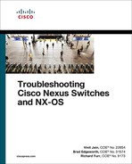
An OTV network topology example is shown in Figure 14-1. There are two data center sites connected by an L3 routed network that is enabled for IP multicast. The L3 routed network must provide IP connectivity between the OTV edge devices for OTV to function correctly. The placement of the ED is flexible as long as the OTV ED receives L2 frames for the VLANs that require extension across OTV. Usually the OTV ED is connected at the L2 and L3 boundary.
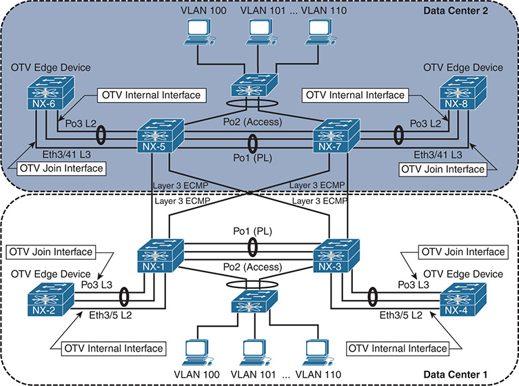
Figure 14-1 OTV Topology Example
Data center 1 contains redundant OTV VDCs NX-2 and NX-4, which are the edge devices. NX-1 and NX-3 perform the routing and L2 VLAN aggregation and connect the access switch to the OTV VDC internal interface. The OTV join interface is a Layer 3 interface connected to the routing VDC. Data center 2 is configured as a mirror of Data center 1; however, the port-channel 3 interface is used as the OTV internal interface instead of the OTV join interface as in Data center 1. VLANs 100–110 are being extended with OTV between the data centers across the overlay.
The OTV terminology introduced in Figure 14-1 is explained in Table 14-1.
Term |
Definition |
Edge Device (ED) |
Responsible for dynamically encapsulating Ethernet frames into L3 IP packets for VLANs that are extended with OTV. |
Authoritative Edge Device (AED) |
Forwards traffic for an extended VLAN across OTV. Advertises MAC-address reachability for the VLANs it is active for to remote sites through the OTV IS-IS control plane. The Authoritative Edge Device (AED) is determined based on an ordinal value of 0 (zero) or 1 (one). The edge device with ordinal zero is AED for all even VLANs, and the edge device with ordinal one is AED for all odd VLANs. This ordinal is determined when the adjacency is formed between two edge devices at a site and is not configurable. |
Internal Interface |
Interface on the OTV edge device that connects to the local site. This interface provides a traditional L2 interface from the ED to the internal network, and MAC addresses are learned as traffic is received. The internal interface is an L2 trunk that carries the VLANs being extended by OTV. |
Join Interface |
Interface on the OTV edge device that connects to the L3 routed network and used to source OTV encapsulated traffic. It can be a Loopback, L3 point-to-point interface, or L3 Port-channel interface. Subinterfaces may also be used. Multiple overlays can use the same join interface. |
Overlay Interface |
Interface on the OTV ED. The overlay interface is used to dynamically encapsulate the L2 traffic for an extended VLAN in an IP packet for transport to a remote OTV site. Multiple overlay interfaces are supported on an edge device. |
Site VLAN |
A VLAN that exists in the local site that connects the OTV edge devices at L2. The site VLAN is used to discover other edge devices in the local site and allows them to form an adjacency. After the adjacency is formed, the Authoritative Edge Device (AED) for each VLAN is elected. The site VLAN should be dedicated for OTV and not extended across the overlay. The site VLAN should be the same VLAN number at all OTV sites. |
Site Identifier |
The site-id must be the same for all edge devices that are part of the same site. Value ranges from 0x1 to 0xffffffff. The site-id is advertised in IS-IS packets, and it allows edge devices to identify which edge devices belong to the same site. Edge devices form an adjacency on the overlay as well as on the site VLAN (Dual adjacency). This allows the adjacency between edge devices in a site to be maintained even if the site VLAN adjacency gets broken due to a connectivity problem. The overlay interface will not come up until a site identifier is configured. |
Site Adjacency |
Formed across the site VLAN between OTV edge devices that are part of the same site. If an IS-IS Hello is received from an OTV ED on the site VLAN with a different site-id than the local router, the overlay is disabled. This is done to prevent a loop between the OTV internal interface and the overlay. This behavior is why it is recommended to make the OTV internal VLAN the same at each site. |
Overlay Adjacency |
OTV adjacency established on the OTV join interface. Adjacencies on the overlay interface are formed between sites, as well as for edge devices that are part of the same site. Edge devices form dual adjacency (site and overlay) for resiliency purposes. For devices in the same site to form an overlay adjacency, the site-id must match. |
Deploying OTV
The configuration of the OTV edge device consists of the OTV internal interface, the join interface, and the overlay virtual interface. Before attempting to configure OTV, the capabilities of the transport network must be understood, and it must be correctly configured to support the OTV deployment model.
OTV Deployment Models
There are two OTV deployment models available, depending on the capabilities of the transport network.
Multicast Enabled Transport: The control plane is encapsulated in IP multicast packets. Allows for dynamic neighbor discovery by having each OTV ED join the multicast control-group through the transport. A single multicast packet is sent by the OTV ED, which gets replicated along the multicast tree in the transport to each remote OTV ED.
Adjacency Server Mode: Neighbors must be manually configured for the overlay interface. Unicast control plane packets are created for each individual neighbor and routed through the transport.
The OTV deployment model that is deployed should be decided during the planning phase after verifying the capabilities of the transport network. If multicast is supported in the transport, it is recommended to use the multicast deployment model. If there is no multicast support available in the transport network, use the adjacency server model.
The transport network must provide IP routed connectivity for unicast and multicast communication between the OTV EDs. The unicast connectivity requirements are achieved with any L3 routing protocol. If the OTV ED does not form a dynamic routing adjacency with the data center, it must be configured with static routes to reach the join interfaces of the other OTV EDs.
Multicast routing in the transport must be configured to support Protocol Independent Multicast (PIM). An Any Source Multicast (ASM) group is used for the OTV control-group, and a range of PIM Source Specific Multicast (SSM) groups are used for OTV data-groups. IGMPv3 should be enabled on the join interface of the OTV ED.
Note
It is recommended to deploy PIM Rendezvous Point (RP) redundancy in the transport network for resiliency.
OTV Site VLAN
Each OTV site should be configured with an OTV site VLAN. The site VLAN should be trunked from the data center L2 switched network to the OTV internal interface of each OTV ED. Although not required, it is recommended to use the same VLAN at each OTV site in case the site VLAN is accidentally leaked between OTV sites.
With the deployment model determined and the OTV VDC created with the TRANSPORT_SERVICES_PKG license installed, the following steps are used to enable OTV functionality. The following examples are based upon a multicast enabled transport.
OTV Configuration
Before any OTV configuration is entered, the feature must be enabled with the feature otv command. Example 14-1 shows the configuration associated with the OTV internal interface, which is the L2 trunk port that participates in traditional switching with the existing data center network. The VLANs to be extended over OTV are VLAN 100–110. The site VLAN for both data centers is VLAN 10, which is being trunked over the OTV internal interface, along with VLANs 100–110.
Example 14-1 OTV Internal Interface Configuration
vlan 1,10,100-110
interface Ethernet3/5
description To NX-1 3/19, OTV internal interface
switchport
switchport mode trunk
mtu 9216
no shutdown
The OTV internal interface should be considered as an access switch in the design of the data center’s STP domain.
After the OTV internal interface is configured, the OTV join interface can be configured. The OTV join interface can be configured on M1, M2, M3, or F3 modules and can be a Loopback interface or an L3 point-to-point link. It is also possible to use an L3 port-channel, or a subinterface, depending on the deployment requirements. Example 14-2 shows the relevant configuration for the OTV join interface.
Example 14-2 OTV Join Interface Configuration
interface port-channel3
description To NX-1 Po3, OTV Join interface
ip router ospf 1 area 0.0.0.0
interface Ethernet3/7
description To NX-1 Eth3/22, OTV Join interface
mtu 9216
channel-group 3 mode active
no shutdown
interface Ethernet3/8
description To NX-1 Eth3/23, OTV Join interface
mtu 9216
channel-group 3 mode active
no shutdown
The OTV join interface is an Layer 3 point-to-point interface and is configured for IGMP version 3. IGMPv3 is required so the OTV ED can join the control-group and data-groups required for OTV functionality.
Open Shortest Path First (OSPF) is the routing protocol in this topology and is used in both data centers. The OTV ED learns the unicast routes to reach all other OTV EDs through OSPF. The entire data center was configured with MTU 9216 on all infrastructure links to allow full 1500 byte frames to pass between applications without the need for fragmentation.
Beginning in NX-OS Release 8.0(1), a loopback interface can be used as the OTV join interface. If this option is used, the configuration will differ from this example, which utilizes an L3 point-to-point interface. At least one L3 routed interface must connect the OTV ED to the data center network. A PIM neighbor needs to be established over this L3 interface, and the OTV ED needs to be configured with the correct PIM Rendezvous Point (RP) and SSM-range that matches the routed data center devices and the transport network. Finally, the loopback interface used as the join interface must be configured with ip pim sparse-mode so that it can act as both a source and receiver for the OTV control-group and data-groups. The loopback also needs to be included in the dynamic routing protocol used for Layer 3 connectivity in the data center so that reachability exists to other OTV EDs.
Note
OTV encapsulation increases the size of L2 frames as they are transported across the IP transport network. The considerations for OTV MTU are further discussed later in this chapter.
With the OTV internal interface and join interface configured; the logical interface referred to as the overlay interface can now be configured and bound to the join interface. The overlay interface is used to dynamically encapsulate VLAN traffic between OTV sites. The number assigned to the overlay interface must be the same on all OTV EDs participating in the overlay. It is possible for multiple overlay interfaces to exist on the same OTV ED, but the VLANs extended on each overlay must not overlap.
The OTV site VLAN is used to form a site adjacency with any other OTV EDs located in the same site. Even for a single OTV ED site, the site VLAN must be configured for the overlay interface to come up. Although not required, it is recommended that the same site VLAN be configured at each OTV site. This is to allow OTV to detect if OTV sites become merged, either on purpose or in error. The site VLAN should not be included in the OTV extended VLAN list. The site identifier should be configured to the same value for all OTV EDs that belong to the same site. The otv join-interface [interface] command is used to bind the overlay interface to the join interface. The join interface is used to send and receive the OTV multicast control plane messaging used to form adjacencies and learn MAC addresses from other OTV EDs.
Because this configuration is utilizing a multicast capable transport network, the otv control-group [group number] is used to declare which IP PIM ASM group will be used for the OTV control plane group. The control plane group will carry OTV control plane traffic such as IS-IS hellos across the transport and allow the OTV EDs to communicate. The group number should match on all OTV EDs and must be multicast routed in the transport network. Each OTV ED acts as both a source and receiver for this multicast group.
The otv data-group [group number] is used to configure which Source Specific Multicast (SSM) groups are used to carry multicast data traffic across the overlay. This group is used to transport multicast traffic within a VLAN across the OTV overlay between sites. The number of multicast groups included in the data-group is a balance between optimization and scalability. If a single group is used, all OTV EDs receive all multicast traffic on the overlay, even if there is no receiver at the site. If a large number of groups is defined, multicast traffic can be forwarded optimally, but the number of groups present in the transport network could become a scalability concern. Presently, 256 multicast data groups are supported for OTV.
After the configuration is completed, the Overlay0 interface must be no shutdown. OTV adjacencies will then form between the OTV EDs, provided the underlay network has been properly configured for both unicast and multicast routing. Example 14-3 contains the configuration for interface Overlay0 on NX-2 as well as the site-VLAN and site-identifier configurations.
Example 14-3 OTV Overlay Interface Configuration
otv site-vlan 10
interface Overlay0
description Site A
otv join-interface port-channel3
otv control-group 239.12.12.12
otv data-group 232.1.1.0/24
otv extend-vlan 100-110
no shutdown
otv site-identifier 0x1
Note
If multihoming is planned for the deployment, it is recommended to first enable a single OTV ED at each site. After the OTV functionality has been verified, the second OTV ED can be enabled. This phased approach is recommended to allow for simplified troubleshooting if a problem occurs.
Understanding and Verifying the OTV Control Plane
Instead of relying on packet flooding and data plane MAC learning, which is implemented by traditional L2 switches, OTV takes advantage of an IS-IS control plane to exchange MAC address reachability information between sites. The benefit of this approach is that flooding of packets for an unknown unicast address can be eliminated with the assumption that there are no silent hosts.
OTV uses the existing functionality of IS-IS as much as possible. This includes the formation of neighbors and the use of LSPs and PDUs to exchange reachability information. OTV EDs discover each other with IS-IS hello packets and form adjacencies on the site VLAN as well as on the overlay, as shown in Figure 14-2.

Figure 14-2 OTV IS-IS Adjacencies
IS-IS uses a Type-Length-Value (TLV) method to encode messages between neighbors, which allows flexibility and extendibility. Through various functionality enhancements over time, IS-IS has been extended to carry reachability information for multiple protocols by defining new corresponding TLVs. OTV uses IS-IS TLV type 147 called the MAC-Reachability TLV to carry MAC address reachability. This TLV contains a Topology-ID, a VLAN-ID, and a MAC address, which allows an OTV ED to learn MAC addresses from other OTV EDs and form the MAC routing table.
OTV is an overlay protocol, which means its operation is dependent upon the underlying transport protocols and the reachability they provide. As the control plane is examined in this chapter, it will become apparent that to troubleshoot OTV, the network operator must be able to segment the different protocol layers and understand the interaction between them. The OTV control plane consists of L2 switching, L3 routing, IP multicast, and IS-IS. If troubleshooting is being performed in the transport network, the OTV control plane packets must now be thought of as data plane packets, where the source and destination hosts are actually the OTV EDs. The transport network has control plane protocols that may also need investigation to solve an OTV problem.
OTV Multicast Mode
IS-IS packets on the overlay interface are encapsulated with the OTV IP multicast header and sent from each OTV ED to the transport network. For clarity, this process is depicted for a single OTV ED, NX-2 as shown in Figure 14-3. In actuality, each OTV ED is both a source and a receiver for the OTV control-group on the OTV join interface. The transport network performs multicast routing on these packets, which use a source address of the OTV ED’s join interface, and a group address of the OTV control-group. Replication of the traffic across the transport happens as needed along the multicast tree so that each OTV ED that has joined the OTV control-group receives a copy of the packet. When the packet arrives at the remote OTV ED, the outer IP Multicast header encapsulation is removed, and the IS-IS packet is delivered to OTV for processing.

Figure 14-3 OTV Control Plane with Multicast Transport
The transport network’s multicast capability allows OTV to form IS-IS adjacencies as if each OTV ED were connected to a common LAN segment. In other words, think of the control-group as a logical multipoint connection from one OTV ED to all other OTV EDs. The site adjacency is formed over the site VLAN, which connects both OTV EDs in a site across the internal interface using direct L2 communication.
Note
The behavior of forming Dual Adjacencies on the site VLAN and the overlay began with NX-OS release 5.2(1). Prior to this, OTV EDs in a site only formed site adjacencies.
The IS-IS protocol used by OTV does not require any user configuration for basic functionality. When OTV is configured the IS-IS process gets enabled and configured automatically. Adjacencies form provided that the underlying transport is functional and the configured parameters for the overlay are compatible between OTV EDs.
The IS-IS control plane is fundamental to the operation of OTV. It provides the mechanism to discover both local and remote OTV EDs, form adjacencies, and exchange MAC address reachability between sites. MAC address advertisements are learned through the IS-IS control plane. An SPF calculation is performed, and then the OTV MAC routing table is populated based on the result. When investigating a MAC address reachability issue, the advertisement is tracked through the OTV control plane to ensure that the ED has the correct information from all IS-IS neighbors. If a host-to-host reachability problem exists across the overlay, it is recommended to begin the investigation with a validation of the control plane configuration and operational state before moving into the data plane.
OTV IS-IS Adjacency Verification
Verification of the overlay interface is the first step to investigating any OTV adjacency problem. As shown in example 14-4, the show otv overlay [overlay-identifier] command provides key information that is required to begin investigating an OTV problem.
Example 14-4 Status of the Overlay
show otv overlay 0
OTV Overlay Information
Site Identifier 0000.0000.0001
Encapsulation-Format ip - gre
Overlay interface Overlay0
VPN name : Overlay0
VPN state : UP
Extended vlans : 100-110 (Total:11)
Control group : 239.12.12.12
Data group range(s) : 232.1.1.0/24
Broadcast group : 239.12.12.12
Join interface(s) : Po3 (10.1.12.1)
Site vlan : 10 (up)
AED-Capable : Yes
Capability : Multicast-Reachable
The output of Example 14-4 verifies the Overlay0 interface is operational, which VLANs are being extended, the transport multicast groups for the OTV control-group and data-groups, the join interface, site VLAN, and AED capability. This information should match what has been configured in the overlay interface on the local and remote site OTV EDs.
Example 14-5 demonstrates how to verify that the IS-IS adjacencies are properly formed for OTV on the overlay interface.
Example 14-5 OTV IS-IS Adjacencies on the Overlay
Overlay Adjacency database
Overlay-Interface Overlay0 :
Hostname System-ID Dest Addr Up Time State
NX-4 64a0.e73e.12c2 10.1.22.1 03:51:57 UP
NX-8 64a0.e73e.12c4 10.2.43.1 03:05:24 UP
NX-6 6c9c.ed4d.d944 10.2.34.1 03:05:29 UP
The output of the show otv site command, as shown in Example 14-6, is used to verify the site adjacency. The adjacency with NX-4 is in the Full state, which indicates that both the overlay and site adjacencies are functional (Dual Adjacency).
Example 14-6 OTV IS-IS Site Adjacency
Dual Adjacency State Description
Full - Both site and overlay adjacency up
Partial - Either site/overlay adjacency down
Down - Both adjacencies are down (Neighbor is down/unreachable)
(!) - Site-ID mismatch detected
Local Edge Device Information:
Hostname NX-2
System-ID 6c9c.ed4d.d942
Site-Identifier 0000.0000.0001
Site-VLAN 10 State is Up
Site Information for Overlay0:
Local device is AED-Capable
Neighbor Edge Devices in Site: 1
Hostname System-ID Adjacency- Adjacency- AED-
State Uptime Capable
-------------------------------------------------------------------------------
Examples 14-5 and 14-6 show a different adjacency uptime for the site and overlay adjacencies because these are independent IS-IS interfaces, and the adjacencies form independently of each other. The site-id for an IS-IS neighbor is found in the output of show otv internal adjacency, as shown in Example 14-7. This provides information about which OTV EDs are part of the same site.
Example 14-7 Verify the Site-ID of an OTV IS-IS Neighbor
Overlay Adjacency database
Overlay-Interface Overlay0 :
System-ID Dest Addr Adj-State TM_State Adj-State inAS Site-ID
Version
64a0.e73e.12c2 10.1.22.1 default default UP UP 0000.0000.0001*
HW-St: Default N backup (null)
64a0.e73e.12c4 10.2.43.1 default default UP UP 0000.0000.0002*
HW-St: Default N backup (null)
6c9c.ed4d.d944 10.2.34.1 default default UP UP 0000.0000.0002*
HW-St: Default N backup (null)
Note
OTV has several event-history logs that are useful for troubleshooting. The show otv isis internal event-history adjacency command is used to review recent adjacency changes.
A point-to-point tunnel is created for each OTV ED that has an adjacency. These tunnels are used to transport OTV unicast packets between OTV EDs. The output of show tunnel internal implicit otv brief should have a tunnel present for each OTV ED reachable on the transport network. The output from NX-2 is shown in Example 14-8.
Example 14-8 OTV Dynamic Unicast Tunnels
-------------------------------------------------------------------------------
Interface Status IP Address Encap type MTU
-------------------------------------------------------------------------------
Tunnel16384 up -- GRE/IP 9178
Tunnel16385 up -- GRE/IP 9178
Tunnel16386 up -- GRE/IP 9178
Additional details about a specific tunnel is viewed with show tunnel internal implicit otv tunnel_num [number]. Example 14-9 shows detailed output for tunnel 16384. The MTU, transport protocol source, and destination address are shown, which allows a tunnel to be mapped to a particular neighbor. This output should be verified if a specific OTV ED is having a problem.
Example 14-9 Verify Detailed Dynamic Tunnel Parameters
Tunnel16384 is up
Admin State: up
MTU 9178 bytes, BW 9 Kbit
Tunnel protocol/transport GRE/IP
Tunnel source 10.1.12.1, destination 10.2.43.1
Transport protocol is in VRF "default"
Rx
0 packets input, 1 minute input rate 0 packets/sec
Tx
0 packets output, 1 minute output rate 0 packets/sec
Last clearing of "show interface" counters never
When the OTV Adjacencies are established, the AED role is determined for each VLAN that is extended across the overlay using a hash function. The OTV IS-IS system-id is used along with the VLAN identifier to determine the AED role for each VLAN based on an ordinal value. The device with the lower system-id becomes AED for the even-numbered VLANs, and the device with the higher system-id becomes AED for the odd numbered VLANs.
The show otv vlan command from NX-2 is shown in Example 14-10. The VLAN state column lists the current state as Active or Inactive. An Active state indicates this OTV ED is the AED for that VLAN and is responsible for forwarding packets across the overlay and advertising MAC address reachability for the VLAN. This is an important piece of information to know when troubleshooting to ensure the correct device is being investigated for a particular VLAN.
Example 14-10 Verify Which OTV ED Is the AED
OTV Extended VLANs and Edge Device State Information (* - AED)
Legend:
(NA) - Non AED, (VD) - Vlan Disabled, (OD) - Overlay Down
(DH) - Delete Holddown, (HW) - HW: State Down
(NFC) - Not Forward Capable
VLAN Auth. Edge Device Vlan State Overlay
---- ----------------------------------- ---------------------- -------
100 NX-4 inactive(NA) Overlay0
101* NX-2 active Overlay0
102 NX-4 inactive(NA) Overlay0
103* NX-2 active Overlay0
104 NX-4 inactive(NA) Overlay0
105* NX-2 active Overlay0
106 NX-4 inactive(NA) Overlay0
107* NX-2 active Overlay0
108 NX-4 inactive(NA) Overlay0
109* NX-2 active Overlay0
110 NX-4 inactive(NA) Overlay0
Adjacency problems are typically caused by configuration error, a packet delivery problem for the OTV control-group in the transport network, or a problem with the site VLAN for the site adjacency.
For problems with an overlay adjacency, check the IP multicast state on the multicast router connected to the OTV ED’s join interface. Each OTV ED should have a corresponding (S,G) mroute for the control-group. The L3 interface that connects the multicast router to the OTV ED should be populated in the Outgoing Interface List (OIL) for the (*, G) and all active sources (S,G) of the OTV control-group because of the IGMP join from the OTV ED.
The show ip mroute [group] command from NX-1 is shown in Example 14-11. The (*, 239.12.12.12) entry has Port-channel 3 populated in the OIL by IGMP. For all active sources sending to 239.12.12.12, the OIL is populated with Port-channel 3 as well, which allows NX-2 to receive IS-IS hello and LSP packets from NX-4, NX-6, and NX-8. The source address for each Source, Group pair (S,G) are the other OTV ED’s join interfaces sending multicast packets to the group.
Example 14-11 Verify Multicast Routing for the OTV Control-Group
IP Multicast Routing Table for VRF "default"
(*, 239.12.12.12/32), uptime: 1w1d, pim ip igmp
Incoming interface: loopback99, RPF nbr: 10.99.99.99
Outgoing interface list: (count: 1)
(10.1.12.1/32, 239.12.12.12/32), uptime: 1w1d, ip mrib pim
Incoming interface: port-channel3, RPF nbr: 10.1.12.1, internal
Outgoing interface list: (count: 4)
port-channel3, uptime: 16:17:45, mrib, (RPF)
Vlan1101, uptime: 16:48:24, pim
Ethernet3/17, uptime: 6d05h, pim
Ethernet3/18, uptime: 1w1d, pim
(10.1.22.1/32, 239.12.12.12/32), uptime: 1w1d, pim mrib ip
Incoming interface: Vlan1101, RPF nbr: 10.1.11.2, internal
Outgoing interface list: (count: 1)
port-channel3, uptime: 16:17:45, mrib
(10.2.34.1/32, 239.12.12.12/32), uptime: 1w1d, pim mrib ip
Incoming interface: Ethernet3/18, RPF nbr: 10.1.13.3, internal
Outgoing interface list: (count: 1)
port-channel3, uptime: 16:17:45, mrib
(10.2.43.1/32, 239.12.12.12/32), uptime: 1w1d, pim mrib ip
Incoming interface: Ethernet3/17, RPF nbr: 10.2.13.3, internal
Outgoing interface list: (count: 1)
port-channel3, uptime: 16:17:45, mrib
The presence of a (*, G) from IGMP for a group indicates that at minimum an IGMP join message was received by the router, and there is at least one interested receiver on that interface. A PIM join message is sent toward the PIM RP from the last hop router, and the (*, G) join state should be present along the multicast tree to the PIM RP. When a data packet for the group is received on the shared tree by the last hop router, in this case NX-1, a PIM (S, G) join message is sent toward the source. This messaging forms what is called the source tree, which is built to the first-hop router connected to the source. The source tree remains in place as long as the receiver is still interested in the group.
Example 14-12 shows how to verify the receipt of traffic with the show ip mroute summary command, which provides packet counters and bit-rate values for each source.
Example 14-12 Verify the Current Bit-Rate of the OTV Control-Group
IP Multicast Routing Table for VRF "default"
Total number of routes: 6
Total number of (*,G) routes: 1
Total number of (S,G) routes: 4
Total number of (*,G-prefix) routes: 1
Group count: 1, rough average sources per group: 4.0
Group: 239.12.12.12/32, Source count: 4
Source packets bytes aps pps bit-rate oifs
(*,G) 3 4326 1442 0 0.000 bps 1
10.1.12.1 927464 193003108 208 2 3.154 kbps 4
10.1.22.1 872869 173599251 198 3 3.844 kbps 1
10.2.34.1 1060046 203853603 192 3 3.261 kbps 1
10.2.43.1 1000183 203775760 203 3 3.466 kbps 1
Because IS-IS adjacency failures for the overlay are often caused by multicast packet delivery problems in the transport, it is important to understand what the multicast state on each router is indicating. The multicast role of each transport router must also be understood to provide context to the multicast routing table state. For example, is the device a first-hop router (FHR), PIM RP, transit router, or last-hop router (LHR)? In the network example, NX-1 is a PIM LHR, FHR, and RP for the control-group.
If NX-1 had no multicast state for the OTV control-group, it indicates that the IGMP join has not been received from NX-2. Because NX-1 is also a PIM RP for this group, it also indicates that none of the sources have been registered. If a (*, G) was present, but no (S, G), it indicates that the IGMP join was received from NX-2, but multicast data traffic from NX-4, NX-6, or NX-8 was not received by NX-1; therefore, the switchover to the source tree did not happen. At that point, troubleshooting moves toward the source and first-hop routers until the cause of the multicast problem is identified.
Note
Multicast troubleshooting is covered in Chapter 13, “Troubleshooting Multicast.”
The site adjacency is formed across the site VLAN. There must be connectivity between the OTV ED’s internal interface across the data center network for the IS-IS adjacency to form successfully. Example 14-13 contains the output of show otv site where the site adjacency is down, as indicated by the Partial state because the overlay adjacency with NX-4 is UP.
Example 14-13 OTV Partial Adjacency
Dual Adjacency State Description
Full - Both site and overlay adjacency up
Partial - Either site/overlay adjacency down
Down - Both adjacencies are down (Neighbor is down/unreachable)
(!) - Site-ID mismatch detected
Local Edge Device Information:
Hostname NX-2
System-ID 6c9c.ed4d.d942
Site-Identifier 0000.0000.0001
Site-VLAN 10 State is Up
Site Information for Overlay0:
Local device is AED-Capable
Neighbor Edge Devices in Site: 1
Hostname System-ID Adjacency- Adjacency- AED-
State Uptime Capable
--------------------------------------------------------------------------------
NX-4 64a0.e73e.12c2 Partial (!) 00:12:32 Yes
NX-2# show otv adjacency
Overlay Adjacency database
Overlay-Interface Overlay0 :
Hostname System-ID Dest Addr Up Time State
NX-6 6c9c.ed4d.d944 10.2.34.1 00:02:09 UP
The show otv isis site output confirms that the adjacency was lost on the site VLAN as shown in Example 14-14.
Example 14-14 Verify the OTV Site Adjacency
OTV-ISIS site-information for: default
BFD: Disabled
OTV-IS-IS site adjacency local database:
SNPA State Last Chg Hold Fwd-state Site-ID Version BFD
64a0.e73e.12c2 LOST 00:01:52 00:03:34 DOWN 0000.0000.0001 3 Disabled
OTV-IS-IS Site Group Information (as in OTV SDB):
SystemID: 6c9c.ed4d.d942, Interface: site-vlan, VLAN Id: 10, Cib: Up VLAN: Up
Overlay State Next IIH Int Multi
Overlay0 Up 00:00:01 3 20
Overlay Active SG Last CSNP CSNP Int Next CSNP
Overlay0 239.12.12.12 ffff.ffff.ffff.ff-ff 2w1d Inactive
Neighbor SystemID: 64a0.e73e.12c2
The IS-IS adjacency being down indicates that IS-IS hellos (IIH Packets) are not being exchanged properly on the site VLAN. The transmit and receipt of IIH packets is recorded in the output of show otv isis internal event-history iih. Example 14-15 confirms that IIH packets are being sent, but none are being received across the site VLAN.
Example 14-15 NX-2 OTV IS-IS IIH Event-History
03:51:17.663263 isis_otv default [13901]: [13906]: Send L1 LAN IIH over site-vlan len 1497 prio 6,dmac 0100.0cdf.dfdf
03:51:14.910759 isis_otv default [13901]: [13906]: Send L1 LAN IIH over site-vlan len 1497 prio 6,dmac 0100.0cdf.dfdf
03:51:11.940991 isis_otv default [13901]: [13906]: Send L1 LAN IIH over site-vlan len 1497 prio 6,dmac 0100.0cdf.dfdf
03:51:08.939666 isis_otv default [13901]: [13906]: Send L1 LAN IIH over site-vlan len 1497 prio 6,dmac 0100.0cdf.dfdf
03:51:06.353274 isis_otv default [13901]: [13906]: Send L1 LAN IIH over site-vlan len 1497 prio 6,dmac 0100.0cdf.dfdf
03:51:03.584122 isis_otv default [13901]: [13906]: Send L1 LAN IIH over site-vlan len 1497 prio 6,dmac 0100.0cdf.dfdf
This event-history log confirms that the IIH packets are created, and the process is sending them out to the site VLAN. The same event-history can be checked on NX-4 to verify if the IIH packets are received. The output from NX-4 is shown in Example 14-16, which indicates the IIH packets are being sent, but none are received from NX-2.
Example 14-16 NX-4 OTV IS-IS IIH Event-History
03:51:19.013078 isis_otv default [24209]: [24210]: Send L1 LAN IIH over site-vlan len 1497 prio 6,dmac 0100.0cdf.dfdf
03:51:16.293081 isis_otv default [24209]: [24210]: Send L1 LAN IIH over site-vlan len 1497 prio 6,dmac 0100.0cdf.dfdf
03:51:13.723065 isis_otv default [24209]: [24210]: Send L1 LAN IIH over site-vlan len 1497 prio 6,dmac 0100.0cdf.dfdf
03:51:10.813105 isis_otv default [24209]: [24210]: Send L1 LAN IIH over site-vlan len 1497 prio 6,dmac 0100.0cdf.dfdf
03:51:07.843102 isis_otv default [24209]: [24210]: Send L1 LAN IIH over site-vlan len 1497 prio 6,dmac 0100.0cdf.dfdf
The output in Example 14-15 and Example 14-16 confirms that both NX-2 and NX-4 are sending IS-IS IIH hellos to the site VLAN, but neither side is receiving packets from the other OTV ED. At this point of the investigation, troubleshooting should follow the VLAN across the L2 data center infrastructure to confirm the VLAN is properly configured and trunked between NX-2 and NX-4. In this case, a problem was identified on NX-3 where the site VLAN, VLAN 10, was not being trunked across the vPC peer-link. This resulted in a Bridge Assurance inconsistency problem over the peer-link, as shown in the output of Example 14-17.
Example 14-17 Verify Site-VLAN Spanning-Tree
VLAN0010 is executing the rstp compatible Spanning Tree protocol
Bridge Identifier has priority 24576, sysid 10, address 0023.04ee.be01
Configured hello time 2, max age 20, forward delay 15
Number of topology changes 2 last change occurred 0:05:26 ago
from port-channel2
Times: hold 1, topology change 35, notification 2
hello 2, max age 20, forward delay 15
Timers: hello 0, topology change 0, notification 0
Designated root has priority 32778, address 0023.04ee.be01
Designated bridge has priority 0, address 6c9c.ed4d.d941
Designated port id is 128.4096, designated path cost 0
Timers: message age 0, forward delay 0, hold 0
Number of transitions to forwarding state: 0
The port type is network
Link type is point-to-point by default
After correcting the trunked VLAN configuration of the vPC peer-link, the OTV site adjacency came up on the site VLAN, and the dual adjacency state was returned to FULL. The adjacency transitions are viewed in the output of show otv isis internal event-history adjacency as shown in Example 14-18.
Example 14-18 OTV IS-IS Adjacency Event-History
03:52:58.909967 isis_otv default [13901]:: LAN adj L1 64a0.e73e.12c2
over site-vlan - UP T 0
03:52:58.909785 isis_otv default [13901]:: LAN adj L1 64a0.e73e.12c2
over site-vlan - INIT (New) T -1
03:52:58.909776 isis_otv default [13901]:: isis_init_topo_adj LAN
adj 1 64a0.e73e.12c2 over site-vlan - LAN MT-0
The first troubleshooting step for an adjacency problem is to ensure that both neighbors are generating and transmitting IS-IS hellos properly. If they are, start stepping through the transport or underlay network until the connectivity problem is isolated.
If the site VLAN was verified to be functional across the data center, the next step in troubleshooting an adjacency problem is to perform packet captures to determine which device is not forwarding the frames correctly. Chapter 2, “NX-OS Troubleshooting Tools,” covers the use of various packet capture tools available on NX-OS platforms that can be utilized to isolate the problem. An important concept to grasp is that even though these are control plane packets for OTV IS-IS on NX-2 and NX-4, as they are traversing the L3 transport network, they are handled as ordinary data plane packets.
OTV IS-IS Topology Table
After IS-IS adjacencies are formed on the overlay and site VLAN, IS-IS transmits and receives Protocol Data Units (PDU) including LSPs for the purpose of creating the OTV MAC routing table. Each OTV ED floods its LSP database so that all neighbors have a consistent view of the topology. After LSPs are exchanged, the Shortest Path First (SPF) algorithm runs and constructs the topology with MAC addresses as leafs. Entries are then installed into the OTV MAC routing table for the purpose of traffic forwarding.
An example of the OTV IS-IS database is shown in Example 14-19. This output shows the LSP for NX-4 from the IS-IS database on NX-2.
Example 14-19 The OTV IS-IS Database
OTV-IS-IS Process: default LSP database VPN: Overlay0
OTV-IS-IS Level-1 Link State Database
LSPID Seq Number Checksum Lifetime A/P/O/T
6c9c.ed4d.d942.00-00* 0x00000619 0x463D 1196 0/0/0/1
6c9c.ed4d.d942.01-00* 0x00000003 0x2278 0 (1198) 0/0/0/1
6c9c.ed4d.d944.00-00 0x0002AA3A 0x209E 1197 0/0/0/1
6c9c.ed4d.d944.01-00 0x0002790A 0xD43A 1199 0/0/0/1
The LSP lifetime shows that LSPs are only a few seconds old because the Lifetime counts from 1200 to zero. Issuing the command a few times may also show the Seq Number field incrementing, which indicates that the LSP is being updated by the originating IS-IS neighbor with changed information. This could cause OTV MAC routes to be refreshed and reinstalled as the SPF algorithm executes constantly. LSPs may refresh and get updated as part of normal IS-IS operation, but in this case the updates are happening constantly, which is abnormal in a steady-state.
To investigate the problem, check the LSP contents for changes over time. To understand which OTV ED is advertising which LSP, check the hostname to system-id mapping. The Hostname TLV provides a way to dynamically learn the system-id to hostname mapping for a neighbor. To identify which IS-IS database entries belong to which neighbors, use the show otv isis hostname command, as shown in Example 14-20. The asterisk (*) indicates the local system-id.
Example 14-20 OTV IS-IS Dynamic Hostname
OTV-IS-IS Process: default dynamic hostname table VPN: Overlay0
Level System ID Dynamic hostname
1 64a0.e73e.12c2 NX-4
1 64a0.e73e.12c4 NX-8
1 6c9c.ed4d.d942* NX-2
1 6c9c.ed4d.d944 NX-6
The contents of an individual LSP are verified with the show otv isis database detail [lsp-id]. Example 14-21 contains the LSP received from NX-4 at NX-2 and contains several important pieces of information, such as neighbor and MAC address reachability, the site-id, and which device is the AED for a particular VLAN.
Example 14-21 OTV IS-IS Database Detail
OTV-IS-IS Process: default LSP database VPN: Overlay0
OTV-IS-IS Level-1 Link State Database
LSPID Seq Number Checksum Lifetime A/P/O/T
64a0.e73e.12c2.00-00 0x000006BB 0xAFD6 1194 0/0/0/1
Instance : 0x000005D0
Area Address : 00
NLPID : 0xCC 0x8E
Hostname : NX-4 Length : 4
Extended IS : 6c9c.ed4d.d944.01 Metric : 40
Vlan : 100 : Metric : 0
MAC Address : 0000.0c07.ac64
Vlan : 102 : Metric : 0
MAC Address : 0000.0c07.ac66
Vlan : 104 : Metric : 0
MAC Address : 0000.0c07.ac68
Vlan : 108 : Metric : 0
MAC Address : 0000.0c07.ac6c
Vlan : 110 : Metric : 1
MAC Address : 0000.0c07.ac6e
Vlan : 106 : Metric : 1
MAC Address : 0000.0c07.ac6a
Vlan : 110 : Metric : 1
MAC Address : 64a0.e73e.12c1
Vlan : 108 : Metric : 1
MAC Address : 64a0.e73e.12c1
Vlan : 100 : Metric : 1
MAC Address : 64a0.e73e.12c1
Vlan : 104 : Metric : 1
MAC Address : c464.135c.6600
MAC Address : 64a0.e73e.12c1
Vlan : 106 : Metric : 1
MAC Address : 64a0.e73e.12c1
Vlan : 102 : Metric : 1
MAC Address : 6c9c.ed4d.d941
MAC Address : 64a0.e73e.12c1
Site ID : 0000.0000.0001
AED-Server-ID : 64a0.e73e.12c2
Version 57
ED Summary : Device ID : 6c9c.ed4d.d942 : fwd_ready : 1
ED Summary : Device ID : 64a0.e73e.12c2 : fwd_ready : 1
Site ID : 0000.0000.0001 : Partition ID : ffff.ffff.ffff
Device ID : 64a0.e73e.12c2 Cluster-ID : 0
Vlan Status : AED : 0 Back-up AED : 1 Fwd ready : 1 Priority : 0 Delete : 0 Local : 1 Remote : 1 Range : 1 Version : 9
Start-vlan : 101 End-vlan : 109 Step : 2
AED : 1 Back-up AED : 0 Fwd ready : 1 Priority : 0 Delete : 0 Local : 1 Remote : 1 Range : 1 Version : 9
Start-vlan : 100 End-vlan : 110 Step : 2
Site ID : 0000.0000.0001 : Partition ID : ffff.ffff.ffff
Device ID : 64a0.e73e.12c2 Cluster-ID : 0
AED SVR status : Old-AED : 64a0.e73e.12c2 New-AED : 6c9c.ed4d.d942
old-backup-aed : 0000.0000.0000 new-backup-aed : 64a0.e73e.12c2
Delete-flag : 0 No-of-range : 1 Version : 9
Start-vlan : 101 End-vlan : 109 Step : 2
Old-AED : 64a0.e73e.12c2 New-AED : 64a0.e73e.12c2
old-backup-aed : 0000.0000.0000 new-backup-aed : 6c9c.ed4d.d942
Delete-flag : 0 No-of-range : 1 Version : 9
Start-vlan : 100 End-vlan : 110 Step : 2
Digest Offset : 0
To determine what information is changing in the LSP, use the NX-OS diff utility. As shown in Example 14-22, the diff utility reveals that the Sequence Number is updated, and the LSP Lifetime has refreshed again to 1198. The changing LSP contents are related to HSRP MAC addresses in several VLANs extended by OTV.
Example 14-22 OTV IS-IS LSP Updating Frequently
5,6c5,6
< 64a0.e73e.12c2.00-00 0x0001CD0E 0x0FF1 1196 0/0/0/1
< Instance : 0x0001CC23
---
> 64a0.e73e.12c2.00-00 0x0001CD11 0x193C 1198 0/0/0/1
> Instance : 0x0001CC26
10a11,12
< Vlan : 108 : Metric : 0
< MAC Address : 0000.0c07.ac6c
< Vlan : 106 : Metric : 0
< MAC Address : 0000.0c07.ac6a
19,22c17,18
< MAC Address : 0000.0c07.ac66
---
> Vlan : 106 : Metric : 1
> MAC Address : 0000.0c07.ac6a
The MAC reachability information from the LSP is installed into the OTV MAC routing table. Each MAC address is installed with a next-hop known either via the site VLAN or from an OTV ED reachable across the overlay interface. The OTV MAC routing table in Example 14-23 confirms that MAC address entries are unstable and are refreshing. The Uptime for several entries is less than 1 minute and some were dampened with the (D) flag.
Example 14-23 Instability in the OTV MAC Routing Table
VLAN MAC-Address Metric Uptime Owner Next-hop(s)
---- -------------- ------ -------- --------- -----------
100 0000.0c07.ac64 41 00:00:18 overlay NX-8 (D)
101 0000.0c07.ac65 1 00:00:07 site Ethernet3/5
102 0000.0c07.ac66 41 00:00:12 overlay NX-8 (D)
103 0000.0c07.ac67 1 00:00:07 site Ethernet3/5
104 0000.0c07.ac68 41 00:00:12 overlay NX-8
105 0000.0c07.ac69 1 00:00:07 site Ethernet3/5
106 0000.0c07.ac6a 41 00:00:30 overlay NX-8
107 0000.0c07.ac6b 41 00:00:03 overlay NX-6
108 0000.0c07.ac6c 41 00:00:18 overlay NX-8 (D)
109 0000.0c07.ac6d 1 00:00:07 site Ethernet3/5
110 0000.0c07.ac6e 41 00:00:12 overlay NX-8 (D)
Additional information is obtained from the OTV event-traces. Because you are interested in the changes being received in the IS-IS LSP from a remote OTV ED, the show otv isis internal event-history spf-leaf is used to view what is changing and causing the routes to be refreshed in the OTV route table. This output is provided in Example 14-24.
Example 14-24 OTV IS-IS SPF Event-History
20:12:48.699301 isis_otv default [13901]: [13911]: Process 0103-0000.0c07.ac67
contained in 6c9c.ed4d.d944.00-00 with metric 0
20:12:45.060622 isis_otv default [13901]: [13911]: Process 0103-0000.0c07.ac67
contained in 6c9c.ed4d.d944.00-00 with metric 0
20:12:32.909267 isis_otv default [13901]: [13911]: Process 0103-0000.0c07.ac67
contained in 6c9c.ed4d.d944.00-00 with metric 1
20:12:30.743478 isis_otv default [13901]: [13911]: Process 0103-0000.0c07.ac67
contained in 6c9c.ed4d.d944.00-00 with metric 1
20:12:28.652719 isis_otv default [13901]: [13911]: Process 0103-0000.0c07.ac67
contained in 6c9c.ed4d.d944.00-00 with metric 0
20:12:26.470400 isis_otv default [13901]: [13911]: Process 0103-0000.0c07.ac67
contained in 6c9c.ed4d.d944.00-00 with metric 0
20:12:25.978913 isis_otv default [13901]: [13911]: Process 0103-0000.0c07.ac67
contained in 6c9c.ed4d.d944.00-00 with metric 0
20:12:13.239379 isis_otv default [13901]: [13911]: Process 0103-0000.0c07.ac67 contained in 6c9c.ed4d.d944.00-00 with metric 0
It is now apparent what is changing in the LSPs and why the lifetime is continually resetting to 1200. The metric is changing from zero to one.
The next step is to further investigate the problem at the remote AED that is originating the MAC advertisements across the overlay. In this particular case, the problem is caused by an incorrect configuration. The HSRP MAC addresses are being advertised across the overlay through OTV incorrectly. The HSRP MAC should be blocked using the First Hop Routing Protocol (FHRP) localization filter, as described later in this chapter, but instead it was advertised across the overlay resulting in the observed instability.
The previous example demonstrated a problem with the receipt of a MAC advertisement from a remote OTV ED. If a problem existed with MAC addresses not being advertised out to other OTV EDs from the local AED, the first step is to verify that OTV is passing the MAC addresses into IS-IS for advertisement. The show otv isis mac redistribute route command shown in Example 14-25 is used to verify that MAC addresses were passed to IS-IS for advertisement to other OTV EDs.
Example 14-25 MAC Address Redistribution into OTV IS-IS
OTV-IS-IS process: default VPN: Overlay0
OTV-IS-IS MAC redistribute route
0101-64a0.e73e.12c1, all
Advertised into L1, metric 1 LSP-ID 6c9c.ed4d.d942.00-00
0101-6c9c.ed4d.d941, all
Advertised into L1, metric 1 LSP-ID 6c9c.ed4d.d942.00-00
0101-c464.135c.6600, all
Advertised into L1, metric 1 LSP-ID 6c9c.ed4d.d942.00-00
0103-64a0.e73e.12c1, all
Advertised into L1, metric 1 LSP-ID 6c9c.ed4d.d942.00-00
0103-6c9c.ed4d.d941, all
Advertised into L1, metric 1 LSP-ID 6c9c.ed4d.d942.00-00
0105-64a0.e73e.12c1, all
Advertised into L1, metric 1 LSP-ID 6c9c.ed4d.d942.00-00
0105-6c9c.ed4d.d941, all
Advertised into L1, metric 1 LSP-ID 6c9c.ed4d.d942.00-00
0107-64a0.e73e.12c1, all
Advertised into L1, metric 1 LSP-ID 6c9c.ed4d.d942.00-00
0109-64a0.e73e.12c1, all
Advertised into L1, metric 1 LSP-ID 6c9c.ed4d.d942.00-00
0109-6c9c.ed4d.d941, all
Advertised into L1, metric 1 LSP-ID 6c9c.ed4d.d942.00-00
The integrity of the IS-IS LSP is a critical requirement for the reliability and stability of the OTV control plane. Packet corruption problems or loss in the transport can affect both OTV IS-IS adjacencies as well as the advertisement of LSPs. Separate IS-IS statistics are available for the overlay and site VLAN, as shown in Examples 14-26 and 14-27, which provide valuable clues when troubleshooting an adjacency or LSP issue.
Example 14-26 OTV IS-IS Overlay Traffic Statistics
OTV-IS-IS process: default
VPN: Overlay0
LAN-IIH 112327 37520 525 11 n/a
CSNP 100939 16964 0 0 n/a
PSNP 71186 19862 0 0 n/a
LSP 817782 280896 0 0 0
Example 14-27 OTV IS-IS Site-VLAN Statistics
OTV-ISIS site-information for: default
OTV-IS-IS Broadcast Traffic statistics for site-vlan:
PDU Received Sent RcvAuthErr OtherRcvErr ReTransmit
LAN-IIH 290557 432344 0 1 n/a
CSNP 68605 34324 0 0 n/a
PSNP 1 1 0 0 n/a
LSP 7 122 0 0 0
SPF calculations: 0
LSPs sourced: 2
LSPs refreshed: 13
LSPs purged: 0
Incrementing receive errors or retransmits indicate a problem with IS-IS PDUs, which may result in MAC address reachability problems. Incrementing RcvAuthErr indicates an authentication mismatch between OTV EDs.
OTV IS-IS Authentication
In some networks, using authentication for IS-IS may be desired. This is supported for OTV adjacencies built across the overlay by configuring IS-IS authentication on the overlay interface. Example 14-28 provides a sample configuration for IS-IS authentication on the overlay interface.
Example 14-28 Configure OTV IS-IS Authentication
otv site-vlan 10
description Site A
otv control-group 239.12.12.12
otv data-group 232.1.1.0/24
otv extend-vlan 100-110
no shutdown
otv-isis default
otv site-identifier 0x1
OTV IS-IS authentication is enabled as verified with the show otv isis interface overlay [overlay-number] output in Example 14-29.
Example 14-29 OTV IS-IS Authentication Parameters
OTV-IS-IS process: default VPN: Overlay0
Overlay0, Interface status: protocol-up/link-up/admin-up
IP address: none
IPv6 address: none
IPv6 link-local address: none
Index: 0x0001, Local Circuit ID: 0x01, Circuit Type: L1
Level1
Adjacency server (local/remote) : disabled / none
Adjacency server capability : multicast
Level Metric CSNP Next CSNP Hello Multi Next IIH
1 40 10 Inactive 20 3 00:00:15
Level Adjs AdjsUp Pri Circuit ID Since
1 0 0 64 6c9c.ed4d.d942.01 23:40:21
All OTV sites need to be configured with the same authentication commands for the overlay adjacency to form. Incrementing RcvAuthErr for LAN-IIH frames, as shown in the output of Example 14-30, indicates the presence of an authentication mismatch.
Example 14-30 OTV IS-IS Authentication Error Statistics
OTV-IS-IS process: default
VPN: Overlay0
OTV-IS-IS Traffic for Overlay0:
PDU Received Sent RcvAuthErr OtherRcvErr ReTransmit
LAN-IIH 111899 37370 260 11 n/a
CSNP 100792 16937 0 0 n/a
PSNP 71058 19832 0 0 n/a
LSP 816541 280383 0 0 0
The output of show otv adjacency and show otv site varies depending on which adjacencies are down. The authentication configuration is applied only to the overlay interface, so it is possible the site adjacency is up even if one OTV ED at a site has authentication misconfigured for the overlay.
Example 14-31 shows that the overlay adjacency is down, but the site adjacency is still valid. In this scenario, the state is shown as Partial.
Example 14-31 OTV Overlay IS-IS Adjacency Down
Overlay Adjacency database
NX-2# show otv site
Dual Adjacency State Description
Full - Both site and overlay adjacency up
Partial - Either site/overlay adjacency down
Down - Both adjacencies are down (Neighbor is down/unreachable)
(!) - Site-ID mismatch detected
Local Edge Device Information:
Hostname NX-2
System-ID 6c9c.ed4d.d942
Site-Identifier 0000.0000.0001
Site-VLAN 10 State is Up
Site Information for Overlay0:
Local device is not AED-Capable (No Overlay Remote Adjacency up)
Neighbor Edge Devices in Site: 1
Hostname System-ID Adjacency- Adjacency- AED-
State Uptime Capable
--------------------------------------------------------------------------------
(null) 64a0.e73e.12c2 Partial 1w0d Yes
Adjacency Server Mode
Starting in NX-OS release 5.2(1), adjacency server mode allows OTV to function over a unicast transport. Because a multicast capable transport is not used, an OTV ED in adjacency server mode must replicate IS-IS messages to each neighbor. This is less efficient because it requires each OTV ED to perform additional packet replications and transmit updates for each remote OTV ED.
A multicast transport allows the ED to generate only a single multicast packet, which is then replicated by the transport network. Therefore, it is preferred to use multicast mode whenever possible because of the increase in efficiency. However, in deployments where only two sites exist, or where multicast is not possible in the transport, adjacency server mode allows for a completely functional OTV deployment over IP unicast.
The OTV overlay configuration for each ED is configured to use the adjacency server unicast IP address as shown in Example 14-32. The role of the adjacency server is handled by a user-designated OTV ED. Each OTV ED registers itself with the adjacency server by sending OTV IS-IS hellos, which are transmitted from the OTV join interface as OTV encapsulated IP unicast packets. When the adjacency server forms an adjacency with a remote OTV ED, a list of OTV EDs is created dynamically. The adjacency server takes the list of known EDs and advertises it to each neighbor. All EDs then have a mechanism to dynamically learn about all other OTV EDs so that update messages are created and replicated to each remote ED.
Example 14-32 OTV ED Adjacency Server Mode Configuration on NX-4
interface Overlay0
otv join-interface port-channel3
otv extend-vlan 100-110
otv site-identifier 0x1
Example 14-33 shows the configuration for NX-2, which is now acting as the adjacency server. When configuring an OTV ED in adjacency server mode, the otv control-group [multicast group] and otv data-group [multicast-group] configuration on each OTV ED shown in the previous examples must be removed. The otv use-adjacency-server [IP address] is then configured to enable OTV adjacency server mode and the otv adjacency-server unicast-only command specifies that NX-2 will be the adjacency server. The join interface and internal interface configurations remain unchanged from the previous examples in this chapter.
Example 14-33 OTV Adjacency Server Configuration on NX-2
interface port-channel3
description 7009A-Main-OTV Join
mtu 9216
ip igmp version 3
interface Overlay0
description Site A
otv join-interface port-channel3
otv extend-vlan 100-110
otv site-identifier 0x1
Dynamically advertising a list of known OTV EDs saves the user from having to configure every OTV ED with all other OTV ED addresses to establish adjacencies. The process of registration with the adjacency server and advertisement of the OTV Neighbor List is shown in Figure 14-4. The site adjacency is still present but not shown in the figure for clarity.
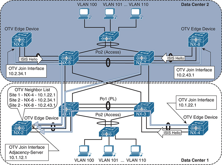
Figure 14-4 OTV EDs Register with the Adjacency Server
After the OTV Neighbor List (oNL) is built, it is advertised to each OTV ED from the adjacency server as shown in Figure 14-5.
Figure 14-5 OTV Adjacency Server Advertises the Neighbor List
Each OTV ED then establishes IS-IS adjacencies with all other OTV EDs. Updates are sent with OTV encapsulation in IP unicast packets from each OTV ED. Each OTV ED must replicate its message to all other neighbors. This step is shown in Figure 14-6.

Figure 14-6 OTV IS-IS Hellos in Adjacency Server Mode
Example 14-34 contains the output of show otv adjacency from NX-4. After receiving the OTV Neighbor List from the adjacency Server, IS-IS adjacencies are formed with all other OTV EDs.
Example 14-34 OTV Adjacency Server Mode IS-IS Neighbors
Overlay Adjacency database
Overlay-Interface Overlay0 :
Hostname System-ID Dest Addr Up Time State
NX-8 64a0.e73e.12c4 10.2.43.1 00:20:35 UP
NX-2 6c9c.ed4d.d942 10.1.12.1 00:20:35 UP
NX-6 6c9c.ed4d.d944 10.2.34.1 00:20:35 UP
An OTV IS-IS site adjacency is still formed across the site VLAN, as shown in the output of show otv site in Example 14-35.
Example 14-35 OTV Adjacency Server Mode Dual Adjacency
Dual Adjacency State Description
Full - Both site and overlay adjacency up
Partial - Either site/overlay adjacency down
Down - Both adjacencies are down (Neighbor is down/unreachable)
(!) - Site-ID mismatch detected
Local Edge Device Information:
Hostname NX-4
System-ID 64a0.e73e.12c2
Site-Identifier 0000.0000.0001
Site-VLAN 10 State is Up
Site Information for Overlay0:
Local device is AED-Capable
Neighbor Edge Devices in Site: 1
Hostname System-ID Adjacency- Adjacency- AED-
State Uptime Capable
-------------------------------------------------------------------------------
NX-2 6c9c.ed4d.d942 Full 00:42:04 Yes
Troubleshooting IS-IS adjacency and LSP advertisement problems in OTV adjacency server mode follows similar methodology as with OTV Multicast mode. The difference is that the packets are sent encapsulated in IP Unicast instead of multicast across the transport network.
Redundant OTV adjacency servers are supported for resiliency purposes. However, the two adjacency servers operate independently, and they do not synchronize state with each other. If multiple adjacency servers are present, each OTV ED registers with each adjacency server. An OTV ED uses the replication list from the primary adjacency server until it is no longer available. If the adjacency with the primary adjacency server goes down, the OTV ED starts using the replication list received from the secondary adjacency server. If the primary OTV ED comes back up before a 10-minute timeout, the OTV EDs revert back to the primary replication list. If more than 10 minutes pass, a new replication-list is pushed by the primary when it finally becomes active again.
OTV Control Plane Policing (CoPP)
OTV control plane packets are subject to rate-limiting to protect the resources of the switch, just like any other packet sent to the supervisor. Excessive ARP traffic or OTV control plane traffic could impact the stability of the switch, causing high CPU or protocol adjacency flaps, so protection with CoPP is recommended.
The importance of CoPP is realized when the OTV ARP-ND-Cache is enabled. ARP Reply messages are snooped and added to the local cache so the OTV AED can answer ARP requests on behalf of the target host. These packets must be handled by the control plane and could cause policing drops or high CPU utilization if the volume of ARP traffic is excessive. The OTV ARP-ND-Cache is discussed in more detail later in this chapter.
The show policy-map interface control-plane command from the default VDC provides statistics for each control plane traffic class. If CoPP drops are present and ARP resolution failure is occurring, the solution is typically not to adjust the control plane policy to allow more traffic, but to instead track down the source of excessive ARP traffic. Ethanalyzer is a good tool for this type of problem along with the event histories for OTV.
Understanding and Verifying the OTV Data Plane
OTV was designed to transport L2 frames between sites in an efficient and reliable manner. Frames arriving at an OTV ED are Unicast, Multicast, or Broadcast, and each type of frame must be encapsulated for transport to the destination OTV ED with information provided by the OTV control plane.
The default overlay encapsulation for OTV is GRE, shown in Figure 14-7. This is also referred to as OTV 1.0 encapsulation.

Figure 14-7 OTV 1.0 Encapsulation
When a frame arrives on the internal interface, a series of lookups are used to determine how to rewrite the packet for transport across the overlay. The original payload, ethertype, source MAC address, and destination MAC address are copied into the new OTV Encapsulated frame. The 802.1Q header is removed, and an OTV SHIM header is inserted. The SHIM header contains information about the VLAN and the overlay it belongs to. This field in OTV 1.0 is actually an MPLS-in-GRE encapsulation, where the MPLS label is used to derive the VLAN. The value of the MPLS label is equal to 32 + VLAN identifier. For this example, VLAN 101 is encapsulated as MPLS label 133. The outer IP header is added, which contains the source IP address of the local OTV ED and the destination IP address of the remote OTV ED.
Control plane IS-IS frames are encapsulated in a similar manner between OTV EDs across the overlay and also carry the same 42 bytes of OTV Overhead. The MPLS label used for IS-IS control plane frames is the reserved label 1, which is the Router Alert label.
Note
If a packet capture is taken in the transport, OTV 1.0 encapsulation is decoded as MPLS Pseudowire with no control-word using analysis tools, such as Wireshark. Unfortunately, at the time of this writing, Wireshark is not able to decode all the IS-IS PDUs used by OTV.
NX-OS release 7.2(0)D1(1) introduced the option of UDP encapsulation for OTV when using F3 or M3 series modules in the Nexus 7000 series switches. The OTV 2.5 UDP encapsulation is shown in Figure 14-8.
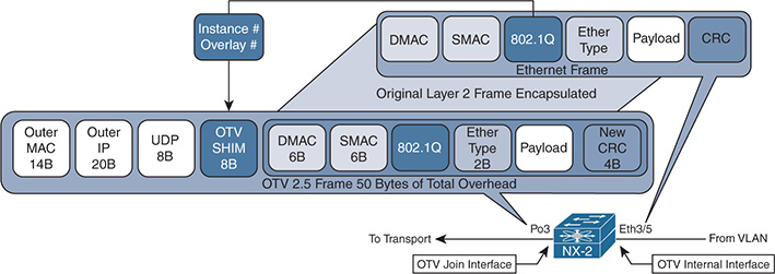
Figure 14-8 OTV 2.5 Encapsulation
Ethernet Frames arriving from the OTV internal interface have the original payload, ethertype, 802.1Q header, source MAC address, and destination MAC address copied into the new OTV 2.5 Encapsulated frame. The OTV 2.5 encapsulation uses the same packet format as Virtual Extensible LAN (VxLAN), which is detailed in RFC 7348.
The OTV SHIM header contains information about the Instance and Overlay. The instance is the table identifier that should be used at the destination OTV ED to lookup the destination, and the overlay identifier is used by the control plane packets to identify packets belonging to a specific overlay. A control plane packet has the VxLAN Network ID (VNI) bit set to False (zero), while an encapsulated data frame has this value set to True (one). The UDP header contains a variable source port and destination port of 8472.
Fragmentation of OTV frames containing data packets becomes a concern if the transport MTU is not at least 1550 bytes with OTV 2.5, or 1542 bytes with OTV 1.0. This is based on the assumption that a host in the data center has an interface MTU of 1500 bytes and attempts to send full MTU sized frames. When the OTV encapsulation is added, the packet no longer fits into the available MTU size.
The minimum transport MTU requirement for control plane packets is either 1442 for multicast transport, or 1450 for unicast transport in adjacency server mode. OTV sets the Don’t Fragment bit in the outer IP header to ensure that no OTV control plane or data plane packets become fragmented in the transport network. If MTU restrictions exist, it could result in OTV IS-IS adjacencies not forming, or the loss of frames for data traffic when the encapsulated frame size exceeds the transport MTU.
Note
The OTV encapsulation format must be the same between all sites (GRE or UDP) and is configured with the global configuration command otv encapsulation-format ip [gre | udp].
OTV ARP Resolution and ARP-ND-Cache
When a host communicates with another host in the same IP subnet, the communication begins with the source host resolving the MAC address of the destination host with ARP. ARP messages are shown between Host A and Host C, which are part of the same 10.101.0.0/16 subnet in Figure 14-9.
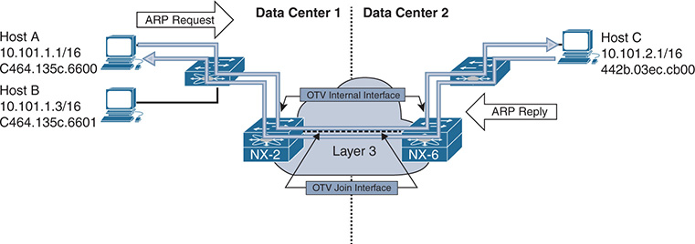
Figure 14-9 ARP Request and Reply
Host A broadcasts an ARP request message to the destination MAC address ff:ff:ff:ff:ff:ff with a target IP address of 10.101.2.1. This frame is sent out of all ports that belong to the same VLAN in the L2 switch, including the OTV internal interface of NX-2 and the port connected to Host B. Because NX-2 is an OTV ED for Data Center 1, it receives the frame and encapsulates it using the OTV control-group of 239.12.12.12. NX-2 also creates a MAC address table entry for Host A, known via the internal interface. Host A’s MAC is advertised from NX-2 across the overlay through the IS-IS control plane, providing reachability information to all other OTV EDs.
The control-group multicast frame from NX-2 traverses the transport underlay network until it reaches NX-6 where the multicast OTV encapsulation is removed and the frame is sent out of the OTV internal interface toward Host C. Host C processes the broadcast frame and recognizes the IP address as its own. Host C then issues the ARP reply to Host A, which is sent to NX-6. NX-6 at this point has an entry in the OTV MAC routing table for Host A with an IP next-hop of NX-2 since the IS-IS update was received. There is also a MAC address table entry for Host A in VLAN101 pointing to the overlay interface.
As the ARP reply from Host C is received at NX-6, a local MAC address table entry is created pointing to the OTV internal interface. This MAC address entry is then advertised to all remote OTV EDs through IS-IS, just as NX-2 did for Host A.
NX-6 then encapsulates the ARP reply and sends it across the overlay to NX-2 in Data Center 1. NX-2 removes the OTV encapsulation from the frame and sends it out of the internal interface where it reaches Host A, following the MAC address table of the VLAN.
The OTV ARP-ND-Cache is populated by listening to ARP reply messages. The initial ARP request is sent to all OTV EDs via the OTV control-group. When the ARP reply comes back using the OTV control-group, each OTV ED snoops the reply and builds an entry in the cache. If Host B were to send an ARP request for Host C, NX-2 replies to the ARP request on behalf of Host C, using the cached entry created previously, which reduces unnecessary traffic across the overlay.
Note
If multiple OTV EDs exist at a site, only the AED forwards packets onto the overlay, including ARP request and replies. The AED is also responsible for advertising MAC address reachability to other OTV EDs through the IS-IS control plane.
The ARP-ND-Cache is populated in the same way for multicast mode or adjacency server mode. With adjacency server mode, the ARP request and response are encapsulated as OTV Unicast packets and replicated for the remote OTV EDs.
If hosts are unable to communicate with other hosts across the overlay, verify the ARP-ND-Cache to ensure it does not contain any stale information. Example 14-36 demonstrates how to check the local ARP-ND-Cache on NX-2.
Example 14-36 Verify the ARP ND-Cache
OTV ARP/ND L3->L2 Address Mapping Cache
Overlay Interface Overlay0
VLAN MAC Address Layer-3 Address Age Expires In
101 442b.03ec.cb00 10.101.2.1 00:02:29 00:06:07
OTV also keeps an event-history for ARP-ND cache activity, which is viewed with show otv internal event-history arp-nd. Example 14-37 shows this output from the AED for the VLAN 100.
Example 14-37 ARP ND-Cache Event-History
ARP-ND events for OTV Process
02:33:17.816397 otv [9790]: [9810]: Updating arp nd cache entry in PSS TLVU.
Overlay:249 Mac Info: 0100-442b.03ec.cb00 L3 addr: 10.100.2.1
02:33:17.816388 otv [9790]: [9810]: Caching 10.100.2.1 -> 0100-442b.03ec.cb00 ARP mapping
02:33:17.816345 otv [9790]: [9810]: Caching ARP Response from overlay : Overlay0
02:33:17.816337 otv [9790]: [9810]: IPv4 ARP Response packet received from source 10.100.2.1 on interface Overlay0
02:33:17.806853 otv [9790]: [9810]: IPv4 ARP Request packet received from source 10.100.1.1 on interface Ethernet3/5
The OTV ARP-ND cache timer is configurable from 60 to 86400 seconds. The default value is 480 seconds or 8 minutes, plus an additional 2-minute grace-period. During the grace-period an AED forwards ARP requests across the overlay so that the reply refreshes the entry in the cache. It is recommended to have the ARP-ND cache time value lower than the MAC aging timer. By default, the MAC aging timer is 30 minutes.
It is possible to disable the OTV ARP-ND-Cache by configuring no otv suppress-arp-nd under the overlay interface. The result of this configuration is that all ARP requests are forwarded across the overlay and no ARP reply messages are cached.
Note
The ARP-ND-Cache is enabled by default. In some environments with a lot of ARP activity, it may cause the CPU of the OTV ED to become high or experience CoPP drops because the supervisor CPU must handle the ARP traffic to create the cache entries.
Broadcasts
Broadcast frames received by an OTV ED on the internal interface are forwarded across the overlay by the AED for the extended VLAN. Broadcast frames, such as ARP request, are encapsulated into an L3 multicast packet where the source address is the local OTV EDs join interface, and the group is the OTV Control-group address. The multicast packet is sent to the transport where it gets replicated to each remote OTV ED that has joined the control-group.
When using a multicast enabled transport, OTV allows for the configuration of a dedicated otv broadcast-group, as shown in Example 14-38. This allows the operator to separate the OTV control-group from the broadcast group for easier troubleshooting and to allow different handling of the packets based on group address. For example, a different PIM rendezvous point could be defined for each group, or a different Quality of Service (QoS) treatment could be applied to the control-group and broadcast-group in the transport.
Example 14-38 Dedicated OTV Broadcast Group
description Site A
otv join-interface port-channel3
otv data-group 232.1.1.0/24
otv extend-vlan 100-110
no shutdown
OTV EDs operating in adjacency server mode without a multicast-enabled transport encapsulate broadcast packets with an OTV unicast packet and replicate a copy to each remote OTV ED using head-end replication.
With either multicast or unicast transport, when the packet is received by the remote OTV ED, the outer L3 packet encapsulation is removed. The broadcast frame is then forwarded to all internal facing L2 ports in the VLAN by the AED.
Unknown Unicast Frames
The default behavior for OTV is to only flood frames to an unknown unicast MAC address on the internal interface. These packets are not forwarded across the overlay. This optimization is allowed because OTV operates under the assumption that there are no silent hosts, and an OTV ED sees traffic from all hosts eventually on the internal interface. After that traffic is received, it populates the MAC address table in the VLAN, and the MAC address is advertised by IS-IS to all OTV EDs.
There are situations where a silent host is unavoidable. To allow these hosts to function, OTV provides a configuration option to allow selective unicast flooding beginning in NX-OS 6.2(2). Example 14-39 provides a configuration example to allow flooding of packets to a specific destination MAC address in VLAN 101 across the overlay.
Example 14-39 Selective Unicast Flooding
feature otv
otv site-identifier 0x1
The result of adding this command is a static OTV route entry for the VLAN, which causes traffic to flow across the overlay, as shown in Example 14-40.
Example 14-40 OTV Routing Table with Selective Unicast Flooding
OTV Unicast MAC Routing Table For Overlay0
VLAN MAC-Address Metric Uptime Owner Next-hop(s)
---- -------------- ------ -------- --------- -----------
101 c464.135c.6600 0 00:02:38 static Overlay0
OTV Unicast Traffic with a Multicast Enabled Transport
Host-to-host communication begins with an ARP request for the destination, as shown previously in Figure 14-9. After this ARP request and reply exchange is finished, the OTV ED at each site has a correctly populated OTV MAC routing table and MAC address table for both hosts.
Figure 14-10 depicts the traffic flow in VLAN 103 between Host A in Data Center 1 and Host C in Data Center 2.

Figure 14-10 Unicast Host-to-Host Traffic Across OTV
Traffic from Host A is first sent to the L2 switch where it has an 802.1Q VLAN tag added for VLAN 103. The frames follow the MAC address table entries at the L2 switch across the trunk port to reach NX-2 on the OTV internal interface Ethernet3/5. When the packets arrive at NX-2, it performs a MAC address table lookup in the VLAN to determine how to reach Host C’s MAC address 442b.03ec.cb00. The MAC address table of NX-2 is shown in Example 14-41.
Example 14-41 MAC Address Table Entry for Host C
Note: MAC table entries displayed are getting read from software.
Use the 'hardware-age' keyword to get information related to 'Age'
Legend:
* - primary entry, G - Gateway MAC, (R) - Routed MAC, O - Overlay MAC
age - seconds since last seen,+ - primary entry using vPC Peer-Link, E - EVPN entry
(T) - True, (F) - False , ~~~ - use 'hardware-age' keyword to retrieve age info
VLAN/BD MAC Address Type age Secure NTFY Ports/SWID.SSID.LID
---------+-----------------+--------+---------+------+----+------------------
* 103 0000.0c07.ac67 dynamic ~~~ F F Eth3/5
O 103 64a0.e73e.12c3 dynamic - F F Overlay0
O 103 6c9c.ed4d.d943 dynamic - F F Overlay0
* 103 c464.135c.6600 dynamic ~~~ F F Eth3/5
The MAC address table indicates that Host C’s MAC is reachable across the overlay, which means that the OTV MAC Routing table (ORIB) should be used to obtain the IP next-hop and encapsulation details. The ORIB indicates how to reach the remote OTV ED that advertised the MAC address to NX-2 via IS-IS, which is NX-6 in this example.
Note
If multiple OTV EDs exist at a site, ensure the data path is being followed to the AED for the VLAN. This is verified with the show otv vlan command. Under normal conditions the MAC forwarding entries across the L2 network should lead to the AED’s internal interface.
NX-2 is the AED for VLAN103 as shown in Example 14-42.
Example 14-42 Verify the AED for VLAN 103
OTV Extended VLANs and Edge Device State Information (* - AED)
Legend:
(NA) - Non AED, (VD) - Vlan Disabled, (OD) - Overlay Down
(DH) - Delete Holddown, (HW) - HW: State Down
(NFC) - Not Forward Capable
VLAN Auth. Edge Device Vlan State Overlay
---- ----------------------------------- ---------------------- -------
100 NX-4 inactive(NA) Overlay0
101* NX-2 active Overlay0
102 NX-4 inactive(NA) Overlay0
After verifying the AED state for VLAN 103 to ensure you are looking at the correct device, check the ORIB to determine which remote OTV ED will receive the encapsulated frame from NX-2. The ORIB for NX-2 is shown in Example 14-43.
Example 14-43 Verify the ORIB Entry for Host C
OTV Unicast MAC Routing Table For Overlay0
VLAN MAC-Address Metric Uptime Owner Next-hop(s)
---- -------------- ------ -------- -------- -----------
103 0000.0c07.ac67 1 00:13:43 site Ethernet3/5
103 64a0.e73e.12c3 42 00:13:28 overlay NX-6
103 6c9c.ed4d.d943 42 00:02:56 overlay NX-6
103 c464.135c.6600 1 00:02:56 site Ethernet3/5
Recall that the ORIB data is populated by the IS-IS LSP received from NX-6, which indicates MAC address 442b.03ec.cb00 is an attached host. This is confirmed by obtaining the system-id of NX-6 in show otv adjacency, and then finding the correct LSP in the output of show otv isis database detail.
At the AED originating the advertisement, the redistribution from the local MAC table into OTV IS-IS is verified on NX-6 using the show otv isis redistribute route command, which is shown in Example 14-44.
At this point, it has been confirmed that NX-6 is the correct remote OTV ED to receive frames with a destination MAC address of 442b.03ec.cb00 in VLAN 103. The next step in delivering the packet to Host C is for NX-2 to rewrite the packet to impose the OTV header and send the encapsulated frame into the transport network from the join interface.
OTV uses either UDP or GRE encapsulation, and in this example the default GRE encapsulation is being used. There is a point-to-point tunnel created dynamically for each remote OTV ED that has formed an adjacency with the local OTV ED. These tunnels are viewed with show tunnel internal implicit otv detail, as shown in Example 14-45.
Example 14-44 MAC Table Redistribution into OTV IS-IS
OTV-IS-IS MAC redistribute route
Advertised into L1, metric 1 LSP-ID 6c9c.ed4d.d944.00-00
0103-6c9c.ed4d.d943, all
Advertised into L1, metric 1 LSP-ID 6c9c.ed4d.d944.00-00
Example 14-45 Dynamic Tunnel Encapsulation for NX-6
Admin State: up
MTU 9178 bytes, BW 9 Kbit
Tunnel protocol/transport GRE/IP
Rx
720357 packets input, 1 minute input rate 1024 packets/sec
Tx
715177 packets output, 1 minute output rate 1027 packets/sec
Last clearing of "show interface" counters never
The dynamic tunnels represent the software forwarding component of the OTV encapsulation. The hardware forwarding component for the OTV encapsulation is handled by performing multiple passes through the line card forwarding engine to derive the correct packet rewrite that includes the OTV encapsulation header.
Note
The verification of the packet rewrite details in hardware varies depending on the type of forwarding engine present in the line card. Verify the adjacencies, MAC address table, ORIB, and tunnel state before suspecting a hardware programming problem. If connectivity fails despite correct control plane programming, and MAC addresses are learned, engage the Cisco TAC for support.
After the OTV MAC-in-IP encapsulation is performed by NX-2, the packet traverses the Layer 3 transport network with a unicast OTV header appended. The source IP address is the join interface of NX-2 and the destination IP address is the join interface of NX-6. The Layer 3 packet arrives on the OTV join interface of NX-6, which must remove the OTV encapsulation and look up the destination.
The destination IP address of the outer packet header is the OTV join interface address of NX-6, 10.2.34.1. In a similar manner to the encapsulation of OTV, removing the OTV encapsulation also requires multiple forwarding engine passes on the receiving line card. Because the outer destination IP address belongs to NX-6, it will strip the outer IP header and look into the OTV shim header where the VLAN ID is found. The information from this lookup is originated from the ORIB, which contains the VLAN, MAC address, and destination interface, as shown in Example 14-46.
Example 14-46 ORIB Entry for Host C on NX-6
OTV Unicast MAC Routing Table For Overlay0
VLAN MAC-Address Metric Uptime Owner Next-hop(s)
---- -------------- ------ -------- --------- -----------
103 0000.0c07.ac67 1 4d00h site port-channel3
103 64a0.e73e.12c3 1 4d00h site port-channel3
103 6c9c.ed4d.d943 1 4d00h site port-channel3
103 c464.135c.6600 42 4d00h overlay NX-2
The next-pass through the forwarding engine performs a lookup on the VLAN MAC address table to find the correct outgoing interface and physical port. The MAC address table of NX-6 is shown in Example 14-47.
Example 14-47 MAC Address Table Entry for Host C on NX6
Note: MAC table entries displayed are getting read from software.
Use the 'hardware-age' keyword to get information related to 'Age'
Legend:
* - primary entry, G - Gateway MAC, (R) - Routed MAC, O - Overlay MAC
age - seconds since last seen,+ - primary entry using vPC Peer-Link, E - EVPN entry
(T) - True, (F) - False , ~~~ - use 'hardware-age' keyword to retrieve age info
VLAN/BD MAC Address Type age Secure NTFY Ports/SWID.SSID.LID
---------+-----------------+--------+---------+------+----+------------------
* 103 0000.0c07.ac67 dynamic ~~~ F F Po3
* 103 64a0.e73e.12c3 dynamic ~~~ F F Po3
* 103 6c9c.ed4d.d943 dynamic ~~~ F F Po3
O 103 c464.135c.6600 dynamic - F F Overlay0
The frame exits Port-channel 3 on the L2 trunk with a VLAN tag of 103. The L2 switch in data center 2 receives the frame and performs a MAC address table lookup to find the port where Host C is connected and delivers the frame to its destination.
Note
Troubleshooting unicast data traffic when using the adjacency server mode follows the same methodology used for a multicast enabled transport. The difference is that any control plane messages are exchanged between OTV EDs using a unicast encapsulation method and replicated by the advertising OTV ED to all adjacent OTV EDs. The host-to-host data traffic is still MAC-in-IP unicast encapsulated from source OTV ED to the destination OTV ED.
OTV Multicast Traffic with a Multicast Enabled Transport
OTV provides support for multicast traffic to be forwarded across the overlay in a seamless manner. The source and receiver hosts do not need to modify their behavior to exchange L2 multicast traffic across an OTV network between sites.
In a traditional L2 switched network, the receiver host sends an Internet Group Management Protocol (IGMP) membership report to indicate interest in receiving the traffic. The L2 switch is typically enabled for IGMP snooping, which listens for these membership reports to optimize flooding of multicast traffic to only the ports where there are interested receivers.
IGMP snooping must also learn where multicast routers (mrouters) are connected. Any multicast traffic must be forwarded to an mrouter so that interested receivers on other L3 networks can receive it. The mrouter is also responsible for registering the source with a rendezvous point if PIM ASM is being used. IGMP snooping discovers mrouters by listening for Protocol Independent Multicast (PIM) hello messages, which indicate an L3 capable mrouter is present on that port. The L2 forwarding table is then updated to send all multicast group traffic to the mrouter, as well as any interested receivers. OTV EDs use a dummy PIM Hello message to draw multicast traffic and IGMP membership reports to the OTV ED’s internal interface.
OTV maintains its own mroute table for multicast forwarding just as it maintains an OTV routing table for unicast forwarding. There are three types of OTV mroute entries, which are described as VLAN, Source, and Group. The purpose of each type is detailed in Table 14-2.
Type |
Definition |
(V, *, *) |
Created when a local mrouter is present in the VLAN, discovered by IGMP snooping. Used to forward traffic to the mrouter for all sources, and all groups. |
(V, *, G) |
Created when an IGMP membership report is received for group G. The interface on which the membership report was received is added to the Outgoing Interface (OIF) of the mroute. |
(V, S, G) |
Created when source S sends multicast traffic to group G, or as a result of receiving an IS-IS Group Membership Active Source (GMAS-TLV) with (S, G). |
The OTV IS-IS control plane protocol is utilized to allow hosts to send and receive multicast traffic within an extended VLAN between sites without the need to send IGMP messages across the overlay. Figure 14-11 shows a simple OTV topology where Host A is a multicast source for group 239.100.100.100, and Host C is a multicast receiver. Both Host A and Host C belong to VLAN 103.
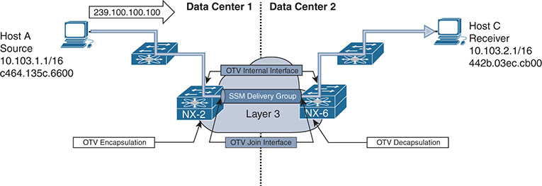
Figure 14-11 Multicast Traffic Across OTV with Multicast Transport
In this example, the L3 transport network is enabled for IP multicast. Each OTV ED is configured with a range of Source Specific Multicast (SSM) groups, referred to as the Delivery Group or data-group, which may be used interchangeably. The delivery group configuration of NX-6 is highlighted in the configuration sample provided in Example 14-48.
Example 14-48 OTV SSM Data-Groups
interface Overlay0
description Site B
otv join-interface Ethernet3/41
otv control-group 239.12.12.12
no shutdown
The delivery group must be coordinated with the L3 transport to ensure that PIM SSM is supported and that the correct range of groups are defined for use as SSM groups. Each OTV ED is configured with the same range of otv data-groups, and each OTV ED can be a source for the SSM group. Remote OTV EDs join the SSM group in the transport to receive multicast frames from a particular OTV ED acting as source. The signaling of which SSM group to use is accomplished with IS-IS advertisements between OTV EDs to allow for discovery of active sources and receivers at each site.
The site group is the multicast group that is being transported across the overlay using the delivery group. In Figure 14-11, the site group is 239.100.100.100 sourced by Host A and received by Host C. Essentially, OTV is using a multicast-in-multicast OTV encapsulation scheme to send the site group across the overlay using the delivery group in the transport network.
Troubleshooting is simplified by splitting the end-to-end packet delivery mechanism into two distinct layers of focus: the site group and the delivery group. At the source end, the site group troubleshooting is focused on ensuring that multicast data frames from the source are arriving at the internal interface of the AED for the VLAN. At the receiving site, site group troubleshooting must verify that a receiver has expressed interest in the group by sending an IGMP membership report. IGMP snooping must have the correct ports to reach the receivers from the OTV AEDs internal interface, through any L2 switches in the path. In the transport network, the delivery group must be functional so that any OTV ED acting as a source host successfully sends the multicast-in-multicast OTV traffic into the transport for replication and delivery to the correct OTV ED receivers.
For multicast sent by Host A to be successfully received by Host C, some prerequisite steps must occur. The OTV AED’s internal interface must be seen by the L2 switch as an mrouter port. This is required so that any IGMP membership reports from a receiver are sent to the AED, and any multicast traffic is also flooded to the AED’s OTV internal interface. To achieve this, OTV sends a dummy PIM hello with a source IP address of 0.0.0.0 on the internal interface for each VLAN extended by OTV. The purpose is not to form a PIM neighbor on the VLAN, but to force the detection of an mrouter port by any attached L2 switch, as depicted in Figure 14-12.

Figure 14-12 OTV Dummy PIM Hello Messages
An Ethanalyzer capture of the PIM dummy hello packet from NX-6 on VLAN 103 is shown in Example 14-49.
Example 14-49 Dummy PIM Hello Captured in Ethanalyzer
Type: IP (0x0800)
Internet Protocol Version 4, Src: 0.0.0.0 (0.0.0.0),Dst: 224.0.0.13 (224.0.0.13)
Version: 4
Header length: 20 bytes
Differentiated Services Field: 0xc0 (DSCP 0x30: Class Selector 6; ECN: 0x00:
Not-ECT (Not ECN-Capable Transport))
1100 00.. = Differentiated Services Codepoint: Class Selector 6 (0x30)
.... ..00 = Explicit Congestion Notification: Not-ECT (Not ECN-Capable
Transport) (0x00)
Total Length: 50
Identification: 0xa51f (42271)
Flags: 0x00
0... .... = Reserved bit: Not set
.0.. .... = Don’t fragment: Not set
..0. .... = More fragments: Not set
Fragment offset: 0
Time to live: 1
Protocol: PIM (103)
Header checksum: 0x3379 [correct]
[Good: True]
[Bad: False]
Source: 0.0.0.0 (0.0.0.0)
Destination: 224.0.0.13 (224.0.0.13)
Protocol Independent Multicast
0010 .... = Version: 2
.... 0000 = Type: Hello (0)
Reserved byte(s): 00
Checksum: 0x572f [correct]
PIM options: 4
Option 1: Hold Time: 0s (goodbye)
Type: 1
Length: 2
Holdtime: 0s (goodbye)
Option 19: DR Priority: 0
Type: 19
Length: 4
DR Priority: 0
Option 22: Bidir Capable
Type: 22
Length: 0
Option 20: Generation ID: 2882395322
Type: 20
Length: 4
Generation ID: 2882395322
Example 14-50 shows the IGMP snooping status of the L2 switch in Data Center 2 after receiving the PIM dummy hello packets on VLAN103 from NX-6.
Example 14-50 NX-6 Detected as an MROUTER Port by IGMP Snooping
Type: S - Static, D - Dynamic, V - vPC Peer Link
I - Internal, F - Fabricpath core port
C - Co-learned, U - User Configured
P - learnt by Peer
Vlan Router-port Type Uptime Expires
When Host C’s IGMP membership report message reaches NX-6, it is snooped on the internal interface and added to the OTV mroute table as an IGMP created entry. Remember that any switch performing IGMP snooping must forward all IGMP membership reports to mrouter ports.
Example 14-51 shows the OTV mroute table from NX-6 with the IGMP created (V, *, G) entry and Outgoing Interface (OIF) of Port-channel 3 where the membership report was received.
Example 14-51 OTV MROUTE State on NX-6
OTV Multicast Routing Table For Overlay0
(103, *, 239.100.100.100), metric: 0, uptime: 00:00:38, igmp Outgoing interface list: (count: 1)
NX-6 then builds an IS-IS message to advertise the group membership (GM-Update) to all OTV EDs. NX-2 in Data Center 1 receives the IS-IS GM-Update, as shown in Example 14-52. NX-6 is identified by the IS-IS system-id of 6c9c.ed4d.d944. The correct LSP to check is confirmed with the output of show otv adjacency, which lists the system-id of each OTV ED IS-IS neighbor.
Example 14-52 OTV IS-IS MGROUP Database on NX-2
OTV-IS-IS Process: default LSP database VPN: Overlay0
OTV-IS-IS Level-1 Link State Database
LSPID Seq Number Checksum Lifetime A/P/O/T
6c9c.ed4d.d944.00-00 0x00000002 0xFA73 1119 0/0/0/1
Instance : 0x00000000
Group-Address : IP Multicast : Vlan : 103 Groups : 1
Group : 239.100.100.100 Sources : 0
Digest Offset : 0
Note
At this point only Host C joined the multicast group, and there are no sources actively sending to the group.
NX-2 installs an OTV mroute entry in response to receiving the IS-IS GM-Update from NX-6, as shown in Example 14-53. The OIF on NX-2 is the overlay interface. The r indicates the receiver is across the overlay.
Example 14-53 OTV MROUTE Entry on NX-2
OTV Multicast Routing Table For Overlay0
(103, *, 239.100.100.100), metric: 0, uptime: 00:00:47, overlay(r)
Outgoing interface list: (count: 1)
Host A now begins sending traffic to the site group 239.100.100.100 in Data Center 1. Because of the PIM dummy packets being sent by NX-2, the L2 switch creates an IGMP snooping mrouter entry for the port. The L2 switch forwards all multicast traffic to NX-2, where its received by the OTV internal interface. The receipt of this traffic creates an OTV mroute entry, as shown in Example 14-54. The delivery group (S, G) is visible with the addition of the detail keyword. The source of the delivery group is the AED’s OTV join interface, and the group address is one of the configured OTV data-groups.
Example 14-54 OTV (V, S, G) MROUTE Detail on NX-2
OTV Multicast Routing Table For Overlay0
(103, *, *), metric: 0, uptime: 00:01:02, overlay(r)
Outgoing interface list: (count: 1)
Overlay0, uptime: 00:01:02, isis_otv-default
(103, *, 224.0.1.40), metric: 0, uptime: 00:01:02, igmp, overlay(r)
Outgoing interface list: (count: 2)
Eth3/5, uptime: 00:01:02, igmp
Overlay0, uptime: 00:01:02, isis_otv-default
(103, *, 239.100.100.100), metric: 0, uptime: 00:01:01, igmp, overlay(r)
Outgoing interface list: (count: 2)
Eth3/5, uptime: 00:01:01, igmp
Overlay0, uptime: 00:01:00, isis_otv-default
(103, 10.103.1.1, 239.100.100.100), metric: 0, uptime: 00:09:20, site
Outgoing interface list: (count: 1)
The OTV mroute is redistributed automatically into IS-IS, as shown in Example 14-55, where the VLAN, site (S,G), delivery (S,G), and LSP-ID are provided.
Example 14-55 OTV MROUTE Redistribution into OTV IS-IS
OTV-IS-IS process: default OTV-IS-IS IPv4 Local Multicast Group database
VLAN 103: (10.103.1.1, 239.100.100.100)
AS in LSP_ID: 6c9c.ed4d.d942.00-00
[DS-10.1.12.1, DG-232.1.1.0]
The redistributed route is advertised to all OTV EDs through IS-IS. Example 14-56 shows the LSP originated by NX-2, as received by NX-6.
Example 14-56 OTV MGROUP Database Detail on NX-6
OTV-IS-IS Process: default LSP database VPN: Overlay0
OTV-IS-IS Level-1 Link State Database
LSPID Seq Number Checksum Lifetime A/P/O/T
6c9c.ed4d.d942.00-00* 0x00000002 0x0110 1056 0/0/0/1
Instance : 0x00000004
Active-Source : IP Multicast : (103 - 10.1.12.1, 232.1.1.0) Groups : 1
Group : 239.100.100.100 Sources : 1
Source : 10.103.1.1
Digest Offset : 0
Note
The show otv isis internal event-history mcast command is useful for troubleshooting the IS-IS control plane for OTV multicast and the advertisement of groups and sources for a particular VLAN.
NX-6 updates this information into its OTV mroute table, as shown in Example 14-57. The s indicates the source is located across the overlay.
Example 14-57 OTV (V, S, G) MROUTE Detail on NX-6
OTV Multicast Routing Table For Overlay0
(103, *, *), metric: 0, uptime: 00:00:42, igmp, overlay(r)
Outgoing interface list: (count: 2)
Po3, uptime: 00:00:42, igmp
Overlay0, uptime: 00:00:41, isis_otv-default
(103, *, 224.0.1.40), metric: 0, uptime: 00:00:42, igmp, overlay(r)
Outgoing interface list: (count: 2)
Po3, uptime: 00:00:42, igmp
Overlay0, uptime: 00:00:40, isis_otv-default
(103, *, 239.100.100.100), metric: 0, uptime: 00:00:40, igmp, overlay(r)
Outgoing interface list: (count: 2)
Po3, uptime: 00:00:40, igmp
Overlay0, uptime: 00:00:38, isis_otv-default
(103, 10.103.1.1, 239.100.100.100), metric: 0, uptime: 00:08:58, overlay(s) Outgoing interface list: (count: 0)
Remote Delivery: s = 10.1.12.1, g = 232.1.1.0
The show otv data-group command is used to verify the site group and delivery group information for NX-2 and NX-6, as shown in Example 14-58. This should match what is present in the output of show otv mroute.
Example 14-58 Verify Site Group to Delivery Group Mapping
VLAN Active-Source Active-Group Delivery-Source Delivery-Group Joined-I/F
---- --------------- --------------- --------------- --------------- ----------
103 10.103.1.1 239.100.100.100 10.1.12.1 232.1.1.0 Eth3/41
NX-2# show otv data-group
---- ------------- ------------ --------------- --------------- ------- ------
103 10.103.1.1 239.100.100.100 10.1.12.1 232.1.1.0 Po3 Local
OTV EDs act as source hosts and receiver hosts for the delivery groups used on the transport network. An IGMPv3 membership report from the join interface is sent to the transport to allow the OTV ED to start receiving packets from the delivery group (10.1.12.1, 232.1.1.0).
Verification in the transport is done based on the PIM SSM delivery group information obtained from the OTV EDs. Each AED’s join interface is a source for the delivery group. The AED joins only delivery group sources that are required based on the OTV mroute table and the information received through the IS-IS control plane. This mechanism allows OTV to optimize the multicast traffic in the transport so that only the needed data is received by each OTV ED. The use of PIM SSM allows specific source addresses to be joined for each delivery group.
Example 14-59 shows the mroute table of a transport router. In this output 10.1.12.1 is NX-2’s OTV join interface, which is a source for the delivery group 232.1.1.0/32. The incoming interface should match the routing table path toward the source to pass the Reverse Path Forwarding (RPF) check. Interface Ethernet3/30 is the OIF and is connected to the OTV join interface of NX-6.
Example 14-59 MROUTE Verification in the Transport Network
IP Multicast Routing Table for VRF "default"
(10.1.12.1/32, 232.1.1.0/32), uptime: 00:02:29, igmp ip pim
Incoming interface: Ethernet3/29, RPF nbr: 10.1.13.1
Outgoing interface list: (count: 1)
Ethernet3/30, uptime: 00:02:29, igmp
Note
Multicast troubleshooting in the transport network between OTV ED sources and receivers follow standard multicast troubleshooting for the delivery group. The fact that OTV has encapsulated the site group within a multicast delivery group does not change the troubleshooting methodology in the transport. The OTV ED are source and receiver hosts for the delivery group from the perspective of the transport network.
OTV Multicast Traffic with a Unicast Transport (Adjacency Server Mode)
Deployments that rely on a unicast transport network can also forward multicast traffic across the overlay for extended VLANs. This is achieved by encapsulating the site group multicast packet into an IP unicast OTV packet across the transport network as depicted in Figure 14-13. If multiple remote sites have interested receivers, the source site OTV ED must perform head-end replication of the traffic and send a copy to each site, which becomes inefficient at scale.

Figure 14-13 Multicast Traffic Across OTV with Adjacency Server Mode
In this example, Host A and Host C are both members of VLAN 103. Host A is sending traffic to the site group 239.100.100.100, and Host C sends an IGMP membership report message to the Data Center 2 L2 switch. The L2 switch forwards the membership report to NX-6 because it is an mrouter port in IGMP snooping. The same PIM dummy hello packet mechanism is used on the OTV internal interface, just as with a multicast enabled transport. The arrival of the IGMP membership report on NX-6 triggers an OTV mroute to be created, as shown in Example 14-60, with the internal interface Port-channel 3 as an OIF.
Example 14-60 OTV (V, *, G) MROUTE Detail on NX-6
OTV Multicast Routing Table For Overlay0
(103, *, *), metric: 0, uptime: 00:03:25, igmp, overlay(r)
Outgoing interface list: (count: 2)
Po3, uptime: 00:03:25, igmp
NX-2 uptime: 00:03:24, isis_otv-default
(103, *, 224.0.1.40), metric: 0, uptime: 00:03:25, igmp
Outgoing interface list: (count: 1)
Po3, uptime: 00:03:25, igmp
The OTV mroute is then redistributed automatically into IS-IS for advertisement to all other OTV EDs, as shown in Example 14-61. The LSP ID should be noted so that it can be checked on NX-2, which is the OTV ED for the multicast source Host A in Data Center 1.
Example 14-61 OTV MROUTE Redistributed into OTV IS-IS on NX-6
OTV-IS-IS process: default OTV-IS-IS IPv4 Local Multicast Group database
VLAN 103: (*, *)
Receiver in LSP_ID: 6c9c.ed4d.d944.00-00
VLAN 103: IPv4 router attached
VLAN 103: (*, 224.0.1.40)
Receiver in LSP_ID: 6c9c.ed4d.d944.00-00
VLAN 103: IPv4 router attached
Note
There is a PIM enabled router present on VLAN 103, as indicated in Example 14-61 by the (*, *) entry.
Because IGMP packets are not forwarded across the overlay, the IS-IS messages used to signal an interested receiver are counted as IGMP proxy-reports. Example 14-62 shows the IGMP snooping statistics of NX-6, which indicate the proxy-report being originated through IS-IS. The IGMP proxy-report mechanism is not specific to OTV adjacency server mode.
Example 14-62 OTV IGMP Proxy Reports
Global IGMP snooping statistics: (only non-zero values displayed)
Packets received: 1422
Packets flooded: 437
STP TCN messages rcvd: 21
VLAN 103 IGMP snooping statistics, last reset: never (only non-zero values displayed)
Packets received: 1350
IGMPv2 reports received: 897
IGMPv2 queries received: 443
IGMPv2 leaves received: 10
PIM Hellos received: 2598
IGMPv2 leaves suppressed: 4
Queries originated: 4
Packets sent to routers: 902
vPC Peer Link CFS packet statistics:
IGMP Filtering Statistics:
Router Guard Filtering Statistics:
F340-35-02-N7K-7009-A-vdc_4#
Following the path from receiver to the source in Data Center 1, the IS-IS database is verified on NX-2. This is done to confirm that the overlay is added as an OIF for the OTV mroute. Example 14-63 contains the GM-LSP received from NX-6 on NX-2.
Example 14-63 OTV IS-IS MGROUP Database Detail on NX-2
OTV-IS-IS Process: default LSP database VPN: Overlay0
OTV-IS-IS Level-1 Link State Database
LSPID Seq Number Checksum Lifetime A/P/O/T
6c9c.ed4d.d944.00-00 0x00000005 0x7579 820 0/0/0/1
Instance : 0x00000003
Group-Address : IP Multicast : Vlan : 103 Groups : 2
Router-capability : Interested Vlans : Vlan Start 103 Vlan end 103
The IGMP Snooping table on NX-2 confirms that the overlay is included in the port list, as shown in Example 14-64.
Example 14-64 IGMP Snooping OTV Groups on NX-2
Type: S - Static, D - Dynamic, R - Router port, F - Fabricpath core port
Vlan Group Address Ver Type Port list
103 224.0.1.40 v3 D Overlay0
The OTV mroute on NX-2 contains the (V, *, G) entry, which is populated as a result of receiving the IS-IS GM-LSP from NX-6. This message indicates Host C is an interested receiver in Data Center 2 and that NX-2 should add the overlay as an OIF for the group. The OTV mroute table from NX-2 is shown in Example 14-65. The r indicates the receiver is reachable across the overlay. The (V, S, G) entry is also present, which indicates Host A is actively sending traffic to the site group 239.100.100.100.
Example 14-65 OTV MROUTE Detail on NX-2
OTV Multicast Routing Table For Overlay0
(103, *, *), metric: 0, uptime: 00:12:22, overlay(r)
Outgoing interface list: (count: 1)
NX-6 uptime: 00:12:21, isis_otv-default
(103, *, 224.0.1.40), metric: 0, uptime: 00:12:21, overlay(r)
Outgoing interface list: (count: 1)
NX-6 uptime: 00:12:21, isis_otv-default
Note
The OTV mroute table lists an OIF of NX-6 installed by OTV. This is a result of the OTV Unicast encapsulation used in adjacency server mode. The delivery group has values of all zeros for the group address. This information is populated with a valid delivery group when multicast transport is being used.
NX-2 encapsulates the site group packets in an OTV unicast packet with a destination address of NX-6’s join interface. The OTV unicast packets traverse the transport network until they arrive at NX-6. When the packets arrive at NX-6 on the OTV join interface, the outer OTV unicast encapsulation is removed. The next lookup is done on the inner multicast packet, which results in an OIF for the mroute installed by IGMP on the OTV internal interface. Example 14-66 shows the OTV mroute table of NX-6. The site group multicast packet leaves on Po3 toward the L2 switch in Data Center 2 and ultimately reaches Host C.
Example 14-66 OTV MROUTE Detail on NX-6
show otv mroute detail
OTV Multicast Routing Table For Overlay0
(103, *, *), metric: 0, uptime: 00:03:25, igmp, overlay(r)
Outgoing interface list: (count: 2)
Po3, uptime: 00:03:25, igmp
F340-35-02-N7K-7009-A-VDC2 uptime: 00:03:24, isis_otv-default
(103, *, 224.0.1.40), metric: 0, uptime: 00:03:25, igmp
Outgoing interface list: (count: 1)
Po3, uptime: 00:03:25, igmp
With adjacency server mode, the source is not advertised to the other OTV EDs by NX-2. This is because there is no delivery group used across the transport for remote OTV EDs to join. NX-2 only needs to know that there is an interested receiver across the overlay and which OTV ED has the receiver. The join interface of that OTV ED is used as the destination address of the multicast-in-unicast OTV packet across the transport. The actual encapsulation of the site group multicast frame is done using the OTV unicast point-to-point dynamic tunnel, as shown in Example 14-67.
Example 14-67 Dynamic Tunnel Encapsulation for Multicast Traffic
Tunnel16390 is up
Admin State: up
MTU 9178 bytes, BW 9 Kbit
Rx
663 packets input, 1 minute input rate 0 packets/sec
Tx
156405 packets output, 1 minute output rate 0 packets/sec
Last clearing of "show interface" counters never
Advanced OTV Features
Since its initial release as an NX-OS feature, OTV has continued to evolve. The next section in this chapter discusses some of the advanced features of OTV that allow it to be customized to meet the needs of different network deployments.
First Hop Routing Protocol Localization
First Hop Routing Protocols (FHRP), such as Hot Standby Routing Protocol (HSRP) and Virtual Router Redundancy Protocol (VRRP), are commonly used to provide a redundant default gateway for hosts on a VLAN. With OTV the VLAN has been extended across the overlay to multiple sites, which means that a router in Data Center 1 could form an HSRP neighbor with a router in Data Center 2. In addition, hosts in Data Center 2 could potentially use a default router that is physically located in Data Center 1, which results in unnecessary traffic crossing the overlay when it could be easily routed locally.
FHRP isolation is configured on the OTV EDs to allow each site’s FHRP to operate independently. The purpose of this configuration is to filter any FHRP protocol traffic, as well as ARP from hosts trying to resolve the virtual IP across the overlay. A configuration example from NX-2 is shown in Example 14-68.
Example 14-68 FHRP Localization Configuration on NX-2
ip access-list ALL_IPs
10 permit ip any any
ipv6 access-list ALL_IPv6s
10 permit ipv6 any any
mac access-list ALL_MACs
10 permit any any
ip access-list HSRP_IP
10 permit udp any 224.0.0.2/32 eq 1985
20 permit udp any 224.0.0.102/32 eq 1985
ipv6 access-list HSRP_IPV6
10 permit udp any ff02::66/128
mac access-list HSRP_VMAC
10 permit 0000.0c07.ac00 0000.0000.00ff any
20 permit 0000.0c9f.f000 0000.0000.0fff any
30 permit 0005.73a0.0000 0000.0000.0fff any
arp access-list HSRP_VMAC_ARP
10 deny ip any mac 0000.0c07.ac00 ffff.ffff.ff00
20 deny ip any mac 0000.0c9f.f000 ffff.ffff.f000
30 deny ip any mac 0005.73a0.0000 ffff.ffff.f000
40 permit ip any mac any
vlan access-map HSRP_Localization 10
match mac address HSRP_VMAC
match ip address HSRP_IP
match ipv6 address HSRP_IPV6
action drop
vlan access-map HSRP_Localization 20
match mac address ALL_MACs
match ip address ALL_IPs
match ipv6 address ALL_IPv6s
action forward
vlan filter HSRP_Localization vlan-list 100-110
mac-list OTV_HSRP_VMAC_deny seq 10 deny 0000.0c07.ac00 ffff.ffff.ff00
mac-list OTV_HSRP_VMAC_deny seq 11 deny 0000.0c9f.f000 ffff.ffff.f000
mac-list OTV_HSRP_VMAC_deny seq 12 deny 0005.73a0.0000 ffff.ffff.f000
mac-list OTV_HSRP_VMAC_deny seq 20 permit 0000.0000.0000 0000.0000.0000
route-map OTV_HSRP_filter permit 10
match mac-list OTV_HSRP_VMAC_deny
service dhcp
otv-isis default
vpn Overlay0
redistribute filter route-map OTV_HSRP_filter
otv site-identifier 0x1
ip arp inspection filter HSRP_VMAC_ARP vlan 100-110
Recall the topology depicted in Figure 14-1. In Data Center 1 HSRP is configured on NX-1 and NX-3 for all VLANs. HSRP is also configured between NX-5 and NX-7 for all VLANs in Data Center 2. The configuration in Example 14-68 is composed of three filtering components:
VLAN Access Control List (VACL) to filter and drop HSRP Hellos
ARP Inspection Filter to drop ARP sourced from the HSRP Virtual MAC
Redistribution Filter Route-Map on the overlay to filter HSRP Virtual MAC (VMAC) from being advertised through OTV IS-IS
FHRP isolation is a common source of problems due to incorrect configuration. Care should be taken to ensure the filtering is properly configured to avoid OTV IS-IS LSP refresh issues as well as duplicate IP address messages or flapping of the HSRP VMAC.
Multihoming
A multihomed site in OTV refers to a site where two or more OTV ED are configured to extend the same range of VLANs. Because OTV does not forward STP BPDUs across the overlay, L2 loops form without the election of an AED.
When multiple OTV EDs exist at a site, the AED election runs using the OTV IS-IS system-id and VLAN identifier. This is done by using a hash function where the result is an ordinal value of zero or one. The ordinal value is used to assign the AED role for each extended VLAN to one of the forwarding capable OTV EDs at the site.
When two OTV EDs are present, the device with the lower system-id is the AED for the even-numbered VLANs, and the higher system-id is the AED for the odd-numbered VLANs. The AED is responsible for advertising MAC addresses and forwarding traffic for an extended VLAN across the overlay.
Beginning in NX-OS 5.2(1) the dual site adjacency concept is used. This allows OTV EDs with the same site identifier to communicate across the overlay as well as across the site VLAN, which greatly reduces the chance of one OTV ED being isolated and creating a dual active condition. In addition, the overlay interface of an OTV ED is disabled until a site identifier is configured, which ensures that OTV is able to detect any mismatch in site identifiers. If a device becomes non-AED capable, it proactively notifies the other OTV ED at the site so it can take over the role of AED for all VLANs.
Ingress Routing Optimization
Egress routing optimization is accomplished with FHRP isolation. Ingress routing optimization is another challenge that needs to be considered in some OTV deployments. OTV allows a VLAN to be extended to multiple sites providing a transparent L2 overlay. This can result in a situation where more than one site is advertising the same L3 prefix to other sites, which may cause suboptimal forwarding.
Figure 14-14 shows that NX-11 has Equal Cost Multipath (ECMP) routes to reach the 10.103.0.0/16 subnet through either NX-9 or NX-10. Depending on the load-sharing hash, packets originating behind NX-11 reach either Data Center 1 or Data Center 2. If for example the destination of the traffic was Host C, and NX11 choose to send the traffic to NX-9 as next-hop, a suboptimal forwarding path is used. NX-9 then has to try to resolve where Host C is located to forward the traffic. The packets reach the internal interface of NX-2, which then performs an OTV encapsulation and routes the packets back across the overlay to reach Host C.

Figure 14-14 Suboptimal Routing Behavior
A common solution to this problem is to deploy OTV and Locator-ID Separation Protocol (LISP) together. LISP provides ingress routing optimization by discovering the location of a host and using the LISP control plane to advertise its location behind a specific Routing Locator (RLOC). LISP also provides options for supporting host mobility between sites. If a full LISP deployment is not required, LISP with Interior Gateway Protocol (IGP) assist can be used to redistribute routes from LISP into an IGP protocol.
Another solution to this problem is to advertise more specific, smaller subnets from each site along with the /16 summary to the rest of the routing domain. Routing follows the more specific subnet to Data Center 1 or Data Center 2, and if either partially fails, the /16 summary can still be used to draw in traffic. Assuming OTV is still functional in the partially failed state through a backdoor link, the traffic then relies on the overlay to cross from Data Center 1 to Data Center 2. The best solution to this problem depends on the deployment scenario and if the two OTV sites are acting as Active/Standby or if they are Active/Active from a redundancy perspective.
Note
For more information on LISP, refer to http://lisp.cisco.com.
VLAN Translation
In some networks, a VLAN configured at an OTV site may need to communicate with a VLAN at another site that is using a different VLAN numbering scheme. There are two solutions to this problem:
VLAN mapping on the overlay interface
VLAN mapping on an L2 Trunk port
VLAN mapping on the overlay interface is not supported with Nexus 7000 F3 or M3 series modules. If VLAN mapping is required with F3 or M3 modules, VLAN mapping on the OTV internal interface, which is an L2 trunk, must be used.
Example 14-69 demonstrates the configuration of VLAN mapping on the overlay interface. VLAN 200 is extended across the overlay. The local VLAN 200 is mapped to VLAN 300 at the other OTV site.
Example 14-69 VLAN Mapping on the Overlay Interface
interface Overlay0
description Site A
otv join-interface port-channel3
otv control-group 239.12.12.12
otv data-group 232.1.1.0/24
NX-2# show otv vlan-mapping
Original VLAN -> Translated VLAN
--------------------------------
200 -> 300
If F3 or M3 modules are being used, the VLAN mapping must be performed on the OTV internal interface, as shown in Example 14-70. This configuration translates VLAN 200 to VLAN 300, which is then extended across OTV to interoperate with the remote site VLAN scheme.
Example 14-70 VLAN Mapping on the L2 Trunk
interface Ethernet3/5
description 7009A-Main-VDC OTV inside
switchport
switchport mode trunk
switchport vlan mapping 200 300
mtu 9216
no shutdown
OTV Tunnel Depolarization
L3 routers with multiple ECMP routes to a destination apply a load-sharing hash function to choose an exit interface for a particular flow. A flow is typically the 5-tuple, which consists of the following:
L3 Source Address
L3 Destination Address
Layer 4 Protocol
Layer 4 Protocol Source Port
Layer 4 Protocol Destination Port
A problem typical to tunneled traffic is that it may become polarized as it traverses a multihop L3 ECMP network. These flows are referred to as elephants because they are typically moving a lot of traffic and can saturate single links of interface bundles, or of ECMP paths. Tunneled traffic uses a fixed 5-tuple because of the tunnel header and consistent source and destination address. This causes the input to the hash algorithm to stay the same, even though multiple diverse flows could be encapsulated inside the tunnel.
This polarization problem happens when each layer of the transport network applies the same hash function. Using the same inputs results in the same output interface decision at each hop. For example, if a router chose an even-numbered interface, the next router also chooses an even-numbered interface, and the next one also chooses an even-numbered interface, and so on.
OTV provides a solution to this problem. When using the default GRE/IP encapsulation for the overlay, secondary IP addresses can be configured in the same subnet on the OTV join interface, as shown in Example 14-71. This allows OTV to build secondary dynamic tunnels between different pairs of addresses. The secondary address allows the transport network to provide different hash results and load-balance the overlay traffic more effectively.
Example 14-71 Secondary IP Address to Avoid Polarization
interface port-channel3
description 7009A-Main-OTV Join
mtu 9216
no ip redirects
ip address 10.1.12.1/24
ip igmp version 3
The status of the secondary OTV adjacencies are seen with the show otv adjacency detail command, as shown in Example 14-72.
Example 14-72 OTV Adjacencies with Secondary IP Address
Overlay Adjacency database
Overlay-Interface Overlay0 :
Hostname System-ID Dest Addr Up Time State
NX-4 64a0.e73e.12c2 10.1.22.1 00:03:07 UP
Secondary src/dest: 10.1.12.4 10.1.22.1 UP
HW-St: Default
NX-8 64a0.e73e.12c4 10.2.43.1 00:03:07 UP
Secondary src/dest: 10.1.12.4 10.2.43.1 UP
HW-St: Default
NX-6 6c9c.ed4d.d944 10.2.34.1 00:03:06 UP
Secondary src/dest: 10.1.12.4 10.2.34.1 UP
HW-St: Default
Note
OTV tunnel depolarization is enabled by default. It is disabled with the otv depolarization disable global configuration command.
When OTV UDP encapsulation is used, the depolarization is applied automatically with no additional configuration required. The Ethernet frames are encapsulated in a UDP packet that uses a variable UDP source port and a UDP destination port of 8472. By having a variable source port, the OTV ED is able to influence the load-sharing hash of the transport network.
Note
OTV UDP encapsulation is supported starting in NX-OS release 7.2(0)D1(1) for F3 and M3 modules.
OTV Fast Failure Detection
OTV’s dual adjacency implementation forms an adjacency on the site VLAN as well as across the overlay for OTV EDs, which have a common site identifier. When an OTV ED becomes unreachable or goes down, the other OTV ED at the site must take over the AED role for all VLANs. Detecting this failure condition quickly minimizes traffic loss during the transition.
The site VLAN IS-IS adjacency can be configured to use Bidirectional Forwarding Detection (BFD) on the site VLAN to detect IS-IS neighbor loss. This is useful to detect any type of connectivity failure on the site VLAN. Example 14-73 shows the configuration required to enable BFD on the site VLAN.
Example 14-73 BFD for OTV IS-IS on the Site VLAN
feature bfd
otv site-vlan 10
interface Vlan10
no shutdown
ip address 10.111.111.1/30
The status of BFD on the site VLAN is verified with the show otv isis site command, as shown in Example 14-74. Any BFD neighbor is also present in the output of the show bfd neighbors command.
Example 14-74 Confirm BFD Neighbor on the Site VLAN
OTV-ISIS site-information for: default
OTV-IS-IS site adjacency local database:
SNPA State Last Chg Hold Fwd-state Site-ID Version BFD
64a0.e73e.12c2 UP 00:00:40 00:01:00 DOWN 0000.0000.0100 3
OTV-IS-IS Site Group Information (as in OTV SDB):
SystemID: 6c9c.ed4d.d942, Interface: site-vlan, VLAN Id: 10, Cib: Up VLAN: Up
Overlay State Next IIH Int Multi
Overlay1 Up 0.933427 3 20
Overlay Active SG Last CSNP CSNP Int Next CSNP
Overlay1 0.0.2.0 ffff.ffff.ffff.ff-ff 1d14h 00:00:02
Neighbor SystemID: 64a0.e73e.12c2
IPv4 site groups:
0.0.2.0
For the overlay adjacency, the presence of a route to reach the peer OTV ED’s join interface can be tracked to detect a reachability problem that eventually causes the IS-IS neighbor to go down. Example 14-75 shows the configuration to enable next-hop adjacency tracking for the overlay adjacency of OTV EDs, which use the same site identifier.
Example 14-75 Configuring OTV Next-Hop Adjacency Tracking
otv-isis default
redistribute filter route-map OTV_HSRP_filter
Example 14-76 contains the output of show otv isis track-adjacency-nexthop, which verifies the feature is enabled and tracking next-hop reachability of NX-4.
Example 14-76 Verify OTV Next-Hop Adjacency Tracking
OTV-IS-IS process: default
OTV-ISIS adjs for nexthop: 10.1.12.2, VRF: default
Hostname: 64a0.e73e.12c2, Overlay: Overlay1
This feature depends on a nondefault route, learned from a dynamic routing protocol for the peer OTV ED’s join interface. When the route disappears, OTV IS-IS brings down the adjacency without waiting for the hold timer to expire, which allows the other OTV ED to assume the AED role for all VLANs.
Summary
OTV was introduced in this chapter as an efficient and flexible way to extend L2 VLANs to multiple sites across a routed transport network. The concepts of MAC routing and the election of an AED were explained as an efficient way to solve the challenges presented by other DCI solutions without relying on STP. The examples and end-to-end walk-through for the control plane, unicast traffic, and multicast traffic provided in this chapter can be used as a basis for troubleshooting the various types of connectivity problems that may be observed in a production network environment.
References
Fuller, Ron, David Jansen, and Matthew McPherson. NX-OS and Cisco Nexus Switching. Indianapolis: Cisco Press, 2013.
Krattiger, Lukas. “Overlay Transport Virtualization” (presented at Cisco Live, Las Vegas 2016).
Schmidt, Carlo. “Advanced OTV—Configure, Verify and Troubleshoot OTV in Your Network” (presented at Cisco Live, San Francisco 2014).
draft-hasmit-otv-04 Overlay Transport Virtualization, H. Grover, D. Rao, D. Farinacci, V. Moreno, IETF, https://tools.ietf.org/html/draft-hasmit-otv-04, February 2013.
draft-drao-isis-otv-00 IS-IS Extensions to Support OTV, D. Rao, A. Banerjee, H. Grover, IETF, https://tools.ietf.org/html/draft-drao-isis-otv-00, March 2011.
RFC 6165, Extensions to IS-IS for Layer-2 Systems. A. Banerjee, D. Ward. IETF, https://tools.ietf.org/html/rfc6165, April 2011.
RFC 7348. Virtual eXtensible Local Area Network (VXLAN): A Framework for Overlaying Virtualized L2 Networks over L3 Networks. M. Mahalingam et al. IETF, https://tools.ietf.org/html/rfc7348, August 2014.
Cisco. Cisco Nexus Platform Configuration Guides, http://www.cisco.com.
Wireshark. Network Protocol Analyzer, www.wireshark.org/.