
Chapter 3
USB Inside Your Computer
What Does a USB Host Do?
In a system built with the Universal Serial Bus, the host computer is the single most important element present—it acts as the hardware liaison between each of the separate components of the USB. It is the responsibility of the host to maintain the state of bus and all peripherals attached to it. In short, the host manages the whole thing. There is only one host in each system.
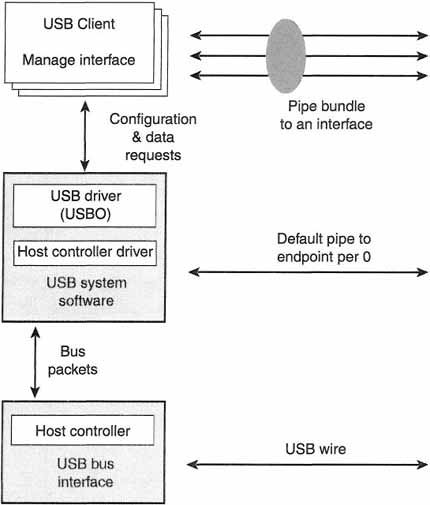
Within the host computer, there are a number of components (as is illustrated in Figure 3–1). The piece of hardware within the host computer that manages the physical part of the Universal Serial Bus is called the host controller. There is software on the USB host that is written to talk to the host controller, which in turn communicates with each of the attached USB devices (whether they are peripherals or hub devices). The Universal Serial Bus, from the host’s perspective, is shown in Figure 3–1.
Figure 3–1 USB Host Architecture
Each Universal Serial Bus system contains only one host; there are no provisions for host-to-host communication between machines in either the current specifications or implementations. There is talk within the USB standardization bodies and various USB implementers, however, of adding this support in future versions of the USB specification. Until that happens, this single-host limitation applies.
As we’ve already hinted, in a USB system the host manages data transfers between the client software and all the different and various USB devices that may be attached to the system. The USB host controller within the host computer performs a translation between the client’s (client software running on the host computer) view of data transfers and the actual USB transactions appearing on the physical bus. The USB host controller is also the component that manages the various physical USB resources (such as bandwidth). We’ll talk about the details as the chapter progresses.
The host system is divided into three major layers:
![]() The USB hardware interface
The USB hardware interface
![]() The USB system software (device drivers)
The USB system software (device drivers)
![]() The USB client software (peripheral-device drivers and application programs)
The USB client software (peripheral-device drivers and application programs)
The USB host controller, which is simply the physical-bus interface within the host computer, handles all the interactions between the host computer and the electrical and protocol layers of the Universal Serial Bus. The bus interface contains the same connection types as a USB hub. In fact, the host’s USB bus interface contains what is termed the root hub. This root hub provides attachment points to the host.
The system software on a Universal Serial Bus host system is divided into several different underlying pieces, and we’ll talk about each of these pieces in the coming sections. What you should understand now is that the primary responsibility of the USB system software is to provide a layer of abstraction above the actual implementation of the Universal Serial Bus. This layer of abstraction provides a consistent interface to the underlying hardware and buses without the client software having to be aware of the actual implementation details. In this regard, the system software is much like a normal device driver (or set of application programming interfaces) that may be provided by an operating-system vendor.
The client software, on the other hand, lives just above the device drivers and other system software. The only thing that the client software should be concerned with is that the USB device it is managing is working correctly. The client software should let the system software and bus interface hide the details of the bus protocols, configuration, and arbitration issues (all things we’ll cover a little later in this book). A properly implemented USB host system will make it a very easy job for people to develop client software that works well and easily with USB devices. That’s the goal, anyway. You should understand early on that the client software we’re talking about may be either a device driver or a simple user application running on host computer. The important thing, again, is that this piece of the puzzle is concerned only with the actual device, not the bus.
The host layers provide the following overall capabilities:
![]() The host detects when devices are attached and detached.
The host detects when devices are attached and detached.
![]() The host manages data-flow control on communication between the host and the USB devices.
The host manages data-flow control on communication between the host and the USB devices.
![]() The host manages data flow between the host and USB devices, collecting status and activity statistics.
The host manages data flow between the host and USB devices, collecting status and activity statistics.
![]() The host controls the electrical interfaces between the host controller and USB devices, including the provision of a limited amount of power.
The host controls the electrical interfaces between the host controller and USB devices, including the provision of a limited amount of power.
The Host Software
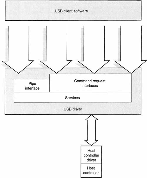
The software in the host controller is itself divided into three logical components (see Figure 3–2). These are:
Figure 3–2 Host Software Organization
![]() The USB device driver
The USB device driver
![]() The host application software
The host application software
We will call the various pieces of the software inside the USB host (taken as a whole) the software stack. The modules in the software stack are may be physically distinct from one another, but they are logically connected and communicate with one another. This is shown in Figure 3–2.
If you are at all familiar with the device-driver architecture of Windows NT, then you will no doubt notice the obvious similarities between the software layers we talk about in the following sections and the overall NT driver architecture. This is no accident, as most of the members of the USB standardization group are PC hardware and peripherals manufacturers. The USB specification documents even talk in terms of “IRPs” and other such “NT-isms”—terminology that we’ll spare you here. This isn’t to say that computers outside the Windows NT universe won’t embrace the USB standard, just that it was invented in the Windows world. Indeed, work is underway at Sun and other UNIX vendors to put the Universal Serial Bus on non-Windows platforms.
Host Controller Driver
The function of the host controller driver (or HCD in USB parlance) is to map the various possible host controller implementations into a USB host system. This allows the client software to work with the USB device for which it’s responsible without having to worry about the underlying hardware. With this model, both the USB driver and the client software can be written to work with an HCD-provided interface without having to deal with the actual hardware that the system builders put into the computer. This serves, in effect, to provide a hardware-independent abstraction layer.
Universal Serial Bus Driver
The USB Driver (or USBD in USB terminology) provides an interface to the host controller driver to provide a basic and generic interface to the host controller driver (HCD). This interface is known as the USBD Interface, or USBDI. While they may seem overwhelming at first, these acronyms are important, because all you will see if you read documentation or specifications from the USB standardization organizations or hardware vendors are these acronyms. Just to keep you used to them, this book will use them a lot. This book will also define them many times over.
There is also a defined interface between the host controller driver and the Universal Serial Bus driver. This interface is known as the host controller driver interface, or HCDI in USB-speak. Since the interface between these components is not used by any client software, and is operating-system and HCD dependent, it is not provided as a part of the Universal Serial Bus specification. An operating system (such as Windows 98 or Windows NT) may provide a single HCDI that supports various host controller implementations. In this way, the hardware is hidden under a single OS-dependent layer, allowing a single USBD on all hardware platforms supported by that operating system.
The USBD, like all device drivers, is nothing more than a collection of software routines used to manage communication with underlying hardware—in this case Universal Serial Bus devices. There is no other direct access within a USB system to the underlying hardware than through the USBD. An operating system may provide “pass-through” commands that allow a programmer or application to directly manipulate a device (this is done often in the SCSI world), but even these pass-through commands go through interfaces provided by the USBD.
A single, operating-system dependent, Universal Serial Bus driver communicates, arbitrates, and manages communication with USB devices on behalf of the client software (which may include USB peripheral device drivers for specific peripherals). Just one USBD exists to control all of the host controller hardware that may be present in a given system. As far as the client software is concerned, the USBD with which it communicates manages all of the attached devices as well.
The USBD communicates with attached USB devices and hubs through transport requests. These requests flow across mechanisms known as pipes. We talked about pipes a little bit in the last chapter. As a quick reminder, pipes are nothing more than virtual connections across virtual pathways called endpoints. These are USB abstractions and should be considered only in that context. These pipes certainly shouldn’t be confused with interprocess communication mechanisms (IPC) also called “pipes” that are provided by most modern operating systems.
Aside from providing a method for client software to transfer data to the USB devices, the USBD provides two groups of software mechanisms to clients: command mechanisms and pipe mechanisms. The command mechanisms provide the client software a pathway to configure and control general USB operation. The command mechanisms also allow the software a means to configure and generically control a USB device. In order to provide these services to the client software, the USBD owns what is known as the default pipe.
While the USBD uses pipe mechanisms to manage device-specific control and data transfers, client software is not allowed to communicate directly across a pipe. It is the absolute responsibility of the USBD to communicate over pipes and to translate requests and commands from the clients to the devices in order to send them over pipes.
This is a lot of information to digest about the USBD, but the important thing to remember is that the USBD is software that lives between the client software and the underlying hardware. A client cannot directly access the peripheral hardware or even the host’s USB controller hardware.
Initialization
Let’s spend a little time understanding what happens at system initialization time. Before we can do that we need to be consistent on what initialization is. System initialization happens when the computer system that is the USB host system is first powered on. Device initialization, on the other hand, occurs when a USB device is plugged into a Universal Serial Bus hub. It’s important to remember that the USB is “hot pluggable.” This means that devices can be added and taken off at the whim of the user, without powering the device or system down.
The steps that are taken to initialize the USB software stack during the initialization phase are completely operating-system dependent. There are as many different ways to initialize the host drivers and client software as there are software implementations. We’ll leave this topic alone in this book.
We do know what happens in the overall state of the Universal Serial Bus system as a whole, and within the various pieces of the system. On the host system, this means that certain management information is accumulated and collected when each Universal Serial Bus managed by that host is initialized (remember that there can be multiple Buses attached to a given host). A part of this management information provides for the default device address and its default pipe (which we have already talked about in the preceding sections).
To elaborate a bit further on this: when a device is first attached to the bus, it doesn’t yet know its device address—it is up to the host to give it one. Until this happens, the device responds to a special address known as the default address. In order for the host to communicate with the newly attached device, both the device’s default address and the default pipe must be available at the time that a device is attached to the bus. The host software creates the default device address and its default pipe whenever a USB is initialized.
Pipe Usage
A pipe is an association between the endpoint on a device and the USB host software. It’s a virtual connection of sorts. A pipe is also the perfect picture to have in your mind as you try to fathom the “plumbing” of a Universal Serial Bus system.
Each device has a unique set of pipes; they are not shared among devices. The endpoints that the pipes are constructed of are also unique to each device. Although the basic concept of a pipe is pretty much the same regardless of the device or the host software to which it is “connected,” some specific capabilities do exist between two broad groupings of pipes:
![]() Default pipes, which are owned and managed only by the USBD.
Default pipes, which are owned and managed only by the USBD.
![]() All other pipes, which are owned and managed by client software.
All other pipes, which are owned and managed by client software.
The default pipe for a device is never used directly by the client software. This does not mean, however, that the default pipe is not used by the USBD to satisfy some request on behalf of the client (the client issues requests to the USBD to achieve some device communication). The important thing to keep in mind here is that only the USBD driver uses default pipes, whether or not they’re used because of some request that a client might have made.
Buffers are required in order to move data around within the host system. Buffers, in this context, are nothing more than storage locations within the host system that are managed by the software. When one software component, such as a USB client, wants to issue a request or ask for data from a USB device, it allocates a buffer and passes it to the USBD. The USBD passes the buffer, along with the request of the USB peripheral, to the host controller driver (the HCD). The HCD handles the communication with the device and returns data in the buffer. The buffer is then passed back up through the USB software stack until it reaches the client Confusing as all this may sound when it you read it, the concepts of buffering are simple, as illustrated in Figure 3–3.

The USBD owns the responsibility of managing the buffers used to support transfers on the default pipe when, and only when, the client is not involved in the exchange of information with the device. An example of this occurs when the host needs to set the device address. If the client is involved in the transaction, such as when the host reads a device descriptor or asks for the device’s vendor ID, then the client must provide any required buffering.
If the USB driver does not own a pipe, then it can be owned by one or more client pieces. From the perspective of the USBD, a single client process owns the pipe. It would be completely acceptable for a group of clients to pool their resources to manage a single USB device. Such cooperating client processes must behave at all times as a single entity. In actual practice you will rarely, if ever, see multiple clients coordinating the usage of a single pipe.
One of the more important things to keep in mind when thinking about buffering is that USB devices can communicate at either low or full speeds. The buffers that hold the information used in bus transactions between the host and an attached device are used more frequently for a full-speed than for a low-speed device. This is only natural, considering that data is transferred much more quickly on a full-speed transfer. The client has to provide the appropriate amount of buffering to process the data-transfer speed of the pipe without losing pace with the device. The USB host software provides the client any additional buffering requirements for working space, or scratch space, that the client doesn’t provide.
Talking to Devices
The USB host must provide a variety of services to both client software and the attached devices and hubs. These are broadly grouped as follows:
![]() Device and hub configuration (through command mechanisms)
Device and hub configuration (through command mechanisms)
![]() Basic data transfers (via both command and pipe mechanisms)
Basic data transfers (via both command and pipe mechanisms)
![]() Status reporting and error recovery
Status reporting and error recovery
These are basic USB services and, like all USB services, they’re built around the ideas of pipes and endpoints.
Control and Command Mechanisms
Basic control transfers between the USB host and the USB devices are provided using something called a command mechanism. A command mechanism provides client software generic access to a USB device (“generic” meaning that the access is the same regardless of the type of attached device). A command mechanism is used to provide the client a means to read and write the control and data spaces within each attached USB device. To use a command mechanism, the client software simply tells the USBD which device to communicate with and, as we talked about in the preceding section, provides an empty buffer into which it puts the data.
An interesting aspect of the USBD command transfer is that a USB device does not have to be configured to use the mechanism. For example, many of the device-configuration operations used and provided by the USBD are command transfers.
Command mechanisms operate over pipes and, as with other types of pipes, the client can set the state of any given command pipe. These states are described in the next section.
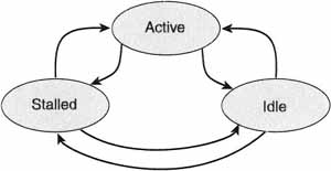
Pipe States
A pipe can be in any number of valid configurations. These valid configurations are known as Pipe States (Figure 3–4). These states are Active, Stalled, and Idle. It’s also important that you note that each pipe state has two components: a host status and a reflected endpoint status. Despite the complicated name, a reflected endpoint status is nothing more than the status at the USB device, while the host status is the status of the pipe at the host (of course!).
Figure 3–4 Pipe States
When a client asks for the status of a pipe, the host driver provides the statuses for both the host and reflected endpoints. The status of the pipe “reflected” from the device is the result of the pipe’s endpoint at the device itself being in a particular state. The client software manages the pipe state on the host. If the client wishes to change the state of the reflected endpoint, it must directly interact with the USB device endpoint to change that state. If this all sounds convoluted and confusing, look at the simple example shown in the Figure 3–5. In this example, an endpoint is changed from the STALLED state to the IDLE state.
Figure 3–5 Changing Reflected Endpoints

In the active state, the pipe’s policy has been set up and data can be transmitted over the pipe; transactions can occur at this point. The client can also ask the USBD (the USB driver) whether or not there are any transactions waiting to be sent between the USB device and the USB host. Even if there are no outstanding transactions, the pipe is still considered active. In fact, as long as transactions are possible, the pipe remains active.
At the opposite extreme from the active state is the stalled state. A pipe is stalled if an error has occurred on it. A pipe is also stalled if there is an error on the USB device’s endpoint. These are the only conditions for a stall.
A pipe is idle if it cannot accept further transfers. For a pipe to be truly idle, both the host and the USB device endpoint must agree that they are idle. An important point to consider when thinking about the idle pipe state is that nothing stands in the way of having that pipe transition back to the active state.
Except for error conditions, the state of a given pipe is controlled by the client software controlling the pipe. It’s important to remember that the only USBD-controlled pipe, the default pipe, is always in the active state. All other pipe states are controlled by client software. The client can set a pipe to either active or idle from any of the states we’ve already discussed. The client can also set the endpoint on the USB device to either an active or idle state. Clients can also abort or reset a pipe.
When a pipe is aborted, all transactions that are waiting to occur are immediately taken off the list of things to do by the USBD and returned to the client. At this point, the client is told that the transactions have been aborted. Neither the host state nor the reflected endpoint state of the pipe is affected when this abort occurs.
In addition to aborting a pipe, the client can cause the pipe to reset. When a pipe is reset, all of the pending and active transactions are immediately aborted (just as occurs when an “abort” is requested) and returned to the client. The host state is also set to active. The reflected endpoint status is not changed, but nothing stands in the way of allowing the client software to change it.
The Host Controller
The host controller is a piece of hardware within a USB host system that has the great responsibility of ensuring that everything flowing across the Universal Serial Bus cable is correct and within specification. If the software within the host is incorrect, then the worst that can happen is that a device becomes confused. If the host controller, on the other hand, doesn’t perform its actions correctly, then no device on the bus can be accessed.
Host controllers are independent of the attached devices and hubs. In every USB system, the host controller performs the exact same functional tasks. It serves both the USB host and the Universal Serial Bus itself. It brings the following functions to the system (all of which will be discussed further in this book):
![]() Handling all hardware and bus states
Handling all hardware and bus states
![]() Providing what is known as a serializer/deserializer
Providing what is known as a serializer/deserializer
![]() Generating USB frames for transmitting data over the bus
Generating USB frames for transmitting data over the bus
![]() Processing the data sent across the bus
Processing the data sent across the bus
![]() Managing the physical-bus protocol
Managing the physical-bus protocol
![]() Handling any transmission errors which may occur on the bus
Handling any transmission errors which may occur on the bus
Each of these host controller responsibilities is discussed in the following sections.
State Handling
As can well be imagined, a tremendous amount of information and states must be managed in a system as complex as the Universal Serial Bus. There are a large number of potential devices that can attached or removed at any given time. The devices can operate at one of two speeds. They may be bus powered or provide their own power source. It can get complicated fast. Fortunately, we have the host controller. It’s the responsibility of the USB host controller to manage the state of the Universal Serial Bus.
We’ve talked quite a bit about state information in this chapter, and it could all become confusing. A simple thing to remember is that each layer of abstraction has state information that must be maintained to keep that layer functioning. For example, the USBD (the driver) maintains state information that is specific to the endpoints and pipes being used to talk to the devices. The host controller, on the other hand, is concerned only with what’s happening on the wire at any given time; it does not understand such high-level concepts as pipes and endpoints. As such, it has only two primary things that it worries about: the root hub and statechange propagation.
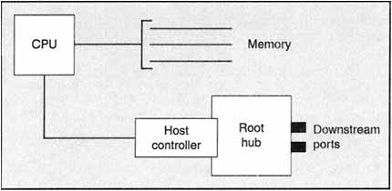
If you recall from our discussions in the previous chapter, the root hub is a USB hub that is embedded within each USB host system (see Figure 3–6). It is treated just like any other hub in the system, except that the host owns it. In fact, from a software perspective there is nothing special about the root hub. A full discussion of what hubs actually do is found in Chapter 4 of this book. What’s important to remember about the root hub in this discussion is that the host controller is the one responsible for maintaining the root hub’s state and state transitions.
Figure 3–6 Root Hub’s Place in a USB System
The condition of the host controller at any given point in time is tied completely to that of the root hub. The condition of the root hub is intimately tied to that of the Universal Serial Bus. If there is a state change within the host controller, and that change is visible to devices attached on the bus, then those changes must be propagated to the attached devices (this is called, as you recall, reflection). The overriding goal is to maintain consistency between what the host controller thinks the system looks like and what the devices think the system looks like.
Serializer and Deserializer
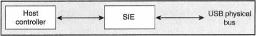
Communication between devices and hubs on the Universal Serial Bus occur as a serial bit stream; i.e., bits flow down the wire one at a time (as opposed to a parallel bit stream, where many bits may flow simultaneously). Within the host controller lives a piece of hardware that turns the internal data flow into a serial bit stream. This is called the serial interface engine (or SIE). In addition to serializing the bit stream, the SIE must also “deserialize” the bit stream. What this means is that the incoming serial bit stream is converted into a data stream that the host computer can understand (usually a parallel data stream). This process is diagrammed in Figure 3–7.
Figure 3–7 SIE in a USB System
Frame Generation
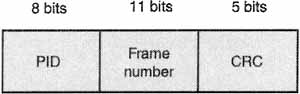
Sending a serial bit stream down a wire, as the SIE does, is one thing. It is quite another thing for that data to be in a format that devices can recognize and synchronize to. This is where the concept of “frames” comes into play. It is the responsibility of the host controller to partition data flowing across the USB into small quantities called frames. Frames are defined as a specific bit pattern that occurs over a known time quantity—1 ms in the USB world. The layout of a frame is shown in Figure 3–8.
Figure 3–8 Inside a USB Frame

The host controller creates frames by first issuing a bit pattern called a start of frame (or SOF) at 1-ms intervals. This start-of-frame marker is called a token. The SOF delimits the frame and marks its starting point. A USB device knows that every 1 ms it should look for a valid SOF pattern on the wire. If it doesn’t see one, then it waits another 1 ms until either it does see one, or it decides that there’s an error on the wire.
The SOF token is just the first part of the USB frame. After issuing the SOF token, the host controller then places data and commands to actual USB devices onto the bus. When the 1-ms time quantum has expired, it sends another SOF token and resumes the data transmissions. The only time that SOF tokens are not being sent down the wire is when the host controller is in a state where it is not providing power on the bus. There may be no power on the bus because the host has decided that, for some reason, it does not need to use the Universal Serial Bus. More likely, though, is that power-management functions on the host computer have put the computer into a “power-reduced” mode (this happens a lot on laptop computers).
The SOF token is the one thing on the bus that always holds priority. It is going to occur regardless of what else is occurring on the bus. In fact, there is an electrical circuit built into the hubs called “babble circuitry” that electrically isolates anything active on the bus between the end of a frame and the start of the next frame. This ensures an idle bus. We’ll talk more about the babble circuitry in the next chapter.
After the SOF token, each frame has an associated frame number. This frame number is generated by the host, and each frame has a frame number that is one more than the one before it. In other words, the frame number is incremented after each frame is transmitted. The host controller is responsible for this. The frame number is encoded into the lower 11 bits of the SOF token in a given frame. This is illustrated in Figure 3–9.
Figure 3–9 Layout of an SOF Token
This is a good time to define a couple of more terms. Babble is a phenomenon where a device speaks when it shouldn’t be speaking. The “babble circuitry” discussed in the previous paragraph, then, simply squelches this unwanted transmission. Babble is usually caused when a device loses track of how much time it’s spent on the bus (“lost the clock”), or is electrically unstable and is transmitting electrical noise down the wire (picture here static on your television set).
Another term is the end-of-frame interval (or EOF). This is the period of time between the last part of a frame transmission and the next SOF token. During the EOF interval, the host controller and all devices must cease transmission. When the EOF interval begins, any bus transactions that were scheduled for that frame are rescheduled for the next frame. If there is a bus transaction happening when the EOF interval rolls around, it is terminated and retried later.
Data Processing
The host controller is responsible for a certain amount of data processing. What this means is simply that the host controller must receive data from the USB and put data onto the USB. The host controller must interpret that data only as much as necessary in order to know to whom to give the data. The particular format used for communication between the various devices on the Universal Serial Bus and the host controller is implementation specific, and we won’t be discussing the host controller’s role in that.
Protocol Engine
We’ll mention the protocol engine because it’s a formal part of the host controller. It doesn’t really do anything beyond what we have already discussed. It reads each frame and manages the SOF and EOF processing for the host. It inserts whichever appropriate frame-level protocol information is required for outgoing transmissions. It isolates and interprets incoming protocol information. Chapter 6 discusses all of the protocol issues in depth. We’ll leave it alone as a topic until then.
Resource Allocation
As you will recall from our overview discussion in Chapter 2, the Universal Serial Bus supports the concept of guaranteed bandwidth for devices that need it; this is called isochronous bandwidth. For nonisochronous data (or asynchronous data), the Universal Serial Bus has what are called interrupt pipes.
The decision of whether a particular transaction will fit into a given frame is left up to the host controller. This is provided by algorithms, called heuristic algorithms, built into the system to estimate the amount of time that a given transaction will take. If the actual transaction time in the host controller exceeds the estimated value, then the host controller must ensure that frame integrity is kept. If the transaction takes longer than a single frame would take, then the host controller will separate the transaction into multiple frames.
To determine if the bandwidth for a requested transaction can be allocated, or to see if the transaction can fit into a frame, the host controller must calculate the maximum transaction execution time (no acronym this time!). This calculation requires the host-system software to provide certain information. This information is:
![]() The number of data bytes to be sent to the device
The number of data bytes to be sent to the device
![]() The type of transaction (e.g., data, control, etc)
The type of transaction (e.g., data, control, etc)
![]() The depth in the topology (i.e., where’s the packet going in the maze of devices?)
The depth in the topology (i.e., where’s the packet going in the maze of devices?)
The calculation also uses items determined by the host controller. These variables are derived by the host controller. The variables used in the equation include things like the bit transmission time, the signal-propagation delay through the various layers of USB devices and hubs, as well as any implementation-specific delays such as preparation and recovery times required by the host controller.
Configuration and Plug-n-Play
An important concept in the Universal Serial Bus world is that of plug-n-play. That means just what you might think; devices should be able to be plugged in and immediately recognized without any help from the user. The proper client software should be automatically loaded by the operating system to communicate with the special feature on the device. The host software should give it a name, and the device should be configured to operate on the particular Universal Serial Bus. These things comprise plug-n-play, and this section will discuss the things that happen within the host environment to make it happen.
Getting the Current Configuration
Every device in a Universal Serial Bus system has a configuration descriptor. This configuration descriptor is built and maintained by the Universal Serial Bus driver and is accessed through the USBD interface (USBDI). If a device is not configured, then of course there is no configuration descriptor for the USBI to give to callers. If a device is configured—and it almost always is—a descriptor is returned to the caller. This descriptor contains the following basic information:
![]() The configuration information stored on each device (this includes any alternate settings for the interfaces)
The configuration information stored on each device (this includes any alternate settings for the interfaces)
![]() Which of the alternate settings, if any, are being actively used.
Which of the alternate settings, if any, are being actively used.
![]() Pipe handles for the endpoints associated with any alternate settings
Pipe handles for the endpoints associated with any alternate settings
![]() Actual maximum transfer sizes for any given endpoint on the device
Actual maximum transfer sizes for any given endpoint on the device
In addition to this information, the configuration descriptor includes the maximum transmission size being used by the default pipe associated with that device. The maximum transmission size is the amount of data that a device can accept at once.
Configuration-management services are made available to client software as a set of commands. These commands, in turn, generate transactions on a device’s default pipe. The only exception occurs when an additional interrupt pipe may deliver the status of a hub directly to the hub driver (which is just another client software piece in the USB software stack). When there is a change in the state of a hub port, the hub begins an interrupt transfer; this occurs most frequently when a device has been either plugged into or removed from a hub’s port. Again, we’ll discuss hubs more fully in the next chapter.
Initial Device Configuration
A USB system cannot begin to configure a device until it knows that the device is present. The host is notified of a new device by the hub. It is the responsibility of the hub to ensure that this notification occurs. This happens as an interrupt transfer from the hub to the hub driver on the host. The hub driver on the host then notifies the USBD that there is a device that needs to be added to the list of available devices.
Each device on the Universal Serial Bus keeps a list of valid options and configurations that it will support. The configuration-management services accessible through the USBDI allow client software to initially set the device to one of its valid configurations. It is up to the USBD, however, to validate that the data-transfer rates given for all of the endpoints in the configuration do not exceed the capabilities of the USB with the current workload. It must also queue any pending transactions before allowing the new configuration to be set. If the host software decides that the selected configuration is unacceptable, it rejects it, and the device continues to be “not configured.” It is up to the client software to select a different configuration that may be acceptable by the host software.
Modifying a Device Configuration
As we’ve already mentioned, USB devices keep a list of valid configurations that they will accept. The configuration-management services allow software on the host to tell the USB to replace its current configuration with a valid configuration. The new configuration will come from the list of valid configurations for the device that the host maintains.
As with the initial device configuration, the host software must decide if the newly modified configuration will fit within the capabilities of the Universal Serial Bus. When this happens, the host must consider the current workload and schedule of transactions. If the new configuration is deemed inappropriate by the host software, then the previous (existing) configuration remains the one in use. Failing to modify a device configuration rarely causes the device to be put into the “not configured” state, though that is technically possible under the terms of the USB specification.
The Master Client
There is a concept in the USB host system that we haven’t talked about yet: the master client. The USB bus and the device configuration-management services allow any client to become the “master client” on the bus. What this really means is that a client can directly control certain bus parameters that you would normally associate with either the USBD or the HCD, such as adjusting the number of bit times in a frame on the bus.
A client becomes a “master client” when the USBD yields control so that the client can control its associated USB device. A master client gives up its powers either by explicitly requesting that it not be a master any more, or when the device the client is controlling is detached or reset. There can only be one master client at a time in a USB system, and they share a master token to decide who can actually adjust the SOF token. This master token is nothing more than a “talking stick” whose bearer has permission to alter the frame bit patterns.
The SOF is modified only when the device that the client is talking to supports the change. If the USB device being controlled by the master client does not support the change, then the change is, naturally, invalid. This should cause the master client to relinquish the “master” status. In addition, you should note that adjusting the SOF more than once every 6 ms (or six frames) causes undefined results.
Pipe and Bandwidth Management
It is the job of the host in a Universal Serial Bus system to manage the bandwidth of each pipe, as well as managing the pipes themselves. This responsibility falls naturally to the host, since the use of each USB device is driven by client software. The client software understands the usage of the device and creates the pipes as it needs them (a device will never need a pipe without client software to talk to).
It is also natural that the host manages the bandwidth on the USB bus. After all, the host is talking with up to 127 devices at a time. It is the host that must make decisions about how to partition the Universal Serial Bus to most efficiently communicate with all of these devices crying out for attention.
Service Capabilities
Pipe services provided by the USBDI offer clients the highest-speed, lowest-overhead transfer options available in the USB world. High performance is realized by shifting some of the management responsibilities to the client from the USBD (as we discussed earlier in the configuration section). The result is that pipes are implemented at a much more primitive level than the higher-level data-transfer services provided by the USBD command mechanisms. You should understand that pipe mechanisms through the USBDI do not allow direct access to a device’s default pipe.
Pipe-transfer services are useful, but only if the USB has been configured. For that reason, no pipe-transfer services are available until all device and bus configuration tasks have been successfully completed. As part of the device configuration, the USBD attempts to allocate the resources required to support the device pipes required by the selected configuration. The clients are then allowed to modify the configuration within the boundaries of the configuration discussion in the previous section.
Clients communicate with underlying pipe-transfer services with a combination of buffer “hand-offs” and status codes. For example, for an outgoing transfer the client populates a buffer with data it wants to send to a device and passes this to the USBD. The USBD then returns a status code indicating the success or failure after the transfer has been attempted.
Conversely, to execute an incoming pipe transfer (a “read” of the device), the client passes an empty buffer to the pipe service. The USBD returns both a populated buffer (populated with the data transferred from the device) and a status code indicating whether or not the data is valid. The status code also can indicate the quality of the data on an isochronous stream. We’ll talk more about quality of service in a later chapter.
Isochronous Data Transfers
We’ve already talked quite a bit about isochronous transfer, and we’ll continue to do so because it is one of the driving features of the Universal Serial Bus. As with other transfer services, all data is managed through the use of buffers. In an isochronous transfer each transfer buffer queued up for an isochronous pipe is a stream of data points (or samples). As isochronous transfers are used almost exclusively for digitized audio and video, this model makes sense. Remember that isochronous transfers are also called streaming transfers (and the pipes that carry these transfer are stream pipes).
As with all pipe transfers, the client decides what policies to use for the isochronous pipe, including the relevant service interval. If there are lost or missing bytes through the transmission process (detected when the data arrives), then these are noted to the client.
The client begins a streaming pipe transfer by first queuing a data buffer that will ultimately contain the data that is going to be transmitted over the bus. In order for continuous streaming to occur in an isochronous transfer, the client will queue an additional buffer of data before the currently queued buffer has been used and sent to the USB device. This type of scheme is known as “double buffering.”
When a client uses streaming data pipes, it is concerned about moving a stream of bits (or bytes) either from or to the USB device under its control. The client is not interested (nor should it be) in the actual packetization of the data as it flows across the wire. This is usually invisible to the client software, and data for a transaction is always completely contained within some client data buffer. Note that while the packetization is normally invisible to the client, the USB specification provides that the “packet view” of the data is available should the client ask to see it. This occurs infrequently in practice.
Interrupt Transfers
Universal Serial Bus devices communicate asynchronously with the host system (i.e., when the host system least expects it!). When there is information to send that the host did not ask for, or did not want to wait for, devices on the Universal Serial Bus uses what are called interrupt transfers.
Interrupt transfers always originate in some USB device. They are routed through the host software to the client responsible for the device. The client is then notified by the pipe service component in the USBDI that there is an interrupt transfer for his device. The client should provide a buffer large enough to hold the interrupt-transfer data (the transfer is usually accomplished in a single USB transaction). Once the data is placed into the buffer, the USBDI then passes the buffer back to the client for processing.
Bulk Transfers
To move large amounts of data between a device and the client software living on the host system, the Universal Serial Bus uses bulk transfers. These transfers can be initiated either by a USB device or by the client software on the host. No bandwidth or timing guarantees are made about the data exchanged in a bulk transfer. Data from bulk transfers are moved between the client and the USBD through buffers and the USBD Interface. As the data is pretty much application dependent, there isn’t much more to say about such transfer here except that it occurs. Nothing in the Universal Serial Bus, excepting the client software, attempts to interpret any data flowing across the bus.
Control Transfers
When software on the host system wants to set the configuration of a device, or otherwise control it, the host issues control transfers. Control transfers are bidirectional message pipes that are used in two stages. First, the client initiates a “setup stage” to the device endpoint, preparing it to use whatever data is about to follow. Then a data stage is executed to either bring data in from the device or send data to the device. Please keep in mind that the data stage is optional and depends upon the control function being exercised.
From the client’s perspective, the client must prepare a buffer laying out the command phase and any data buffer space it might need to satisfy the command when using USBDI interfaces to initiate control transfers. The client receives notification from the underlying drivers when the control transfer is complete.
Handling Errors
In the normal case of operation for any complex system, errors will occur. The graces with which errors are tolerated and corrected mark the robustness of the system. The Universal Serial Bus is a complex system and as such will encounter errors.
The host controller will detect a number of transaction errors. These errors are defined and described from the host’s point of view. The steps taken to address each error are the same for each type. These will be addressed at the end of this discussion.
The transaction errors that may be encountered in a Universal Serial Bus system are:
![]() Time-out conditions after a host-transmitted token or packet
Time-out conditions after a host-transmitted token or packet
![]() Data errors resulting in missed or invalid transactions
Data errors resulting in missed or invalid transactions
![]() Protocol errors
Protocol errors
Time-out conditions occur when the host controller initiates a transaction and the device never responds. This can be caused when the device endpoint that is being used becomes unresponsive (e.g., the cable is disconnected, the power turned off, etc). A time-out condition can also occur when the structure of a transaction is so badly damaged that the targeted endpoint does not recognize it (e.g., this would be the case if electrical interference badly garbled the transaction).
On the Universal Serial Bus there can also be data errors resulting in missing or invalid transactions across the bus. An example would be the host controller’s sending or receiving a packet shorter than what was expected. Another example would be an invalid checksum on the received data packet.
The final type of transmission error that can occur is a protocol error. Such errors arise from events such as invalid handshaking, false end-of-packet (EOP) delimiters, or even bit-stuffing errors. We haven’t spent a great deal of time discussing the bus protocol just yet (we will do that in Chapter 7), so we’ll leave these conditions unexplained for now.
We deal with each of these errors in a consistent fashion for each of the different transaction types. The host maintains a count of the errors for each transaction that occurs. This counter reflects the number of times the transaction encountered each error type. If the error count reaches three for a given error type, then the host aborts the transfer and returns an error to the client. A given implementation of a Universal Serial Bus host may allow the user to set the transaction-error threshold to a value other than three. Retransmission will handle most common and transient errors (such as would be caused by electrical interference on the cables).
It’s important to remember that the error counter is directly related to the type of error. If you have multiple errors occurring on a transaction, then there will be multiple error counters. Only after you have three of the same type of error will the transaction be aborted.
Wrapping It Up
This chapter has covered a lot of territory. By now, you understand that responsibility falls upon the many varied layers within the host computer to manage the Universal Serial Bus. The host is divided into three pieces: the host controller, the USB driver, and the client software. Each manages its own piece of the USB puzzle.
The host detects when devices are plugged in (with a little help from the hubs, which we’ll cover in the next chapter) and when they are removed from the bus. The host manages the bandwidth and flow control across that bus, as well. Finally, the host manages the pipes used for communication and provides the software that the bus actually uses.
The host cannot do any of this alone. It needs the complete cooperation of USB devices and hubs. We’ll get into those areas next.