
Chapter 4
Inside a USB Hub
What Does a USB Hub Do?
Hubs in the Universal Serial Bus world provide the connection point between devices and the host. All devices plug into hubs, and hubs plug into either the host or other hubs (creating a tiered layer of hubs). The host even has an integrated hub, known as the root hub. The hub supports many of the attributes that make the Universal Serial Bus easy to use, and it helps to hide the complexity of the USB from the end user. It should be noted up front that, as far as the USB is concerned, the hub is just another USB device (which we’ll cover in the next chapter). While the hub may be just a device, it is a device with special responsibilities.
Among the functions that the hub provides to the USB are:
![]() Device connectivity
Device connectivity
![]() Power-management functions
Power-management functions
![]() Device attachment/removal detection
Device attachment/removal detection
![]() Bus-error detection and recovery
Bus-error detection and recovery
![]() Full- and low-speed device support
Full- and low-speed device support
As you can see in Figure 4–1, a hub consists of a hub repeater and a hub controller. It’s up to the hub repeater to manage the setup and destruction of connections to and through the hub. It is also the responsibility of the hub repeater to support error handling and recovery (e.g., bus fault detection, etc.). The repeater, further, is the component within the hub that detects whether a device has been attached or removed.

The hub controller, on the other hand, primarily provides the interface between the functionality of the hub and the rest of the Universal Serial Bus. It is the hub controller that formats commands to be sent across the bus and communicates with the host. There are hub-specific status registers and device-control requests on the hub that permit the host software to configure it through software commands sent over the USB. These status registers also allow the host system to monitor what is happening downstream of the hub, on its attached devices.
You will also notice, looking at Figure 4–1, a root port and some number of downstream ports. The root port points toward the host computer (in the upstream direction). Devices attached to the hub attach to the downstream ports. We’ll talk about upstream, downstream, and the root port throughout this chapter (and the rest of this book), so you should be clear on what these directions are.
How Hubs Handle Packets
Unlike “normal” USB devices, which serve to provide some concrete function to client software on the host, a hub is more of a “middle man.” The hub accepts packets and forwards them to an attached device that can use them. It also serves to move data from devices attached to it back to the host. While this is the primary responsibility of the hub, it also accepts and generates packets itself to make sure that the devices and host have a completely clear virtual pathway between them. Probably the biggest difference between the hub and devices that provide function is that hubs are controlled primarily by the host system software, while USB devices answer to client software that controls them.
The piece of the hub that handles packets is the hub repeater. While there may be any number of downstream ports for USB devices to attach to, there is at most one port in the upstream direction (called the root port) that sends data to the host. Remember, upstream is toward the host and downstream is toward the attached devices (away from the host). Figure 4–2 shows how packets move through the hub repeater in both directions.
Figure 4–2 Hub Connectivity

The hub is constantly sending and receiving packets between the attached devices and the host system. The hub also has an idle state during which the hub does not pass packets. When in the idle state each port on the hub sits and waits for the start of the next packet.
When there is a device attached to the port in the hub, that port is considered enabled. Contrarily, when there is no device attached, the port is considered disabled. If a downstream hub port is enabled and the hub notices a start of packet on that port, then the hub opens the pathway to the host. The hub establishes connectivity upstream through the root port, but not to any other downstream ports. Devices can talk only to the host, not to other devices. Other devices downstream never see packets between the host and a device.
When the hub detects start-of-packet activity on an upstream port to a given port on the hub, all other downstream ports are locked. This ensures that nothing on the hub will be modified until the packet of data has been communicated to the device (detected by an end of packet, or EOP, on the wire).
When the hub detects an SOP on its root port, on the other hand, it operates in a broadcast mode. The hub establishes connectivity to all of the ports that have devices attached. Any port that is not enabled does not receive any packets from the root port (and doesn’t send any either)—a policy that makes sense, since there’s likely no device attached to the port!
Maintaining State on Ports
A downstream port on a hub is, at any given time, in one of several possible states. The port may be enabled, suspended, reset, or in any number of other defined states. The hub, since at heart it is just another USB device, maintains a device state that is hub specific. We’ll talk about this device state in the next chapter. Our present discussion is focused on the possible states that the hub maintains on each individual downstream port. The root port is always “wide open” and does not support any of the states that we are talking about here. We are talking only about downstream port state. This is illustrated in Figure 4–3.
Figure 4–3 Hub-State Diagram

The states that a downstream port on a hub can be in are as follows:
![]() Powered off—no power applied to device
Powered off—no power applied to device
![]() Disconnected—device is not logically connected to the USB
Disconnected—device is not logically connected to the USB
![]() Disabled—device may be attached to port but it isn’t being recognized
Disabled—device may be attached to port but it isn’t being recognized
![]() Enabled—device is attached to the port and can be used
Enabled—device is attached to the port and can be used
![]() Suspended—device is attached but is “asleep”
Suspended—device is attached but is “asleep”
We’ll talk about each of these states in depth in the sections below.
Powered-Off State
Some ports on a hub have support for power switching, and some do not. Power switching means that the hub can selectively apply or remove power from each port. This switching is done because there is only a certain amount of bus power available, and intelligent hubs and devices can limit the amount of power they consume in order to give more power to other devices.
A port is set to the powered-off state at the request of the host. This setting is normally used when the host goes into a power-saving mode, such as a laptop going into a suspended state. The host sends a request, called ClearPortFeature (PORT_POWER), to set the port to a powered-off state. Also, the hub transitions the port from its current state to a powered-off state when it detects a reset signal on its root port. When the hub receives a reset signal, it reverts to its default power-on state. After a reset, the host must completely reconfigure each device and hub (remember, a hub is just a device) on the Universal Serial Bus. This procedure is called bus enumeration and is discussed at length in the next two chapters. Finally, a port becomes powered off when power to the hub is first applied (which seems counterintuitive, but isn’t when you think in terms of the hub resetting itself).
All of the electrical signals from a port that is in the powered-off state are ignored by the hub (i.e., even signals from self-powered devices are ignored in the powered-off state). The port is treated as dead in this state, and all upstream activity from the host to that port is ignored. If there is upstream traffic, then you should worry about the coherency of your host software (it should know when it powers off a port and not try to talk to it)!
Disconnected State
A hub port is in the disconnected state when the port has power but has no device attached. A port transitions from the powered-off state to the disconnected state when the host tells the hub to apply power to the port (via a SetPortFeature(PORT_POWER) request). If the hub doesn’t allow individual power control on each port, then the disconnected state is the default state of each port of the hub. This means that each port will be put into the disconnected state when the hub is either reset or first powered up.
When a port is in the disconnected state, it doesn’t communicate in either the upstream or downstream directions. The port can, however, detect a connect event. The connect event causes the port to transition to the disabled state. A connect event is triggered when a device is plugged into a port on the hub.
Disabled State
A hub port is put into the disabled state when the hub detects a device being attached (a connect event). This assumes that the port is currently in the disconnected state, which means that it must be powered on (if the hub supports per-port power switching).
A device plugged into a port that is the disabled state cannot talk to the host, but the host can talk to it through the use of a reset signal. At all other times, the cabling to the device is electrically isolated from the rest of the hub. Certain events, though, may allow upstream signaling to be resumed. One such event is a disconnect event.
Enabled State
A port transitions to the enabled state when the host tells the hub to put the port into the enabled state. This is done as a part of the bus-enumeration process, where the USB device is actually recognized by the host computer. This process occurs when the host sends either a PORT_ENABLE or PORT_RESET request to the hub (for a full discussion of these requests, see Chapter 6). Since the port can transition to the enabled state only from the disabled state, the port can never become enabled if there is not a device attached to it.
When the port is in the enabled state, packets may flow in both directions (upstream and downstream) from the attached device. The downstream traffic includes full-speed traffic, low-speed traffic (within the constraints described later in this chapter), and all reset signaling. The upstream traffic on an enabled port includes all full- and low-speed packets, as well as any resume signaling.
A port leaves the enabled state and reenters the disabled state if it the host tells it to (through a PORT_ENABLE request). This also happens if an error is detected on the bus. The hub will transition an enabled port to the disconnected state if the hub detects the port being removed (a disconnect event).
Suspended State
A device can be temporarily put into a suspended state to keep power from being applied to it. This is different from the powered-off state. The suspended state is used for power management, whereas the powered-off state is used when no device is attached to the port. A hub port can be put into the suspended state by either the host requesting that it happen or the device deciding it wants to be suspended.
The hub will suspend a downstream port when it receives a PORT_SUSPEND request from the host. If this happens, the hub “holds” the suspend request until the current transaction to or from the device is complete. A hub may itself be suspended, but that state is maintained separately from each port’s suspended state.
If the hub on which the suspended port lives is itself suspended, an attempt to communicate with the port will cause the hub to wake up before the port wakes up. If, on the other hand, the hub is already awake, then the port is awakened. This allows a chain of hubs to be suspended and then wakened up by means of a simple communication with a device at the bottom of the hierarchy, which in turn serves to simplify the host software design.
If a disconnect event occurs while a port is suspended, the hub will transition the port to the disconnected state. It is not possible to transition from a disconnected state into the suspended state.
Bus Signaling Behavior
As we discussed in the introductory chapters, devices can operate at either full speed or low speed. Packets can flow at very different data rates one right after another on the bus. There must be some mechanism in place to keep devices on the Universal Serial Bus from becoming confused and to keep everything synchronized.
To properly manage both full- and low-speed devices, the hub must detect the speed at which a device wishes to operate. The hub will detect whether a device is full or low speed when the device is first connected to its port on the hub, or when the device is powered up. This detection is done electrically, not through the software. If you remember from our brief hardware description in Chapter 2, there are two data lines in a USB cable, D+ and D-. One of these is pulled into the “low state.” If the D- signal is high, then the device uses low-speed signaling. Conversely, if the D+ line is high, then the device uses full-speed signaling.
It is important, so as not to confuse low-speed devices, that full-speed traffic not be sent to low-speed devices. The reason is that a low-speed device might mistakenly respond to the signaling and create a bus conflict. On the other hand, low-speed traffic will never confuse a full-speed device, since a valid packet ID (PID) cannot be constructed from low-speed data patterns. The hub and the host always use full-speed signaling.
If a low-speed device is attached to a port, then the hub must generate something called a low-speed keep-alive strobe. Generated at the beginning of each transmitted frame, low-speed devices use the strobe to keep from going into the suspended state from lack of bus traffic. The hub repeater generates the keep-alive strobe from internal circuitry.
The keep-alive strobe is generated just one time per frame, and it must obey the following rules:
1. When entering the suspended state, the keep-alive strobe must not disappear before the last frame.
2. The hub is allowed to create only three strobes after the last frame.
3. The keep-alive strobe must happen no later than one frame after the hub is no longer suspended.
Fault Recovery in the Hub
Since the hub lives between the host and any attached devices on the Universal Serial Bus, it is in the ideal position to detect and correct errors on the bus. It is very important that any connectivity errors are detected and, if possible, prevented before the attached device (or host) sees them. This detection and correction is handled by the hub repeater function within the hub.
Besides connectivity errors, there may be packet errors caused by corrupted packets addressed directly to the hub. Since, as we keep saying, the hub is just another USB device, it must follow the same rules for corrupted packets as the devices that are attached to it. A full explanation of device error handling is found in the next chapter.
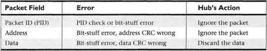
Corrupted Packets
There can be any number of different types of corrupted or missing packets. These include lost or corrupted tokens, data packets, or handshake packets. We talk about what all of these packets do, and describe their format, in Chapter 6. The accompanying table lists the possible packet errors that a hub should be equipped to detect, along with the expected response from the hub.
False End of Packet (EOP)
A false end of packet (EOP) is a phenomenon that occurs when a device detects the EOP marker before one actually exists. From a device’s point of view, a false EOP makes a single packet look like two separate packets. This has the potential to confuse a device.
The hub will handle a false end of packet differently, depending on whether the hub is being accessed directly or is acting as a repeater forwarding data to attached devices. When the hub is acting as a repeater, it does not attempt to understand the data flowing through it. If it doesn’t understand the data, then it cannot very well figure out whether the EOP is valid or invalid. In this case, a hub doesn’t see the error, so it ignores it.
The hub can detect a false EOP when it’s being talked to. If the hub detects a false end of packet, then the hub ignores all further traffic until the next start of packet (SOP). In this case, the hub manages false-EOP error-detection and recovery mechanisms just as any other USB device would.
Repeater-Fault Recovery
The hub must detect any condition that has the potential to cause the bus to wait “forever” or to be put into any state other than idle at the end of a packet transaction. If the hub does not catch these conditions, then the Universal Serial Bus, and all of the devices on it, will soon be in a confused and unreliable state.
Two of these conditions are defined by the USB specification: loss of activity (LOA) and babble. Loss of activity is defined as the detection of a start-of-packet token being followed by either no bus activity or no end-of-packet token before the end of the transmitted frame. Babble, on the other hand, is defined as bus activity continuing past the end of the frame. Because hubs have no notion of allocated bandwidth for isochronous devices, they must rely upon the frame timer to detect LOA and babble conditions. The hub will recover before the beginning of the next transmitted frame.
It’s important to note that the hub recovers only from faults originating in the upstream direction. It is up to the host to detect and recover from its own downstream errors. There are really only two hard-and-fast rules that a hub must follow:
1. A device that puts illegal data on the bus after the end of frame (babbles) must have its port disabled.
2. A hub must always ensure that the bus is in the idle state at the end of a bus transaction.
When there are no faults, these requirements are met by having the hub receive an EOP token with every packet and having no bus traffic occur past the end of a frame. This is normal bus operation. Under non-fault conditions, these requirements are met by virtue of a hub receiving an EOP with every packet and having no bus traffic occur past the end of a frame.
Power-Management Functions
Every hub must support the suspend and resume power-management functions. At the very least, a hub must propagate these signals downstream. There are two types of suspend and resume functions: global and selective.
Suspend and resume functions directed toward specific port on the hub are known as selective suspend and resume. Conversely, suspend and resume functions to be propagated through the root port are known as global suspend and resume. Global resume may be initiated either by the host or through the hub’s downstream port.
Global Suspend and Resume
Global suspend is implemented by causing the host to stop all downstream traffic to the entire Universal Serial Bus. When the root port on a hub is idle for more than 3 ms, then the hub goes into the suspended state. A suspended hub cleans up any pending bus transactions, maintains all per-port state and status, and preserves its own state and status. Since a suspended hub has its internal clock turned off, it has no concept of time. The hub can do nothing but watch the bus for transactions.
When the hub sees a transaction on the hub’s root port, then it puts itself into the resume state. This also occurs if any traffic is being initiated by an attached device. Further, the hub will exit the suspended state if a device is either attached to a port or removed from a port.
Selective Suspend and Resume
A selective suspend occurs when a single device or bus segment is put into a low-power state. This depends upon the ability of the hub to selectively suspend an individual port at the request of the host (with a PORT_SUSPEND request). A hub that can do this is called a disabling hub, though in practice almost every hub is a disabling hub.
As with the global suspend, a port that is suspended is prevented from moving any data downstream (except for a PORT_RESET request). Further, the only traffic that can be sent upstream is the port’s status, not any actual bus traffic from the device to the root port. The hub must ensure that a port is not put into the suspended state until any current bus transactions are completed. Rather than rejecting the suspend request from the host, the hub waits until the current packet is complete before suspending the port.
If there are ports further downstream of the port being put to sleep, it is only natural to assume that those ports will also be put into the suspended state. This is important behavior to note, since a device attached to a hub port may be another hub.
If a port on a hub is selectively suspended, but the hub itself is not suspended, then the hub must ensure that no traffic from the suspended port is reflected to the enabled ports on the hub. This reflection would have the potential of causing problems with the attached devices. Likewise, a resume message must be directed only to a specific port and not propagated to other suspended ports.
Hub-Reset Behavior
A fundamental function of a hub on the Universal Serial Bus is that it be able to respond to a host request that the hub reset itself. This is done, for example, when the host enumerates the devices on the bus. It must also be able to place any of its ports into the reset state, effectively resetting the device attached to that port. This section will talk about how the hub handles all this.
Hub Reset
A USB hub can be reset only by the host computer, or by resetting itself when it is first powered up. The hub is put into a default configuration when it resets. This default state includes the following properties:
![]() The hub controller default address is set to 0.
The hub controller default address is set to 0.
![]() The hub control bits are all set to power-up values.
The hub control bits are all set to power-up values.
![]() The hub repeater waits for an SOP.
The hub repeater waits for an SOP.
![]() On a powered switched hub, all downstream ports are placed in the powered-off state.
On a powered switched hub, all downstream ports are placed in the powered-off state.
![]() On a nonpowered switched hub, all downstream ports are placed in the disconnected state.
On a nonpowered switched hub, all downstream ports are placed in the disconnected state.
It should be noted that if a bus contains hubs that allow their ports to be power switched, then the host reset is not guaranteed to be sent all the way downstream to all devices. The host ensures that each level of USB devices, or tier, is reset when it goes through the bus-enumeration process (discussed in depth in the next chapter). Powered-off devices are reset. Self-powered devices and hubs reset both themselves and their downstream ports.
Per-Port Reset
The USB host can ask that a particular port on a hub be reset. It does this by issuing a PORT_RESET request to the hub. The port number of the downstream port is included as a part of this request. In order to reset the port, the hub signals the device on the port that it is being reset before setting the port itself to the reset state. A reset request is ignored if the port that is being reset is either powered off or disconnected.
Hub Power Distribution
A USB hub, by definition, supplies power to devices that attach to its downstream ports. This power is provided for bus-powered devices. The hub may be able to supply a variable amount of power to the downstream components. To facilitate the management of this, each device knows its power requirement and reports it to the host during the bus-enumeration process.
Hubs, like other USB devices, can be any combination of self-powered and bus-powered. For example, a hub may get power for its root-port operation from the bus while, at the same time, powering its downstream ports with an external power supply. An important restriction is that a hub can supply power only in the downstream direction (toward the devices) and never put power on the bus upstream. This keeps things electrically “sane.”
Every bus-powered hub has per-port power-switching capabilities on each of its downstream ports. Further, a bus-powered hub is required by the USB specification to power off all downstream ports when the hub first powers up. The hub is also required to power off all downstream ports when the host commands it reset.
As we discussed before, the host can cause power to be sent or withheld from a port under software control. While the bus-powered hub must have per-port power switching, it is acceptable to have the hub provide a single mechanism that switches power to all ports simultaneously.
It should be mentioned that a port-reset request does not affect the port’s power status. In addition, a hub port must be powered on before it can detect the attachment of a device.
Hub Endpoint Configuration
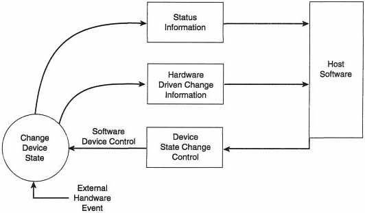
Every device must have an endpoint zero for configuration and status reporting, and a hub is certainly no exception. The hub communicates over its endpoint zero to tell the host when a device has been attached or removed. The host accesses endpoint zero through the default pipe. This endpoint uses what are called interrupt transfers. Periodically the host polls endpoint zero on the hub to find out if anything has changed on the hub. If there has been a change, then the hub sends data informing the host of the specifics of the change. If there is no change, then the hub merely returns a NAK (negative acknowledgement). Hubs are logically organized as shown in Figure 4–4.
Figure 4–4 Relationship of Status, Status Change, and Control to Device States
Port Changes
One of the most important functions the hub provides, apart from moving data from the attached devices to the host, is detecting changes in the state of each port it owns. Devices attached to the ports can cause any number of hardware events. The host software can also request that the hub change the state of any port (or the hub itself). Since the hub can be can be changed by either an attached device or the host software, then the hub will report any changes for either of the hardware-initiated events. The hub continuously reports a change until the host acknowledges it. This report could indicate any state change, such as a device being inserted or removed from the Universal Serial Bus. This approach keeps the state information that both the device and the host must maintain on each hub. The host software uses its default pipe and endpoint zero to detect these changes. (See Figure 4–4.)
The status of a particular port on a USB hub is requested by the host on a per-port basis. When the host has been made aware of any change, then it informs the hub of the fact and the hub clears the “change pending” flag in the port status register. This keeps the hub from reporting the port as being changed after the host sees the change, and ensures that the host will not be notified again—at least until the port status changes once again.
Hub Configuration
Hubs, like other devices, are configured through the standard USB device configuration commands, which are described in the next chapter. A hub that has not yet been configured behaves like all other devices that have not been configured—it does not provide power to downstream ports, and it responds only to the default address.
A hub is configured by the host software with a set of configuration commands. These configuration commands operate on the hub’s configuration descriptors. This is all done through the default pipe to endpoint zero. The host software will issue commands to the hub to put the hub’s ports into powered and powered-off modes at the appropriate times.
One important difference between the configuration of a hub and the configuration of any other USB device is that the hub provides power to other devices. The host examines the hub’s electrical characteristics and the power requirements of the attached devices to ensure that it will not violate the USB power topology.
Wrapping It Up
In this chapter we learned that a Universal Serial Bus hub is a fairly complex device. It maintains state on each connected device, as well as detecting misbehaving devices. It is the hub that ultimately drives the state of the attached devices, even if it is at the direction of the host computer.
It’s important to remember that a USB hub is nothing more than a USB device with a few special capabilities. Think of it as a “super” USB device. We’ll discuss the general case of devices in the next chapter. After reading this chapter, however, much of the next should seem very familiar to you.