
Chapter 5
Inside a USB Device
What Does a USB Device Do?
The first thing that you should understand about a Universal Serial Bus device is that nearly everything within a USB system is a device. The root hub is a device, as is every hub connected to the system. The peripherals that you attach to the Universal Serial Bus are all known as devices. The only part of a system that isn’t a USB device is the actual host controller (and the controlling system software).
Each USB device is divided into three distinct and individual layers. The bottommost layer is the part of the device that is responsible for communicating on the physical bus by sending and receiving packets. The next layer up is the protocol engine that is responsible for translating bus communications from the lowest layer and sending them to the topmost layer: the endpoint.
The topmost layer of a device is the device endpoint. The device endpoint is the part of the device that actually deals with the data that’s being sent around the bus. It uses information from the host, and it sends information to the host—every other piece of the device exists only to serve the device endpoint.
This chapter talks about the topmost layer of the device: the device endpoint. Certain attributes and operations are common to all device endpoints. The device in performing its defined functions uses all of these attributes and operation.
USB Device States
Before we can really begin to talk about what happens inside a device and why, it’s important to understand what different device states there are and how the device transitions between the various states. These states and transitions are what all of the device actions depend upon (e.g., a device can not send data if it’s in the powered-off state).
Each USB device has a finite number of states in which it can be. It can be in one (and only one) of those states at a time; i.e., states are mutually exclusive of one another. A USB device can also maintain a state apart from its USB state that is not visible to the host software (or other downstream devices) and is specific to its internal functionality. When we talk about state in this book, we’re dealing only with those defined states that are visible outside of the device. Internal states are device dependent and not a part of the Universal Serial Bus proper.
Figure 5–1 diagrams the various states and the transitions between them. It may appear complicated at first glance, but revisit it as you read the rest of this section and it should become clear. Like many things technical, it’s really much simpler than it looks.
Figure 5–1 Device-State Diagram
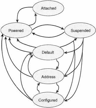
Six device states are defined by the USB specification. These are:
![]() Attached state
Attached state
![]() Powered state
Powered state
![]() Default state
Default state
![]() Address assigned state
Address assigned state
![]() Configured state
Configured state
![]() Suspended state
Suspended state
We’ll discuss each of these in depth in the following sections.
Attached State
Like most of the states, the attached state is named to convey exactly what it means. At any given time, a USB device connected to a bus either is attached to the Universal Serial Bus or is detached from it. Don’t confuse the attached state with whether or not a USB device is plugged into the bus. The attached state is a logical state that is only related to what the device and the host believe to be true, not what may be physically true. For example, a device need not be physically powered off for the host to consider it in the powered-off state. It will be in the powered-off state until the hub tells the host differently, not when the device is powered.
A device is put into the attached state by the host as part of the busenumeration process that we will talk about a little later on in this chapter. A USB device may be attached to or detached from the bus, but the USB specification only discusses what happens on a device when it is attached. If a device is detatched, then it should not be putting data on the bus (or, rather, the hub shouldn’t be allowing it too). From a USB perspective, we don’t care what the device does when it’s detached.
Powered State
The developers of USB devices must make an important decision: where to get the power for the device. If you recall from our earlier discussions, devices have the option to receive power directly from the Universal Serial Bus. Alternatively, each device can get its power from an external power source. In addition, as we will see a little later in this chapter, a device can offer the user the choice of using either bus power or external power.
Why would someone want to use external power when there’s “free” power on the bus? Take the example of a USB speaker. While you can certainly drive sound out of a speaker with the 5-volt, low-amperage power on the USB, you can drive “bigger and better” sound when using powered amplifiers. The same is true of the output from your sound card. The option is there because it can make sense for some devices.
The USB term for an externally powered USB device is self-powered. These devices may already be powered before the device and the host “know” that they’re powered—remember, these states are logical and only reflect what the device and the host agree on.
The USB terminology for a USB device that derives its power from the bus is, naturally enough, bus powered. Devices report how they are powered through an abstraction called the configuration descriptor, which we will talk about later in this chapter. The type of current power source is maintained as a part of the device’s current status.
Another thing that the device keeps track of in its configuration information is the maximum amount of power that the device can use. This is used by the USB host to decide if there’s enough power flowing across the bus to support the device. It’s also used to make proper decisions about what to do should there not be sufficient electrical current flowing around for everyone who wants it. An important note is that the device must observe this maximum, regardless of whether the device is drawing its power from the bus or from an external power supply. If the configuration supports only one source of power and the host software changes the source of the power (and this is legal), then the device will lose its current configuration and revert to the attached state.
Default State
While all of the states are relatively simple to understand, the default state is probably the easiest. The default state is achieved when the device first receives power. The device sits doing nothing until the host sends it a command to reset. After the host resets the device, then the device can be talked to, but only at the device’s default address. A better name for the default state might have been the “idle state.”
Address-Assigned State
When a USB device is being first configured, the host software addresses it through the use of its default address. One of the first things a host does, if you recall our discussion in Chapter 3, is assign a unique address to the device.
The device uses the default address at the time that it is first powered on. It also uses the default address any time the device receives a “reset” command from the host controller. Once assigned an address, the device remembers it, even if the device is put to sleep with a suspend command. The USB device only reverts to the default address if the device loses power, or a reset command comes from the host.
One thing you might want to remember in order to avoid confusion: the default address has nothing to do with the default pipe. The default pipe is used for configuration regardless of the address used for the device. We’ll talk about that later, as it’s not completely relevant to the discussion on device states.
Configured State
A logical thing to believe is that a USB device cannot be used until it is configured, that is, put into the configured state. As far as the device is concerned, the procedure to do this may be as trivial as writing something other than a “zero” to the device’s configuration register. It is up to the host software to set the configuration to something that the device can actually use. As you’ll see later, the device keeps a list of valid configurations from which the host can choose.
Setting a device to either its default configuration or one of the valid alternative configurations essentially causes the configuration of the device (and everything within the device) to revert to default values. This is important, because the host software must contain enough intelligence to “know” that it must reset whatever values it was using at the time it decided to change the state of the device.
Suspended State
As we’ve mentioned before, there is a limited amount of power on the bus. The host has to decide who’s using it and who can wait a while before using bus power. In addition, on a portable computer, the user may wish to suspend devices to conserve battery life. A device may also decide on its own, based upon certain criteria, that it wants to be a “friendly neighbor” to other devices it’s sharing power with and suspend itself. Regardless of the mechanism that puts the device there, the suspended state is the state the device enters when it stops draining power from its power source.
If a device is compliant with the Universal Serial Bus specification, then it will suspend itself if it has not detected activity on the bus for some given length of time. A device in the attached state can be suspended at any time after it has been powered up, regardless of whether it has been configured or assigned an address. A device will also enter the suspended state when something causes the hub port to which the device is attached to become disabled; this is a condition referred to as selective suspend. The host can also suspend itself after some period of no bus activity. This is certainly a valid way to put the all of the hub and devices on the bus to sleep.
To wake up a device (i.e., take it out of suspend mode), there simply needs to be bus activity to the device. Optionally—and we’re not going to explore this other than to say the capability exists—the device can send signaling over the Universal Serial Bus to request that the host exit the suspend mode. This capability is known as remote wakeup. It’s optional for developers of a USB device to provide for remote wakeup. Note, though, that if a USB device supports remote wakeup, then it must also provide configuration options to the host of disabling it.
Bus Enumeration
Bus enumeration is the process that the host uses to “map” the devices and topology of its Universal Serial Bus. This is not done just one time when the host is first powered on, as you might think. Rather, bus enumeration occurs each time that a USB device is either attached to or removed from the bus. This dynamic bus enumeration is called “hot plug.” The process is not really all that complicated and will be explained here.
First, let’s talk about what happens when a USB device is initially plugged into a Universal Serial Bus. Before the host can configure the device, it first has to know that a device has been attached. This detection happens when the hub that the device was plugged into tells the host that it has a new device. The hub is informed by means of some electrical signaling that occurs between the device and the hub (see the previous chapter for discussion on this).
It’s important to note that even if you plug a device directly into your computer, your computer has as a part of its hardware a root hub, which behaves just as any other hub. Likewise, hubs can be plugged into other hubs, in which case the host configures them just as any other device. We’re keeping our description here strictly generic in terms of USB devices. Hub-specific behavior is talked about in the previous chapter.
The hub tells the host that the USB device is attached by sending a message on a special pipe called the status-change pipe. At this point, the USB device is put into the attached state, and the port that it is plugged into on the hub is disabled. The host then consults its internal data structures and by talking to the hub determines exactly what changed. The hub tells the host that there is a new device, and tells the host the port number of the hub the device is living at.
Once the host knows where the new device lives on the bus, it tells the hub to enable the port that the device is attached to. The hub sends a “reset” command to that port, thus causing the newly attached device to reset itself to default values. At this point, the hub is also sending bus power to the USB device, causing the device to transition to the powered state. Since the device just experienced a reset, it answers only to the default address.
The host next asks the device about its capabilities (e.g., what’s the maximum amount of data it can send at a time). Once the host knows all of this information, it assigns a unique and currently unused address to the device. This causes the device to enter the addressed state.
The host next spends several bus transactions querying the newly attached device about its supported configurations. The client software on the host that is actually controlling how the device will be used decides which of the valid configuration options is best suited for this system. The host then assigns a valid configuration to the device. This, of course, causes the device to transition into the configured state.
Now that the device is in the configured state, its endpoints are available and ready to use. Also, the device can now begin drawing as much power from its power source as its configuration claimed it would draw. As far as the device is concerned, it is ready to use.
Device removal, in contrast with device attachment, is a relatively trivial operation. The hub, again, is the component responsible for telling the host that the device is gone from the bus. The host disables the port that the device was attached to. The host then updates its internal map of the bus to reflect the missing device. At this point, the unique address that the device was using is no longer valid and may be recycled and given to another newly attached device. Whether the host software actually reuses this address is completely up to that software and is not covered in either this book or the Universal Serial Bus specification.
USB Device Operations
The Universal Serial Bus supports a core set of operations for devices. These operations are common across USB implementations and must be supported by all devices. Before we can successfully delve into the form and function of the basic primitive operations that, in aggregate, make up higher-level operations, we should first address the functionality that we are attempting to achieve. We will delve into these high-level operations in this section.
Device Attachment and Removal
Devices on the Universal Serial Bus (and we include hubs among them) can be attached and removed from the bus at any time at the whim of the user. The hub that the device was plugged into, or is being plugged into, owns the responsibility of telling the host about the change. The host can then reconfigure its view of the bus—which is the only view that really matters.
Since the section on “Bus Enumeration” covered most of the specifics dealing with device insertion and detachment from the bus, we won’t spend a great amount of time and space discussing it here. There are a few points to make, however, before we leave this topic for another.
When a device is attached to a hub, the host enables the port on the hub where the device was detected. This has the intentional side effect of resetting the device. A USB device that has been reset conforms to the following set of characteristics:
![]() The device responds to its default address (and only its default address).
The device responds to its default address (and only its default address).
![]() The device is essentially unconfigured.
The device is essentially unconfigured.
![]() The device is not suspended.
The device is not suspended.
The host software works under these assumptions when performing whatever tasks it must in order to make the newly attached device a well-behaving citizen of the bus that it is attaching to.
When the host detects that a device has disappeared from the bus, it handles it in essentially the opposite manner—it disables the hub port where the device was attached. The host also cleans up the host software that was relying on the device. Whether the client software that was using the device cleans up nicely is entirely up to that software, and that behavior is not addressed by the Universal Serial Bus specification.
Again, the detail of events involved in the dynamic attachment and detachment of devices on the USB is described in the “Bus Enumeration” section of this chapter.
Address Assignment
Another of the primary high-level functions that the host must perform on a device is that of address assignment. When a USB device is first powered up and attached to the Universal Serial Bus, it responds only to the default address. It isn’t until the host assigns a unique address to the device that it can be used. The host performs this function as part of the bus-enumeration process. The address assignment occurs after the hub port where the device has been attached is enabled, or after a reset.
Configuration
Before a USB device can be used, it must be configured. It is entirely up to the host software (often in conjunction with the controlling client software) to configure the device. The host must first find out which configuration options the device supports before it can attempt to set any. This all seems like common sense, but you might be surprised to find out how many other computer buses don’t make this clear, and how many device-driver writers mess this up.
As you might well imagine, there are a quite a number of options that a device must be configured to support. We have already (in our discussion on device states) talked about bus-powered versus self-powered devices. This option is set by the host’s device-configuration process. The maximum data-packet size (the amount of data the device can send or receive at a time) for each of the device’s endpoints must also be configured.
A device might support multiple interfaces within a single configuration. A device interface is defined by the USB specification as “a related set of endpoints that present a single feature or function of the device to the host.” There may be a different protocol used to talk to each of these end-points within an interface. These may be specified by the device class and set as a part of the host’s configuration of the device. At the very least, a device will have one interface.
Each device may be capable of handling more than one configuration for a given interface (although not at the same time!). These alternate configurations can be chosen by the host at any point in the device’s existence on the USB. It is entirely up to the designer of the device as to whether or not multiple configurations can be supported. If alternate configurations are allowed, then extra effort must be made in designing the device (e.g., the “Get Interface” and “Set Interface” commands must be supported).
Every configuration on a device that supports alternate configurations has with it an associated interface descriptor. The interface descriptor associates an interface number with the alternate settings. The configuration setting that is in place when a device is initially configured is “alternate setting zero.”
Some device drivers are capable of managing a group of related USB devices. These are called adaptive device drivers. A single adaptive device driver might manage, for example, a dozen connected USB modem devices. In order to support these adaptive device drivers, each device and interface descriptor contains data fields for the device’s class, subclass, and supported protocol. These fields are used by the device driver to figure out what functions are provided by the attached device and which protocol should be used to communicate with those functions. The whole idea of class codes is discussed elsewhere in this book.
Device Requests
The host communicates with an attached USB device by issuing device requests to a pipe on the device. These requests are made using a mechanism called a control transfer. Each request is composed of both the actual request and the parameters that the request needs to complete. For example, a device request to change a device’s configuration must be made with a control transfer containing the request to change and the configuration to change to (the parameter). It is the duty of the host to establish the values of whatever parameters are transferred.
A control transfer on the Universal Serial Bus has a very specific format. While we will cover the formats of the bus traffic in the next chapter, we will delve here just a bit into what the packet involved in a control transfer looks like. It is known as a setup packet. It looks as shown in Figure 5–2.
Figure 5–2 Anatomy of a SETUP Packet

The host software initializes each of the data fields within the setup packet. Every setup packet is eight bytes long. The setup packet contains the following fields:
![]() The request type
The request type
![]() The actual request
The actual request
![]() The parameter value(s) and index
The parameter value(s) and index
![]() Data length
Data length
The request-type field is a bit-mapped field that identifies the characteristics of a given request. Bit-mapped means simply that each bit within the byte takes on a specific meaning; the meaning is not in the value of the byte as a whole. Specifically, the request-type field is used to set the direction for the data transfer that happens in the second part (or second phase) of the control transfer.
Following the request-type field is the actual request. Devices on the Universal Serial Bus respond to a standard set of device requests, and this occurs whether the device is configured or not. The valid standard requests are, quite simply:
![]() CLEAR_FEATURE
CLEAR_FEATURE
![]() GET_CONFIGURATION
GET_CONFIGURATION
![]() GET_DESCRIPTOR
GET_DESCRIPTOR
![]() GET_INTERFACE
GET_INTERFACE
![]() GET_STATUS
GET_STATUS
![]() SET_ADDRESS
SET_ADDRESS
![]() SET_CONFIGURATION
SET_CONFIGURATION
![]() SET_DESCRIPTOR
SET_DESCRIPTOR
![]() SET_FEATURE
SET_FEATURE
![]() SET_INTERFACE
SET_INTERFACE
![]() SYNCH_FRAME
SYNCH_FRAME
These requests will be elaborated on further along in this text. They are listed here to give you an idea of what is valid in the request field of the setup packet.
After the request field comes the nebulous value and index field. These values vary according to the request and are used to pass a parameter to the device. This parameter is entirely dependent upon the request.
The very last thing that you will find in a setup packet is the length. This is not the length of the setup packet but rather the number of bytes that are going to be transferred when the request is satisfied in the next transfer (or transfer phase).
While most of the requests seem self-explanatory, we want to say a few words about some that need comment.
Get_Descriptor
The GET_DESCRIPTOR request passed to a device supports three types of descriptors (keeping in mind that we’ll discuss descriptors at length in Chapter 7): device, configuration, and string. A request for a configuration descriptor causes the device to return the active configuration descriptor for the device, all interface descriptors, and all endpoint descriptors for each interface.
These descriptors are sent across the wire in groups associated by device interface. For instance, after the configuration descriptor is passed, the first interface descriptor is sent across the USB. Immediately following that, the first interface’s endpoint descriptors are sent. If there are additional interfaces in the device, then the sequence occurs again for each interface that is present in the device. All devices will provide at minimum a device descriptor and one configuration descriptor.
Get_Interface
The GET_INTERFACE request exists in order to get the currently selected alternate setting for a given interface. This is because many devices have interface configurations with mutually exclusive settings. The host has a very real need to understand the configuration for a given interface in this context.
Get_Status
The GET_STATUS request offers up a great amount of information about a given device. It returns information detailing whether a bus is currently self-powered or bus powered. It indicates whether a device is currently configured to allow remote wakeup requests (the default is not remote wakeup).
For each of the status items that a host can query, it can also set with a SET_CONFIGURATION request.
Set_Address
When the host wants to change the default address of a USB device to an address unique to that device, it issues a SET_ADDRESS request to the device. It can take up to three stages to set the device’s address. The first thing that happens is that a setup packet is sent to the device. The second stage is optional. In this stage, data may be transferred between the host and the device. The final, and not optional, stage is the transfer of status between the host and the device.
Status is sent to indicate the success or failure of the data stage. This means that status is always sent in the opposite direction of the data transfer. If there was no data transferred, then status is sent from the device to the host in acknowledgement of the SET_ADDRESS request.
It should be noted that the device does not actually change its address until after all three stages of the SET_ADDRESS request have completed. What this means is that all of the transactions making up the SET_ADDRESS request are directed to the same address (usually the default address); the data and status stages do not use the new address. This is different from other requests, where the request must be completely carried out before status is returned.
Sync_Frame
When an endpoint in a USB device supports isochronous transfers, the data that’s being sent may require that nonstandard frame sizes be sent (we’ll talk about this in much more detail in Chapter 7). These varying frame sizes will vary according to a specific pattern. The SYNC_FRAME request defines this pattern, as the host and the device must agree upon which frame begins the repeating pattern.
The SYNC_FRAME request causes the endpoint to begin watching the start-of-frame frame numbers to decide where the frame is in the pattern it is transmitting. Once the device decides which frame the pattern began in, that frame number is returned to the host. This is done only when the device is sending data patterns isochronously and the data is synchronized with the client software on the host (using pattern matching). If the device endpont is not isochronous, then this request is not supported and will be ignored by the device. Like other configuration options, this procedure will need to be repeated after a device reset.
Descriptors
Throughout this book we have been talking about descriptors without explaining exactly what they are. This section will explain descriptors in probably far more detail than you need. Follow it, though, and you’ll understand what descriptors are and why they are used.
Simply stated, a descriptor is nothing more than a well-defined data structure associated with some attributes on a device. The USB device reports its attributes using these descriptors.
Four basic types of descriptors are maintained by the USB device. These will all be explained a little later, but for reference they are:
![]() Device descriptors
Device descriptors
![]() Endpoint descriptors
Endpoint descriptors
![]() Configuration descriptors
Configuration descriptors
![]() Interface descriptors
Interface descriptors
Descriptors allow device attributes to be stored in data structures that look like something like database records. In this sense, different configurations within a device may reuse descriptors, or portions of descriptors, from configurations within the device that share characteristics.
Sometimes, descriptors need to convey string data (or human-readable text). Rather than storing this textual information on the device, a descriptor will reference text strings using an index number. This string reference is used by the client software to decide what the string text actually says. A USB device doesn’t have to support strings, but it does have to support the fields that reference them. If a device does not support strings, then the string reference is simply set to zero. The software on the host understands that a zero string reference means that there is no string available.
One thing common to all descriptors is that they start out with the length of the descriptor. If a descriptor returns with a value in its length field that is less than it should be, then the host will reject the descriptor as invalid. If the value in the length field of the descriptor is greater than what it should be, then the extra bytes are simply ignored.
Device Descriptor
Global information within a device, and used by all of the device’s configurations, is described in the device descriptor. Each USB device only has one device descriptor.
As we’ve discussed before, each USB device has an endpoint zero, and it’s used by the default pipe. The device provides the host with the maximum packet size that this endpoint will support. Other endpoints and interfaces are described in the configuration descriptor. There is no configuration descriptor for endpoint zero, and the maximum packet size is the only thing that a device can vary for a USB device. All other characteristics of endpoint zero are defined by the USB specification and are the same for all USB devices.
The device descriptor contains the following fields:
![]() Descriptor length
Descriptor length
![]() Descriptor type
Descriptor type
![]() Device-class code for the device
Device-class code for the device
![]() Device-subclass code for the device
Device-subclass code for the device
![]() Device protocol
Device protocol
![]() Maximum supported packet size
Maximum supported packet size
![]() Vendor ID
Vendor ID
![]() Product ID
Product ID
![]() Manufacturer string
Manufacturer string
![]() Product string
Product string
![]() Serial number
Serial number
![]() Number of supported configurations
Number of supported configurations
Configuration Descriptor
The configuration descriptor describes a device’s specific configuration. A field within the configuration descriptor, the configuration value, describes which of the available configurations is currently active on the device. The host sets the configuration value when it issues a SET_CONFIGURATION request to the device. This causes the device to assume the requested configuration.
The configuration descriptor also provides the number of interfaces provided by the selected configuration. As we’ve mentioned before, each interface may operate independently of any other. When the host asks for the device’s configuration descriptor, all of the related interface and endpoint descriptors are returned. For example, a combination stereo speaker and microphone may contain separate and independent interfaces for each speaker and the microphone.
A device can maintain multiple configuration descriptors, one for each interface and interface endpoint. Endpoints are not shared between the various interfaces within a single configuration. They may be shared, however, among interfaces that use different configurations.
Very little can be changed within a configuration once a device is put into it. Alternate configurations can be selected, essentially causing the device to be “reconfigured.” Beyond that, only the maximum packet size of an endpoint can be adjusted.
The fields of a configuration descriptor are as follows:
![]() Descriptor length
Descriptor length
![]() Descriptor type (configuration descriptor)
Descriptor type (configuration descriptor)
![]() Total length of the data returned for this configuration (including all of the interface and endpoint descriptors)
Total length of the data returned for this configuration (including all of the interface and endpoint descriptors)
![]() Number of interfaces
Number of interfaces
![]() Selected configuration value
Selected configuration value
![]() Configuration index (indexing a string describing this configuration)
Configuration index (indexing a string describing this configuration)
![]() Device attributes (e.g., bus- or self-powered, remote wake-up enabled)
Device attributes (e.g., bus- or self-powered, remote wake-up enabled)
![]() Maximum power consumption
Maximum power consumption
Interface Descriptor
The interface descriptor describes each interface within a given device on the Universal Serial Bus within the currently selected configuration. The interface descriptor for an interface is returned only when a device is satisfying a GET_CONFIGURATION request. Strange as it may seem, the interface descriptor cannot be accessed directly with a SET_DESCRIPTOR or GET_DESCRIPTOR request.
A configuration can contain one or more interfaces, each with its own set of endpoints. If this is the case, then each interface maintains a set of endpoint descriptors. If the active configuration supports multiple endpoints, then the endpoints for each interface are sent to the host immediately after the interface descriptor is sent when the device is satisfying a GET_CONFIGURATION request.
A device interface may allow its associated endpoint characteristics to be changed to alternate settings after the device has been initially configured. The default setting for an interface is alternate setting zero. These alternate settings can be put into place with SET_INTERFACE and GET_INTERFACE requests to the device. If an interface uses only endpoint zero, then it will not send any endpoint descriptors to the host. An interface descriptor never includes endpoint zero when it considers and tells the host the number of endpoints available.
The fields contained within an interface descriptor are:
![]() Descriptor length
Descriptor length
![]() Descriptor type (interface descriptor)
Descriptor type (interface descriptor)
![]() Interface number
Interface number
![]() Alternate setting
Alternate setting
![]() Number of endpoints
Number of endpoints
![]() Interface class
Interface class
![]() Interface subclass
Interface subclass
![]() Interface protocol
Interface protocol
![]() Interface string (rather, a string index describing the interface)
Interface string (rather, a string index describing the interface)
Endpoint Descriptor
Finally, we come to our last descriptor type: the endpoint descriptor. The endpoint descriptor provides information and configuration for each endpoint used in each interface. In fact, each endpoint used in an interface has its own descriptor. This descriptor contains all of the information that the host will need to calculate the bandwidth requirements of the endpoint.
Like the interface descriptor we just talked about, an endpoint descriptor cannot be directly manipulated or accessed with GET_DESCRIPTOR or SET_DESCRIPTOR requests from the host. Rather, it is returned as part of the configuration descriptor. Further, its capabilities can be adjusted only through a SET_CONFIGURATION request. As we’ve seen before, there is never an endpoint descriptor for endpoint zero.
The endpoint descriptor contains the following fields of information:
![]() Descriptor length
Descriptor length
![]() Descriptor type (endpoint descriptor)
Descriptor type (endpoint descriptor)
![]() Endpoint address (including the direction in which the endpoint transmits data)
Endpoint address (including the direction in which the endpoint transmits data)
![]() Endpoint attributes (i.e., control transfer, isochronous transfer, bulk transfer, interrupt transfer)
Endpoint attributes (i.e., control transfer, isochronous transfer, bulk transfer, interrupt transfer)
![]() Maximum packet size for the Endpont
Maximum packet size for the Endpont
![]() Polling interval (i.e., when should the host “poll” for information)
Polling interval (i.e., when should the host “poll” for information)
Device Communication
Having talked about device states, descriptors, and requests, we now discuss communication as a whole. Figure 5–3 illustrates how devices and the host communicate. In this section we focus on USB communication from the perspective of the device.
Figure 5–3 Device’s View of System Communication
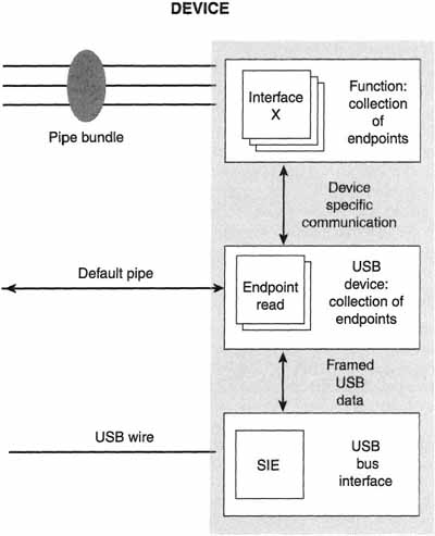
The bottommost “layer” of a device on the Universal Serial Bus is the USB bus interface. This bus interface provides the entire interaction between a device and the bus at an electrical and protocol layer. Above the bus-interface layer is the device-interface layer. The device-interface layer provides the interface between the device and the host. It is the layer that we will be talking about in this section. After all, the device’s function layer only uses capabilities provided by the device layer (combined as interfaces) to support the needs of the host client software.
In Chapter 3 we talked about what happens within the Universal Serial Bus host system. To refresh quickly, the host system contains a hardware controller called the host bus controller. The host controller drives all of the actual traffic on the Universal Serial Bus. Above the host controller lives the host controller driver (or HCD). The Universal Serial Bus driver handles all of the bus-specific functions in the USB system. The USBD has an interface that it exports to client programs. This interface is called the USBDI. Controlling each device, ultimately, is the client software on the host. That is a lot of different layers of hardware and software on the host. As you can see from Figure 5–3, each layer communicates with a corresponding layer on the device.
There are a number of layers on a USB device, but the relationships between them are implementation specific. While communication between the host and the device must occur across the USB physical wire, the logical source and destinations of communication happen between the various layers on the host and USB device. It is the host client software that is the ultimate consumer of the function provided by the device. The relationship between the client software and the device function drives all other interaction between the device and the host.
At its most base level, a device on the Universal Serial Bus is nothing more than a collection of endpoints. Each endpoint supports a given pipe. Finally, each pipe supports a type of transfer. If you recall, there are four types of transfers, but a pipe can provide support for only one type. What type of transfer a pipe can effect is decided at configuration time. The Universal Serial Bus transfer types are described in great detail in Chapter 6, and they are as follows:
![]() Control transfers
Control transfers
![]() Isochronous transfers
Isochronous transfers
![]() Interrupt transfers
Interrupt transfers
![]() Bulk transfers
Bulk transfers
An endpoint must behave in a certain fashion for each of these transfer types. While a pipe can support only one transfer type, an endpoint may support a variety of transfer types. That flexibility goes away, however, once an association is made between a pipe and an endpoint. After all, if the pipe that an endpoint is attached to can support only control transfers, then there is little chance that the endpoint will ever see traffic other than control transfers. We will assume, for the purposes of this discussion, that an endpoint that is being used for communication is associated with a pipe.
Four basic communication primitives, or mechanisms, are used in communicating with endpoints. These are:
![]() Pipe mode, either stream or message mode
Pipe mode, either stream or message mode
![]() Start-of-frame (SOF) synchronization, used to synchronize the device’s internal clock
Start-of-frame (SOF) synchronization, used to synchronize the device’s internal clock
![]() Handshaking, used to implement error detection
Handshaking, used to implement error detection
![]() Data toggle, used to implement flow control in isochronous applications
Data toggle, used to implement flow control in isochronous applications
We’ll cover these various communication mechanisms in depth in the sections that follow.
Pipe Mode
There are two modes that a pipe can support at any given time: stream mode and message mode. In stream mode, a pipe is considered to be a stream of data that flows in one direction. Message mode provides a bidirectional flow of bytes between the host and the device.
Stream-mode pipes always flow in one direction (i.e., are unidirectional). The receiving end of a stream pipe waits for a token indicating that data will be sent to it. The sending end of a stream-mode pipe, on the other hand, waits for a token asking it to send data. Data is always sent in chunks less than or equal to the maximum packet size specified in the pipe descriptor.
The host always initiates message-mode transfers. The host sends a command to the device, and then the device will send data to the host, or the host will send data to the device, or the command might require that no data change hands. In the case where no data packet is sent, a NULL data packet will be sent instead. It is the responsibility of the endpoint on the device to keep track of where it is in the context of the transmission sequence defined by the mode.
The first transaction in a message-mode transfer is a setup for subsequent communication. After the setup information is received by the endpoint on the device, the host will send to the endpoint a token indicating the direction of the transfer. If the device is to send data, it receives an IN token. If it is to receive data, it receives an OUT token. The setup command will determine the direction of subsequent transactions, even though some setup transactions do not require additional transactions to or from an endpoint.
Synchronization
Before the host and the device can communicate effectively, they must be synchronized with one another. To provide for this synchronization, the host sends out a start-of-frame (or SOF) token at a regularly timed periodic interval. This interval is 1 ms. Endpoints synchronize their internal clocks to this token. This enables each endpoint on a device to match its data transmission speed to that of the host. It also keeps both the host and the device from losing track of what data is being sent, since they both “look” for the data at the same point in time.
Not all endpoints in a USB device allow SOF synchronization, but they need to be synchronized nonetheless. These endpoints can force the entire Universal Serial Bus to synchronize to their internal clock, or they can attempt to adjust their transfer rate to compensate for the difference between the bus clock and their own clock.
The problem with attempting to have the bus adjust to the internal clock rate of an attached device is that there can be only one clock source on a given bus. If there is more than one device on the USB that cannot synchronize to the SOF packet, then something has to give. What happens in this case is that one of the devices becomes the “master clock” on the USB, and the other attempts to “adjust” to that clock rate. This is spelled out in the USB specification, but in the course of writing this book, the authors have not run across any devices that actually exhibit this restriction.
It is important to note that any device that cannot synchronize with the SOF packet must support both cases of either becoming the clock or adjusting. This is because there is no guarantee that it will be picked to provide the clock signal on the bus.
So, to sum up: three possible types of synchronization can occur for an endpoint with regard to the SOF synchronization. An endpoint can synchronize its clock with the USB clock, it can become the USB clock, or it can synchronize with the host by attempting to adjust its data flow.
Handshakes
Error and data-flow information is sent by the endpoints to the host by using handshakes. The host also may send handshakes to the device endpoint to inform the endpoint of an error condition. Handshakes are transfer-type dependent, and as such vary with the transport type used by the endpoint. This subject is covered extensively in Chapter 7.
Data Toggles
Sometimes when pipes are communicating, one or the other gets lost. This can occur because of an error on the bus or a simple flow-control problem. Some pipes are tolerant of this and are allowed to skip the frame that the error occurred in and resend the information during the next frame. In some cases, though, it is possible that the intended receiver thinks he received the data okay, but the sender knows better. In this case, the sender will attempt to retransmit the “lost” data. Unless the receiver knows that he is receiving the same data again, confusion can break out. Fortunately for us, the designers of the Universal Serial Bus considered this scenario.
The USB provides data toggles, which are packet IDs (PIDS) for the data phase of each transaction. Depending on the transfer type the endpoints are using, each endpoint needs to understand data toggles and handle the PIDs accordingly. Be patient, and refer to Chapter 7 for a complete discussion in the proper context of data toggles.
Wrapping It Up
This chapter has spent a lot of time talking about what happens inside a Universal Serial Bus device. Between this chapter and the two before it, you should be getting a pretty good feel for how the USB works. The only piece of the puzzle missing, from a Universal Serial Bus standpoint, is what happens “on the wire” with the USB protocols and transactions. We cover that in the next chapter.
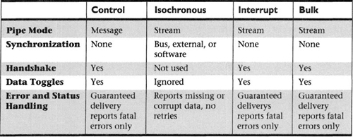
For your reference, the accompanying table summarizes the different modes and transfer types supported by USB devices.