CHAPTER 3
The Technology in the Standard
In this chapter, we provide an overview of the technology that has finally been standardized in MPEG-4. Let’s start with a description of the underlying trends that have initiated and shaped the technical content of the standard. These trends have induced a number of new application scenarios and service proposals dictating technical requirements that were subsequently transformed into an overall technical framework for MPEG-4. We will discuss the resulting overall architecture on a conceptual level to highlight how it is fundamentally different from existing coding standards in terms of the basic approach. Subsequently, we will give a comprehensive description of the individual technical constituents of MPEG-4. Emphasis will be put on the application and the benefit of the individual technological item. For a more detailed exposition of the technology, such as what might be requested by a developer or a frantic technology aficionado, we recommend you pick up one of the more technically oriented books on MPEG-4, a list of which is given in the reference list for this chapter. Finally, we will comment on few points where MPEG has been criticized.
3.1. The Trends Behind MPEG-4
Throughout the 1990s, there were a few general technological trends that had a strong influence on the MPEG-4 standardization. Knowledge of these trends is essential to gain an understanding of why MPEG-4 has evolved into the standard as it is known today. In particular, one must know about these trends in order to evaluate the content of the various comments on MPEG-4, either critical or positive, which have been published in articles and uttered in talks and presentations.
3.1.1. Better Compression for Audio-Visual Data
Besides all sorts of trends that were shaping the course of MPEG-4, perhaps the most common request was to devise coding technology for audio and video that provides significantly improved compression performance than previously known standards or products. There appears to be a certain rate (once a year?) at which startup companies around the world are issuing breaking news, such as that a new algorithm has been found by some formerly unknown genius, which can compress video 100 times better than all previously known technologies. The news is spread across the business sections of magazines and newspapers. But ultimately, most of those breakthroughs turn out to be not so breathtaking after all. The point is how much publicity a bold enough statement in this direction is likely to get. This is an indication of the yet unquenched thirst for better compression and the enormous business expectations that arise from having access to better compression. And it’s not just the startups; the established companies also are beating the drum of improved compression
As we will discuss in a later chapter, being able to pack digital media data more tightly is a fundamental capability that fuels a wide range of applications. A high level of compression provides significant cost savings and enables applications that would have been impossible before the compression technology was available. Take the impact that MP3 as a compressed audio file format had on the music business, since the advent of being able to download music over the Internet. The effect of increasing compression and increasing bandwidth is multiplying, strongly influencing the sheer number of new applications made possible by those technologies.
3.1.2. Object-Based Video Coding
For once, researchers in the field of video coding were intrigued by the idea of object-oriented video coding. This new approach promised to achieve better coding performance for video and image by segmenting video frames and images into meaningful objects, coding the individual objects more efficiently by overcoming the limitations of the more traditional approach of cutting an image into generic blocks of 8-by-8 pixels and coding those blocks. The video coding community had been attempting to overcome the limitations inherent in the more conventional approach by segmenting video frames and images generically into little square blocks and treating these blocks as the basic entity for coding. This traditional block-based approach had been employed in all the previous video and image coding standards, starting from H.261 all the way to MPEG-2 and also including JPEG. In contrast to the old block-based coding scheme, the new approach allowed for individual video objects that have an arbitrary shape, like the image you see when peeking through a key hole. In the decoding process, the video objects are decoded separately and glued back together to recreate the original video frames and images; that is, the scene shown in the image or video is recreated by composing the individual video objects to form the images and frames of the final presentation.
One of the more challenging research topics in this context is to actually find the meaningful objects in a video clip by means of segmentation. The segmentation problem has been and still is an active field of research. MPEG will not base a standard on technology that is not mature enough for prime-time applications. Since MPEG is not specifying the encoder, but only the decoder, solving the segmentation problem is of no major concern to MPEG. If in the coming years an ingenious researcher finds a smart algorithm with which to do video segmentation, i.e., to find the meaningful objects in a video automatically, there will already be a coding standard that can be used for building new products and services for transporting those objects to the consumers. In the meantime, it is possible to generate arbitrarily shaped video objects by means of blue-screen (or green-screen) production in the studios. As for the future of object-based video coding, the consumer’s decoder may already be prepared to digest those new object-based applications.
3.1.3. Natural and Synthetic Video
Visual media objects can be captured by conventional recording devices such as an analog or digital camera or other similar gear producing digital video signals or images in terms of waveforms or pixels. This type of material is denoted by the term “natural” video or images. Besides using cameras to shoot a movie or to take a picture, computers are increasingly being used to create visual media objects. This includes the computer-based creation of entire animated movies and images using the latest computer graphics technology. The extension of the traditional concept of pixel-based videos and images, which are captured by cameras to more general visual information as conveyed by computer generated images and animations is the reason why the term video that was used in MPEG-1 and 2 and other traditional standards has been replaced by the term “visual” in MPEG-4. In other words, traditional pixel-based video is merely one specific type of visual media object along with other types of synthetic visual objects, the other alternatives being discussed in more detail in the coming sections.
3.1.4. Natural and Synthetic Audio
A similar computer-based approach is taken for creating synthesized or computer-generated audio signals for music, as well as for speech. This is a way of producing audio that is comparable to taking a microphone to record music or speech. Computer-generated audio objects are referred to as “synthetic” audio. A similar situation to video also holds for the coding of digital audio information. Using a general audio codec like MP3 for the compression of speech signals is overkill. Being able to code different types of audio information with the appropriate codecs has clear benefits in terms of added functionality and improved coding performance. In the music recording business, it is commonplace to use synthetically generated sounds to create audio content. Samplers and synthesizers are standard tools in every music recording studio. This is further exemplified by the extensive use of MIDI, which stands for Musical Instruments Digital Interface. MIDI and synthesizers constitute basic ingredients of a more general framework that is concerned with the production of music using synthesizing tools.
3.1.5. Mixed Media
Yet another trend came about from the increasing use of mixed media presentation, which consists of different media types being combined to form an entire presentation. The mix may include video and audio along with graphics and animation, as well as text overlays using naturally captured imagery as well as synthetically generated images and sound. A good example of a mixed media presentation can be seen daily when watching Bloomberg Television or CNN, where stock tickers are scrolling across the screen, video clips are shown, and other information is inserted.
In traditional TV broadcasting today, there is already a heavy use of mixed media presentations in the form of graphical inserts, for example, which are overlaid on top of the video material. One particular aspect of this concept deserves a few more words here. In the situation described before, the composition of text and graphics together with video happens on the transmitter side. That is, the content is produced in the studio and the final composition of the presentation is completed at the TV station. The presentation to be broadcast is then sent to the transmitter, which comprises an MPEG-2 video and audio encoder for the compression and subsequent play-out of the TV broadcast.
Many people have made the observation that the visual quality of graphics and text overlays in digital TV broadcasts suffers quite severely from compression that uses image and video coding tools such as JPEG or MPEG-2 codecs. In order to satisfy the expectations of TV broadcast quality, a higher data rate is needed for the video compression task to achieve a faithful representation of text and graphics in a digital TV feed. A better and more economical solution can be achieved if the text and graphics elements are treated as separate media objects. Those text and graphics elements can be compressed with a specialized encoder optimized to handle this particular type of data. The compressed data representing the text and graphics portion of the media are transmitted as a separate data stream to the decoder. The decoder will decode those separate streams to reconstruct the visual appearance of the text and graphics element, which will then be glued on top of the decoded video. In contrast to the traditional way, where the material is generated and finalized at the TV station, this compositing process takes place in the receiving device, that is, in the set-top box or TV set. This approach produces better visual quality for the entire presentation because the quality of graphics and text is not suffering from being compressed by a video codec, while the total amount of bits to be transmitted is substantially reduced.
An ever increasing amount of media content consists of a mixture of various types of natural and synthetic media objects. From its use in the movie production business, we are quite acquainted with mixing graphics elements and more traditional film footage. This is a trend that everyone who goes to the movies can experience and witness, and which will gradually move down the media content food chain, finally ending up at the graphics pipeline of the user’s display device. Providing standardized ways to represent this mix in terms of units of audio, visual, or audio-visual content, called “media objects,” was considered by MPEG to fit those needs and also reinforce the new approaches that researchers were working on.
Mixing naturally recorded audio signals with synthesized sounds is a standard way of doing things in the music production business. Considering audio content as being composed of various natural and synthetic audio objects also makes possible the compression of individual constituents and the rendering of the final audio scene after decoding the audio objects. This is similar to the example discussed earlier for handling text and graphics overlay in the TV broadcast feed, the result being to achieve better audio quality using smaller amounts of data.
3.1.6. Interaction with Multimedia Content
The notion of interactive television has been a topic of discussion for quite some time, originating from the world of interactive computer games. This type of interactivity spurred the desire to manipulate video content similar to the way graphics images can be created and manipulated via the computer. This functionality is now typically referred to as content-based interactivity. Within MPEG-4, the term “content-based interactivity” has been coined, with far-reaching implications giving rise to a number of interesting applications. The most direct interactive application is one that supports the clicking on video objects in a presentation to initiate actions such as changing channels, which enables the user to shop or to access additional information about the object being clicked on. As an example of such additional data, consider a user who desires more information about a running back in a televised football game. By clicking on the player, a window pops up, displaying additional information about the player such as career yards in rushing, and his college and previous teams. The concept of interactive television has been heavily debated, and a whole collection of innovative ideas for such services are continuously kicked around.
3.1.7. Universal Access and Mobile Communications
As modern society becomes increasingly mobile, there is more and more of a demand to have universal access to data in general, and media data in particular. By universal access, we mean the capability to access media content almost anywhere on a wide range of mobile or stationary playback devices, via heterogeneous network connections including the Internet and mobile and wireless channels.
3.1.7.1. Error Robustness
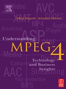
The vision of universal access necessitates the development of flexible schemes for representation of media data. But flexibility is not enough. If one thinks of the typical transmission characteristics associated with wireless transmission channels, it becomes clear that a data compression scheme must be rugged enough to protect against transmission errors. Even though channel coding techniques (error-correcting codes) that are part of the radio link can fix a substantial amount of transmission errors (that is, bit errors), a significant number of bit errors slip though undetected and uncorrected. The compression scheme that receives a compromised bit stream cannot decode the stream flawlessly and recreate the audio-visual presentation without impairments. However, the structure for representing the media objects and their composition can be designed in a way that the perceptible impairments are kept at a minimum, and the system can recover from corrupted data in a very short time frame. In other words, it is certainly not acceptable for a TV service to have the screen or parts of the screen go black for 30 seconds just because there have been some bit errors in the stream. However, if the failure to display the correct images and sound lasts for a split second and if the presentation is fine after that, then the service will be perceived as acceptable to consumers. Figure 3.1 shows an example of the difference error resilience tools can make in terms of visual appearance in case the bit stream carries transmission errors.
Figure 3.1 The effect of error resilience for digital video data
[Source: Iraj Sodagar, Packet Video].
3.1.7.2. Scalability
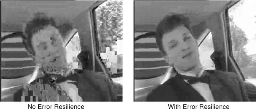
The notion of scalability serves as another ingredient to support universal access. Some types of scalability have already been addressed in the course of MPEG-2, where the plan was to code and broadcast a high-definition TV signal in such a way that a standard-definition TV receiver can extract a standard-definition TV signal, while a high-definition receiver can utilize the entire signal to produce higher quality images. This is referred to as spatial scalability (see Figure 3.2).
Figure 3.2 Spatial scalability
[Source: Touradj Ebrahimi, EPFL].
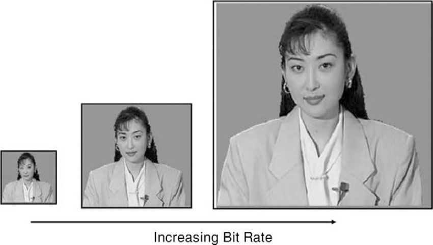
In addition to spatial scalability, there is the concept of SNR scalability (see Figure 3.3) in which the audio-visual signal is compressed in such a way that the receiver can decode parts of the stream in order to render images and sound at a quality level that varies with the transmission conditions. That is, if the transmission quality is bad, less bits of the presentation get delivered to the receiver. Instead of stopping, the receiver continues to play, though the quality is reduced. This type of operation is now fairly common when looking at videos that are streamed over the Internet. The abbreviation SNR stands for Signal-to-Noise Ratio and is a measure of the amount of noise or distortion in the signal in comparison to the undistorted signal. We will discuss such measures of quality in more detail in a later chapter.
Figure 3.3 SNR scalability
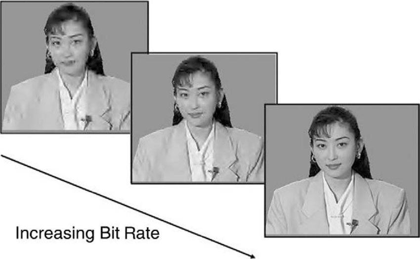
[Source: Touradj Ebrahimi, EPFL].
In the context of MPEG-4, there has been discussion about a new form of scalability that is object- or content-based. This type of scalability is about adapting the content to the transmission channel and device capabilities by selecting the media elements or media objects that constitute the content deemed to be more important or more interesting to the user, and dropping the other elements from being transmitted altogether. This kind of scalability requires the object-based coding approach.
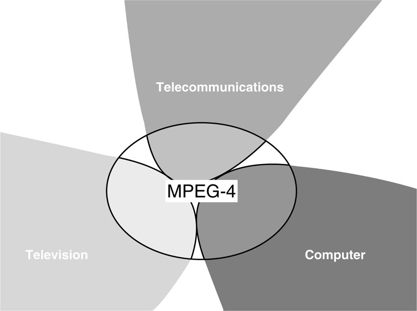
3.1.8. Convergence—Computers, Television, Telecommunications
The trends that fueled the MPEG-4 standardization process are based on concepts and notions that originated from three different industries and application domains—computers, television, and telecommunications. In the 1990s, this was commonly referred to as the convergence phenomenon. While the business models in these three domains may remain separate for a little longer, they already share much of their underlying technology. The convergence phenomenon can be understood as the combination of different technological approaches, which have evolved separately in the three domains and are now about to be fused to build a new technological basis for all three. Following this paragraph, you will find a partial list of concepts that the respective domains brought to the table, which are now combined in the MPEG-4 standard.
• Computer Industry: Computer games, Internet, interactivity, best-effort, download, software, IP protocols
• Television Industry: Entertainment, movies and television, consumer electronics, (Post-) production studios, broadcasting, satellite, terrestrial, cable, guaranteed QoS (quality of service), hardware
• Telecommunications Industry: Communications, wireless channels, bi-directional communication, back-channel, guaranteed QoS, universal access, mobility, ISDN, DSL, switched-circuit networks
3.2. Roles
The concepts underlying MPEG-4 also take into account the different roles one finds in the food chain of the digital media business—content authors, network service providers, and consumers. This section summarizes the various roles and their contribution to MPEG-4.
Figure 3.4 Convergence of major industries.
3.2.1. Content Authors
For content authors, it is commercially valuable to produce content that can be used more than once, i.e., it can be distributed several times via different digital transmission channels and consumed by end users on a wide range of different display devices ranging from set-top boxes via PCs all the way to mobile receivers. To this end, the digital content requires a representation that offers a level of flexibility that is not yet available today. Digital television, animated graphics, World Wide Web (WWW) pages and their extensions all use individual and non-interoperable technologies. The list of target display devices includes TV sets, computers, laptops, and portable media players, to name just a few alternatives. The content needs to be adapted specifically for each of these distribution channels and display devices. New exploitation channels, such as multimedia messaging services via wireless channels aiming at cell phones and PDAs, need yet another round of adaptation. Media produced for a traditional TV broadcast cannot be displayed on a handheld device without an appropriate modification or re-formatting of the content. The mobile transmission channel does not offer sufficient bandwidth to carry the broadband TV broadcast and, moreover, the mobile playback device is much too feeble in terms of its memory size and computational capabilities to render the full screen images in real time. Rendering low-resolution content on a TV screen is technically less challenging, but very disappointing from the user’s perspective and thus unsatisfactory.
Authors who are searching for ways to exploit their creations in a cross-media approach need to create or re-create their content multiple times to adapt it for each of the various channels and playback devices. For such a cross-media approach, it is clearly beneficial for the content to be represented in a very flexible way that allows for an easy adaptation and conversion so the content will match the capabilities of the delivery mechanisms (transmission channels) and the playback device. If the content can be published in one generic format from which almost any type of exploitation scheme can be fed, then content management is made easier and longevity and cross-media exploitation of the content is also feasible. Furthermore, the longevity of a particular digital representation is also an important feature in order to justify the investment in creating a pool of digital media.
3.2.2. Network or Service Providers
The previous arguments also apply to the group of network service providers, where the need to maintain and manage a wide selection of differently formatted versions of a particular media content is a financial and organizational burden. Alternative to this, it is beneficial for the service provider to store and process only one generic source for the content, which can be sent out via its network after adapting the material appropriately for the delivery. If the content format allows for transparent hinting information to indicate which part of the media is more important for the presentation and which Quality of Service (QoS) parameters it requires, then this information can be interpreted and translated into the appropriate native signaling messages for each of the networks. Signaling of the desired media QoS end-to-end enables transport optimization in heterogeneous networks; the transmission mechanisms can be exploited and configured to keep the cost at a reasonable level for a certain type of service offering. If there are bits carrying media services, then they need to be transmitted and delivered to the customer. The transmission requires bandwidth, which costs money. Bringing more programs to the customers and delivering a better product in terms of image and audio quality at a given bandwidth, and hence for fixed costs, represent major objectives for service providers that have a strong influence on their profitability. Therefore, developing new compression technology to further improve coding efficiency or to increase the capabilities for compressing any type of media data is of prime importance to network service providers.
3.2.3. End Users—Consumers
It is not so hard to make a user or consumer of multimedia content happy, but the difficulty of turning him or her into a paying customer varies largely depending on the particular market segment. The value network for TV consumers is well known and has been handled for quite some time now. Let’s have a look at what a media consumer may want in the current setting of the information age, bringing data networks and mobile communication infrastructure into multimedia delivery channels.
The role for the user is relatively easy to describe. Users appreciate a problem-free reception and the convenient, universal access to interesting and attractive media content that comes in high quality in combination with a wide range of choices. The appropriateness of the price tag that comes with consuming multimedia content is perceived differently, depending on the scenario. While many consumers, in particular the infamous couch potatoes, have no problem spending the money to have access to cable TV, for example, in the United States, it has been more difficult to establish the notion of paying for content when it comes to multimedia over the Internet. This aspect of different perceptions of value is beyond the scope of this book and may be covered elsewhere.
MPEG-4 brings brighter images and pictures to consumers, crystal-clear multi-channel sound, computer graphics and animations, or a mix of all these plus an entirely new interactive experience; that is, MPEG-4 enables the implementation of functionalities to achieve higher levels of interaction with the content. The quality and the amount of interaction offered to the user are designed by the author. This may range from no interaction at all up to full interaction, comparable to the experience of playing computer games. Even some new and innovative ways of interaction are anticipated and supported by MPEG-4. It also brings multimedia to new networks, including those employing relatively low bit rates, and mobile networks as well. For the end user, the type of underlying transport mechanism is not a concern since it is expected to be transparent. MPEG-4 allows the deployment of intelligent networks that include the capability to adapt the content to the target device in a smart way, which may be completely transparent to the end user. This means that a broadcast can be received simultaneously on totally different devices delivered via completely heterogeneous networks.
It is the task of content authors to design multimedia content that is considered to be interesting and attractive. In fact, it needs to be attractive enough to make people want to pay for it. In that sense, attractive content may include new functionalities and features, such as interactivity or various levels of personalization. It is the task of technologists to provide the tools, technologies, and products to create, format, and publish such content. Furthermore, the products in the hands of a consumer need make the access to and use of the potentially interactive and personalized content easy and seamless, while offering a premium product, in terms of the experienced visual and audio quality. However, there may be new applications that can get away with providing an inferior audio and video quality as long as the offered additional functionality is interesting. It is generally held that the overall service or product quality must offer added value to the end user in order to convince him to pay for the consumed content. In this sense, user satisfaction and added value are the ingredients that make new business models in the media world feasible and profitable. Better quality is one way of achieving added value, but there is certainly a limit for quality beyond which it doesn’t make economic sense to push the envelope. Creating an entirely new user experience is a feasible alternative, at least from a technical point of view.
Improved convenience, ease of use, and attractive pricing are aspects that can be supported by standardized technology. In summary, for all those parties involved—that is, for authors, service providers, and consumers—MPEG-4 seeks to create a widely acceptable and open technological framework in order to avoid the existence of a multitude of proprietary, non-interworking formats and players. This also has a number of business-related benefits to reduce the risk of investing in technology. This is discussed in more detail in the chapter on business aspects of MPEG-4.
3.3. The Architecture of an MPEG-4 Terminal
As discussed in the previous section, the three major trends—audio-visual media over all networks to all displays, accounting for increased mobility of users, and a growing level of interactivity—have driven, and still drive, the development of the MPEG-4 standard. To address these identified trends in an integrated and comprehensive way, a media coding standard is needed that includes the means to efficiently represent all sorts of different media data types. The supported bit rates and the required visual quality levels necessitate a representation of visual data starting from very low bit rates and low video resolutions up to very high video quality and resolutions, to cover the range of videos to be watched on hand-held devices all the way to enjoying movies in a digital cinema. Music and speech data need to be represented for a very wide bit-rate range as well, supporting everything from transparent music (also known as CD-quality) down to very low bit rates for intelligible speech, the sound of which evokes memories of speaking robots in science fiction movies. In addition, the standard includes tools to deal with 3-D graphical objects and images as well as other specific visual objects such as human faces and bodies and their animation.
3.3.1. Coded Representation of Media Objects
The overall architecture of a complete MPEG-4 terminal is depicted in Figure 3.5. In the context of MPEG-4, audio-visual scenes are considered to consist of a collection of several audio-visual objects, natural as well as synthetic, which are composited to form the final presentation. The objects are temporally and spatially placed in the scene. The individual audio-visual objects have a coded representation, where the underlying best possible coding approach is selected for the given object type. This approach achieves the best possible compression performance for the individual media objects.
Figure 3.5 Overall architecture of MPEG-4.
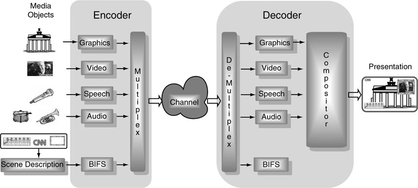
MPEG-4 standardizes the coded representation for a number of such primitive media objects. In addition to more traditional audiovisual media objects, MPEG-4 also defines the coded representation of objects such as text and graphics, talking synthetic heads, and associated text used to synthesize the speech and animate the head, as well as synthetic sound.
A media object in its coded form consists of descriptive data elements that allow the handling of the object in an audio-visual scene. The object may also consist of associated streaming data. It is important to note that in its coded form, each media object can be represented independent of its surroundings or background.
The coded representation of media objects is as efficient as possible in terms of the number of bits needed, while taking into account further desired functionalities. Examples of such further functionalities are error robustness, easy extraction and editing of an object, or having an object available in a scalable form.
The various objects in the scene are represented independently, allowing independent access to the objects in order to enable their manipulation and re-use in a different context. Interaction and hyperlinking capabilities can be assigned to individual objects, as well as the capabilities to manage and protect intellectual property on audio-visual content and algorithms, such that only authorized users have access. The representation format is independent from the actual delivery media, so as to transparently cross the borders of different delivery environments. In other words, the principles for the coded representation of media objects are independent to the way the content is delivered. Prominent choices for the transmission media are satellite transmission, cable, terrestrial broadcast, IP networks (Internet), mobile communications, ISDN, WLAN, and the like.
3.3.2. Composition of Media Objects
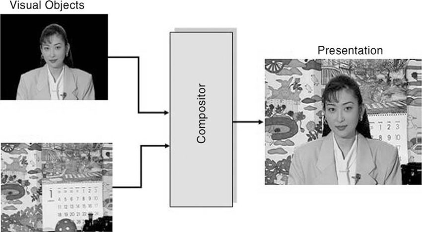
Besides the data for the individual objects, which determine the players in a scene, additional information on how those objects are supposed to be composed is needed to render the final presentation. The composition of media objects (objects and frames) illustrates the way in which an audio-visual scene in MPEG-4 is made up of individual objects. The composition information forms a separate data entity, which must be created, compressed, and transmitted to the receiver. The receiver gets the data streams carrying the coded data for all the objects and for the composition information and builds the scene on the screen through a rendering process. Figure 3.6 shows a very simple example of a presentation that is composed of two video objects, a background image and a foreground object.
Figure 3.6 Composition of video objects to form a presentation.
The composition information is structured in a hierarchical fashion, which allows media objects to be constructed of smaller media objects in a recursive way. The hierarchical structure can be best depicted graphically as a tree. The leaves of the tree represent primitive media objects, such as a still image (for the fixed background in the scene), arbitrarily shaped video objects (e.g., showing a talking person without the background), and audio objects (e.g., for the voice associated with the person in the video object) or primitive graphical objects such as rectangles, square, or circles. While primitive media objects correspond to leaves in the descriptive tree, compound media objects encompass entire sub-trees. A sub-tree is a part of a tree structure that itself exhibits the properties of a tree. (See Figures 3.7 and 3.8.)
Figure 3.7 A scene composed of different media objects
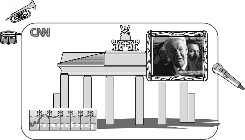
[Source: Carstin Herpel, Thomson Multimedia].
Figure 3.8 A graph representation for the scene in Figure 3.7 with the primitive media objects at the leaves of the scene tree. A very readable article on scene graphs can be found at
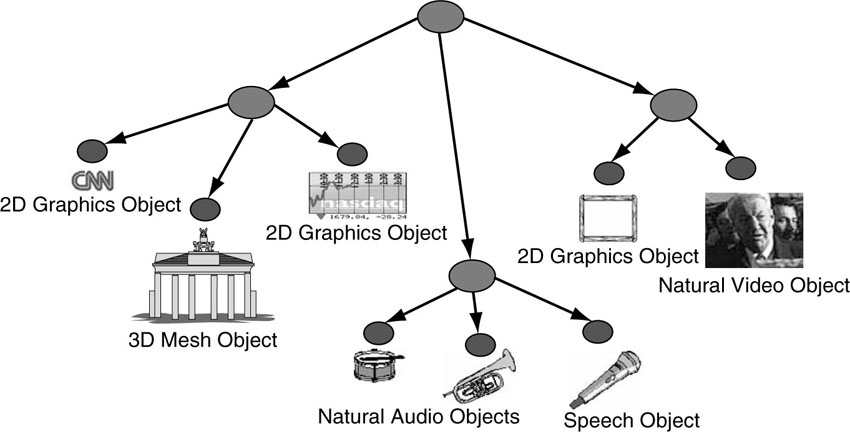
[Source: A. E. Walsh, Dr. Dobb’s Journal].
The scene description builds on several concepts from the Virtual Reality Modeling Language (VRML) in terms of both its structure and the functionality of object composition nodes, and extends it to fully enable the aforementioned features.
3.4. MPEG-4 Comes in Several Parts
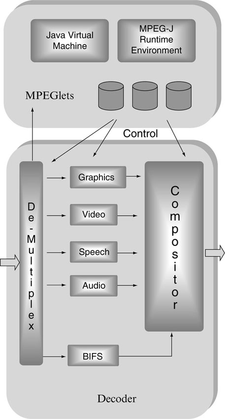
The standard is divided into several parts. Each part covers a certain aspect of the whole specification. Figure 3.9 offers an overview of where the major technical parts of the MPEG-4 standard are located.
Figure 3.9 Overview of the parts of the MPEG-4 standard and their functional locations in a standard decoder.
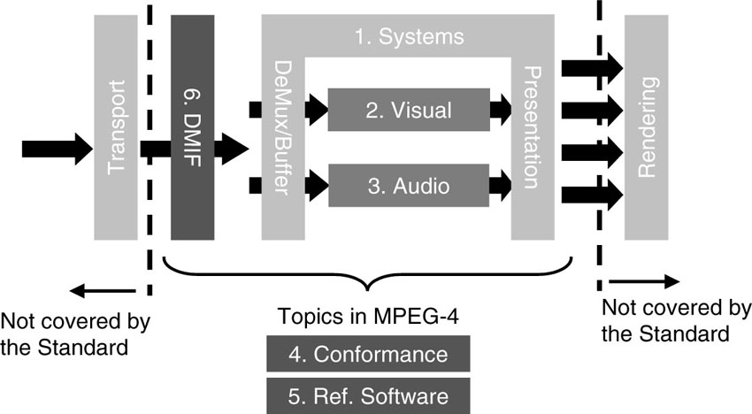
All parts have been designed and tested to work when taken together as components of a system. However, it is also possible to select individual parts of the specification in combination with other technologies for building products and systems. While the various MPEG-4 parts are rather independent and thus can be used by themselves, as well as combined with proprietary technologies, they were developed so that the maximum benefit results when they are used together.
3.4.1. ISO/IEC 14496-1—Systems
The systems portion of MPEG-4 (Part 1) contains the specification for the composition information for the scene, commonly referred to as the scene description. Part 1 also deals with multiplexing multiple data streams into one serial data stream carrying all necessary data for an audio-visual presentation. Furthermore, Part 1 also handles the synchronization of multiple data streams; for example, the video and the audio streams for a clip need to be aligned in time to achieve lip sync. The same applies in a multi-user scenario such as videoconferencing or multi-player gaming if there are multiple data streams coming in that have an influence on the actual look of an audio-visual presentation.
Buffer management is yet another topic, which comprises the task of managing the amount of data coming into a receiver device and the storage and handling of those streams in terms of available and necessary memory space. Running out of memory will lead to data loss and interrupted service. For content owners, it has become increasingly important to keep control over the media data and their usage. MPEG-4 Part 1 specifies tools for the management and the protection of intellectual property rights.
3.4.1.1. Object Composition—Scene Description
MPEG-4 Systems (or Part 1) provides the object composition technology referred to above. This is based on VRML but provides extensions to it by allowing the inclusion of streamed audio and video, natural objects, generalized URL, and composition updates. As VRML is a text-based language, it is easy to read and understand. However, the resulting amount of data for a complex 3D-graphics world can be overwhelming for streaming and online services. For this reason, MPEG has worked on a modification of VRML to achieve a binary version with very effective compression for VRML-type information. This modified version is called BIFS, which stands for Binary Format for Scene Description, and is a highly compressed format taking 10 to 15 times less data then a corresponding VRML-based scene description. The compression of scene description data, the capability to stream the scene descriptions and modify them dynamically, along with the addition of features that are useful for TV services and broadcast, are the main additions of MPEG BIFS that distinguish it from VRML.
The concept of streamability means that a scene being described can be used at the receiver side even before the entire scene description data has been downloaded. At the same time, MPEG has defined means to modify scene descriptions that already reside at the user’s terminal. Thus it has become feasible to start offering live services or to implement remote interactivity via a backchannel (network gaming). For VRML worlds, the entire scene description needs to be downloaded completely before any interaction with the content can start. MPEG-4 BIFS contains a number of extra features that make it a binary superset of VRML. For example, VRML only addresses 3D worlds. MPEG-4 will be used in some applications where there is only a need for 2D graphics in combination with other natural video objects. Therefore, BIFS defines 2D nodes that are needed by 2D-only applications for reasons of higher efficiency and lower complexity. MPEG-4 also supports a powerful and flexible audio-processing sub-tree capable of generating from simple up to true 3D audio environments.
3.4.1.2. Interaction with Media Objects
In general, the user observes a scene that is composed according to the design of the scene’s author. Depending on the degree of freedom designated by the author, however, the user may potentially interact with the scene. Operations a user may be allowed to perform include changing the viewing/listening point by navigation through a scene, or dragging objects in the scene to different positions, or triggering a cascade of events by clicking on a specific object, e.g., starting or stopping a video stream, or selecting the desired language when multiple language tracks are available. More complex kinds of behavior can also be triggered, e.g., a virtual phone rings, the user answers, and a communication link is established.
Interactivity is supported by the architecture of BIFS. Hierarchical groupings of objects allow for authors to construct complex scenes, and enable consumers to manipulate meaningful sets of objects. MPEG-4 BIFS provides a standardized way to describe a scene so that, for example, media objects can be dynamically placed and moved anywhere in a given coordinate system; transformations can be applied to change the geometrical or acoustical aspect of a media object; primitive media objects can be grouped in order to form compound media objects; streamed data can be applied to media objects in order to modify their attributes (e.g., a sound, a moving texture belonging to an object, animation parameters driving a synthetic face); and the user’s viewing and listening points can interactively be changed anywhere in the scene.
3.4.1.3. eXtensible MPEG-4 Textual Format (XMT)
XMT is a framework for representing MPEG-4 scene descriptions using a textual syntax. In a way, this seems like a step backward from BIFS. It is true that XMT does not provide the same level of bit-efficient representation as BIFS. However, since BIFS is a binary format and highly compressed, it is very suitable for transmission and storage, but it is not easily accessible to human readers. For content authors, it is important to understand the intentions and the meanings of media objects and their interaction, especially if the design is to be shared and exchanged between several designers. This was one of the major motivations behind defining XMT. One could think of BIFS as a “compiled” version of XMT. With this image in mind, it is easy to understand the usefulness of XMT, since scientists in other disciplines, for example, exchange ideas and algorithms by means of looking at source code instead of trying to decipher compiled machine language code. XMT allows the content authors to exchange their content with other authors, tools, or service providers, and facilitates interoperability with both the Extensible 3D Format (X3D) being developed by the Web3D Consortium (the new name of the VRML Consortium), and the Synchronized Multimedia Integration Language (SMIL) from the W3C consortium. XMT builds on top of proven concepts and architectures from XML (eXtensible Markup Language), which can be regarded as a sophisticated evolution of html.
Figure 3.10 Interactive content
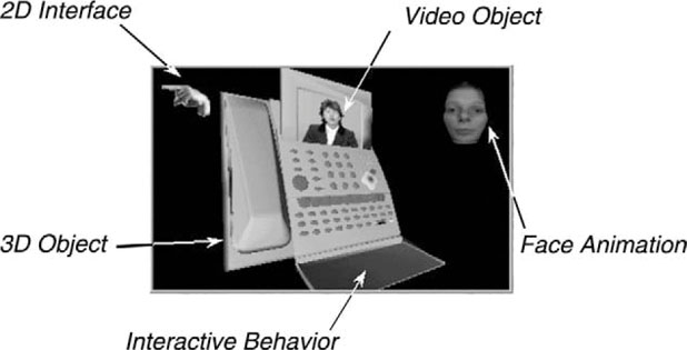
[Source: Julien Signis, France Telecom].
Figure 3.11 Schematic representation of XMT as a link between different formats for media data types
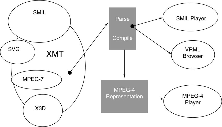
[Source: MPEG-4 Overview].
3.4.1.4. Stream Synchronization
Precise synchronization of audio and video objects is an important feature that builds on features similar to MPEG-1 and MPEG-2. MPEG-4 Systems supports both push and pull delivery of content. MPEG-4 also supports Object Content Identification (OCI) so that searches in databases of MPEG-4 objects are possible. To accommodate the needs of content rights holders, each MPEG-4 audio, visual, and audio-visual object can be identified by a registration number similar to the well-established International Standard Recording Code (ISRC) of Compact Disc Audio. Synchronization of elementary streams is achieved through time stamping of individual distinct units within elementary streams. Distinct units of a bit stream, which are somewhat self-contained and can be directly accessed in an independent way, are called “access units.” An individual frame in a conventional video clip can be considered as an access unit. The synchronization layer manages the identification of such access units and their time stamping. Independent of the media type, the synchronization layer allows identification of the type of access unit (e.g., video or audio frames, scene description commands) in elementary streams, recovery of the media object’s or scene description’s time base, and it enables synchronization among the various media objects and the corresponding scene description. The syntax of this layer is configurable in a large number of ways, allowing use in a broad spectrum of systems.
3.4.1.5. Digital Rights Management
Another important feature of the Systems part of MPEG-4 is the so-called Intellectual Property Management and Protection (IPMP). IPMP consists of a number of specified interfaces to an MPEG-4 system to support the possibility of plugging in proprietary technologies to manage and protect content. MPEG has refrained from specifying Digital Rights Management (DRM) systems or standardizing watermarking technology. It is commonly believed among MPEG delegates that content protection systems lie outside of the MPEG standard. Such systems deploy encryption of the content and embedded IP (Intellectual Property) information.
However, it is necessary to provide hooks and interfaces and some elementary mechanisms that allow a service provider or content owner to select a state-of-the-art and potentially proprietary system for digital rights management offered by a third party to take care of protecting the content via watermarking or whatever. This way, MPEG-4 enables the use of DRM systems that manage and protect intellectual property, similar to conditional access systems used for pay-TV services.
It is vital to be able to identify intellectual property in MPEG-4 media objects. To that end, MPEG has worked with representatives of different creative industries in the definition of syntax and tools to support this. MPEG-4 incorporates identification of intellectual property by storing unique identifiers that are issued by international numbering systems (e.g., ISAN, ISRC, etc.1). These numbers can be applied to identify a current rights holder of a media object. Since not all content is identified by such a number, MPEG-4 enables intellectual property to be identified by a key-value pair. Also, MPEG-4 offers a standardized interface, which is integrated tightly into the Systems layer, for people who want to use systems that control access to intellectual property. With this interface, proprietary control systems can be easily amalgamated with the standardized part of the decoder.
3.4.1.6. MPEG-J
MPEG-J is a programmatic system that specifies application programming interfaces (APIs) for interoperation of MPEG-4 media players with Java code. The programmatic approach contrasts with the parametric approach offered by the rest of the MPEG-4 system. Using MPEG-J, it is possible to execute Java applets (MPEGlets) that add richer behavior to MPEG-4 content, and to provide interfaces to network and terminal resources. The term ‘richer behavior’ is often meant that the terminal can support operations that are more complex and feature rich than simply pressing buttons for pausing, rewind, or continue. This approach is schematically depicted in Figure 3.12, where a decoder terminal is shown that receives MPEGlets, which can then be used to control resources in the decoder terminal. To accomplish this, a Java Virtual Machine and a Java Runtime Environment must be present.
Figure 3.12 The marriage of MPEG and Java produces MPEG-J.
3.4.1.7. ISO/IEC 14496-14—MP4 File Format
For the reliable exchange of complete files of MPEG-4 content, the file format “mp4” has been specified. The mp4 file format has been developed based on Apple’s QuickTime file format, with its technical features extended. A file format that facilitates interchange, management, editing, and presentation of media information of an MPEG-4 scene in a flexible and extensible format is an important addition to the MPEG-4 Systems tools. This is provided by the mp4 file format. The presentation may be “local” to the system, or may be via a network or other stream delivery mechanism. The file format is independent of any particular delivery protocol, while enabling efficient support for delivery in general.
3.4.2. ISO/IEC 14496-2—Visual
Part 2, the visual part of MPEG-4, specifies the coded representation of natural and synthetic visual objects. In MPEG-1 and MPEG-2, the corresponding part used to be called “video.” Since MPEG-4 has extended its scope far beyond the traditional notion of video to support a wide variety of types of visual information such as graphics or still images, the name of this part of the standard has been changed to “visual.”
3.4.2.1. Compression of Natural Video
MPEG-4 Visual provides video coding algorithms for the compression of natural video that is capable of coding video at very low bit rates, starting from 5 kbit/s with a spatial resolution of QCIF (144×176 pixels) up to bit rates of some Mbit/s for standard television resolution video (Recommendation ITU-R 601). On the upper end of the quality scale and bit rate range are coding tools combined in the Studio Profile, which supports bit rates of over 1 Gbit/s. In addition, MPEG-4 offers a Fine Granularity Scalability mode that allows for transmission of the same video content at different bit rates (SNR scalability). This wide range of bit rates and supported features is the result of specifying MPEG-4 Visual as a true box of video coding tools, according to the established principle—one functionality; one tool. The tools can be selected individually and combined to specify a terminal that satisfies the needs of a particular application domain. In order to prevent the possibility of too many incompatible terminals, MPEG includes a number of preset configurations of its video coding tools. Such a preset is called a “Profile.” The concept of a profile is not restricted to the visual part of the standard, but applies to MPEG in general. The underlying principle for profiles will be discussed in a later chapter. Profiles were initially designed to match the requirements of prototypical application scenarios, which were conceivable by the time the specification was done.
One important feature of MPEG Visual is the ability to code not just a rectangular array of pixels, but also the video objects in a scene, where the object may have an arbitrary shape. An object can be a walking person or a running car or the ball on the foot of a soccer player.
3.4.2.2. ISO/IEC 14496-10—Advanced Video Coding (AVC)
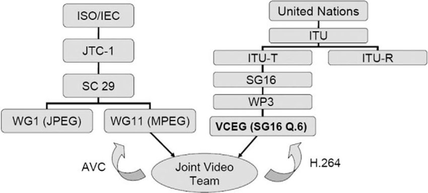
Part 10 of MPEG-4, also known as H.264, is probably the most publicly discussed part of the standard these days, as it contains the latest addition of video coding tools that have been developed by the Joint Video Team (JVT). JVT consists of the joint forces of video coding experts from both the ITU and MPEG. The ITU experts developed the major part of the technology, which was later adopted and further integrated into the MPEG-4 standard. The corresponding ITU title for this excellent piece of technology is H.264.
How did this come about? Around the year 2000, the discussion in the world of video compression concerned the quest for better coding technology than the algorithms that had been standardized by MPEG-4 thus far. MPEG decided to issue a Call for Evidence. This call invited all parties to bring examples of their coding technology to the next MPEG meeting and to demonstrate their tools in an informal way to MPEG experts. At the next meeting, a number of interesting approaches were demonstrated very effectively.
Based on those demonstrations, MPEG decided to issue a formal Call for Proposals for new coding technology. The quality of new proposals was to be assessed by means of a round of subjective quality testing under controlled and fair-testing conditions. The results of the subjective tests were presented and discussed during the MPEG meeting in Sydney, Australia, in 2001. The proposal submitted by the ITU video coding experts, known under the project name H.26L, turned out to be the best technology among the candidates.
What followed was that the Joint Video Team (JVT) was formed, as described above, consisting of video coding experts from the ITU and MPEG. The mandate for the JVT was to create a new joint specification for MPEG and the ITU, based on the H.26L proposal, within a very short time frame. This activity on the ISO side led to the creation of Part-10 of MPEG-4, called “Advanced Video Coding,” and on the ITU side, it led to the standard called “H.264.” Technical features that were added to H.26L through the work of JVT include the support for interlaced video, which is still an important scanning format in the world of television. AVC/H.26L is currently limited to the coding of rectangular-shaped video objects. However, if the object-oriented video coding paradigm one day takes off, MPEG will be open enough to further extend AVC/H.264 to also support shaped video objects.
AVC contains a list of technical innovations that lead to improved coding performance. The fundamental concept of a hybrid codec based on motion-compensated prediction and transform coding using an integer-valued variant of the discrete cosine transform (DCT) still forms the backbone of the codec. This is conceptually the same signal processing ingredients as used in MPEG-1 and MPEG-2 and MPEG-4 Visual. So AVC/H.264 is not a revolution, but can be seen as another step in the evolution of video coding technology. In that sense, AVC represents a sustaining innovation, pushing forward products and services in an established value network.
Figure 3.13 The genesis of the Joint Video Team (JVT) and its parents, ISO and ITU.
As soon as the technical work was done, subjective quality tests were performed by the end of 2003 to assess the coding performance of AVC/H.264 in comparison with previously specified MPEG standards such as MPEG-2 and the previous versions of MPEG-4 Visual. The bottom line coming out of those tests was that AVC/H.264 offers coding performance gains against previous standards that lie typically around a factor of 2 and sometimes more. Besides the improvement in terms of compression performance, the implementation complexity for AVC/H.264 is also higher than for previous coding standards. As microelectronics technology is advancing, this higher complexity tends not to be a problem for the industry in the long run. However, it is a dimension that needs to be investigated thoroughly when choosing a video coding technology to be integrated into a new application. The question may be to determine if the improved coding is worth the additional implementation cost. In some cases it will be and in others it won’t.
When it comes to coding video, this improvement is dramatic. It is relatively easy to see the next logical step, that a compression-based business model benefits from such an improvement in compression technology. We’ll cover that aspect in more detail in a later chapter.
3.4.2.3. Still-Image Compression—Texture Coding
Besides coding arbitrarily shaped video objects, that is, moving pictures, MPEG-4 Visual also addresses the coding of still images (textures), which also may exhibit an arbitrary shape. An important ingredient for generating synthetic visual objects is the projection of the texture onto a synthetic 3D object, which comes as a 3D mesh, and which defines the geometry of the object in 3D space. This process is commonly referred to as “texture mapping.” Still images may also be used as a static background texture for a 2D video scene.
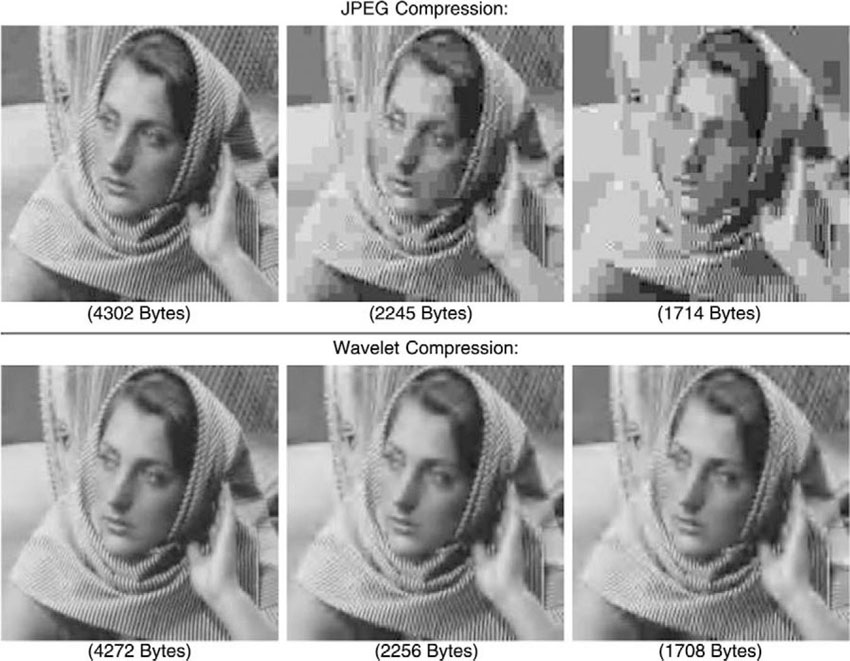
MPEG-4 Visual employs an algorithm for coding still textures that uses wavelets’ transformations. The wavelet transformation has a number of favorable technical features for achieving high-compression factors, while offering very elegant scalability properties. However, it is worth noting that the MPEG algorithm for compressing still images is different from the wavelet-based coding algorithm adopted in JPEG2000. The MPEG tool for still-image compression is inferior in terms of coding efficiency when compared to the JPEG2000 algorithm. A valid question is then, why has MPEG adopted an inferior algorithm if there is ISO’s JPEG 2000 standard, issued by MPEG’s sibling working group WG 1. The reason is that the schedules for the two standards, MPEG-4 and JPEG2000, were not aligned. While MPEG-4 had progressed to a certain level of maturity, JPEG2000 was still in an early stage and lagging behind MPEG-4. In 1996, MPEG realized the urgent need for a still-image coding tool as an important ingredient to make synthetic video fly. MPEG experts inspected the schedule of the JPEG2000 standardization project and discovered that the sibling standard was too much behind MPEG’s time line. Even though MPEG members were in favor of adopting an algorithm from JPEG, MPEG could not afford to wait for JPEG2000 to provide a solution without sacrificing its own delivery deadline. As sticking to dead-lines is one of the basic principles in MPEG standardization, the decision was made to develop a still-image codec within MPEG.
Figure 3.14 Still-texture coding in MPEG-4.
3.4.2.4. 2D Animated Meshes
This is a technology to turn still images into animated video clips or to modify (edit) the motion associated with a given video object. A 2D mesh is placed on top of a still image, for example. A visualization of this looks a bit like a rendition of a “Spiderman look.” The nodes of the mesh can then be displaced according to motion information taken from elsewhere or according to some interactive action. The pixels around the displaced nodes are moved around accordingly. The resulting effect then looks like the pixels are moving, as determined by the externally imprinted motion information. For an example, think of a photograph of a person’s face onto which the typical motion of a cloth flapping in the wind can be applied to generate an animation effect that looks like the image of the face being printed on a flag. Another simple example is to apply the motion pattern of a winking eye to the image of Mona Lisa, thus bringing her to life. Yet another idea might be to use 2D mesh animation for lip sync in order to convincingly dub foreign language movies by changing the movements of the lips to match the dubbed language. While European customers are used to the mismatch between lip movement and actual speech, U.S. customers tend to be annoyed at the technique of dubbing. However, reading subtitles is not that thrilling, either. 2D mesh animation is a tool that allows interactive manipulation of pixel-based visual objects and is still waiting to reach its prime time.
3.4.2.5. Sprite Coding
A sprite is a term that was first used in computer graphics or computer gaming, where a sprite is a relatively small piece of graphic or texture that can be used as an atom to build animated graphics in interactive computer games, such as jump-and-run games like “Super Mario Land” or similar. In MPEG-4, the term is used to mean something slightly different. In this context, a sprite is a kind of large still image that can be used as the backdrop of a scene into which other visual objects can be placed for interactive applications. In the context of interactive TV applications, Sprite Coding is a powerful tool to achieve high compression at the same time as interactivity. Sprite coding comes in a number of flavors, which differ mainly in terms of the technical details, for example, different levels of acceptable delay or the capability to generate sprites online. As sprite coding is a powerful but expensive tool, it is not yet included in the mainstream of MPEG-4-based product announcements. However, it is definitely a hot piece of technology, which may be considered for inclusion into video surveillance products of the future. A sprite can be generated, for example, for a surveillance camera that is panning back and forth collecting information about the scene. In such a case, it may be beneficial to build up a background sprite of a parking lot and only transmit the cars and people moving in and out as separate video objects.
Figure 3.15 A 2D mesh overlay over a fishy object

[Source: MPEG-4 Overview].
Figure 3.16 An example of Sprite Coding. The background image is coded as a sprite. The figure of the tennis player is glued onto the background and coded as a separate video object with arbitrary shape. For interactivity, the user may exchange Wimbledon center court for Roland Garros

[Source: MPEG-4 Overview].
3.4.2.6. Interlaced Coding Tools
Nobody in the video coding community is in favor of video sources that have been scanned in an interlaced way. Within MPEG-4, this topic has been excluded from serious consideration since MPEG-4 was initially aiming at very low bit rate coding for communications applications, a realm of digital video where interlacing is not a topic. As soon as the new coding technologies became intriguing for entertainment-type video content, that is, when television-oriented companies started to have an eye on the emerging technology, interlacing became an active subject in standardization circles. The reason for this is the enormous amount of legacy video material stored in the cellars of TV stations and elsewhere. In order to be able to (re-)use this stock of existing audio-visual content, interlacing is a sad fact of life. MPEG-4 has addressed this aspect by specifying video-coding tools that are able to natively deal with interlaced video sources. The result of using these tools is better coding performance for interlaced video material when compared to coding such material while ignoring its interlaced nature. In other words, for TV-centric applications, interlaced coding tools are beneficial. For showing pictures only on computer screens or handheld devices, you can save the money by not including interlaced coding tools.
3.4.2.7. Alpha Shape Coding
For applications where image quality when dealing with arbitrarily shaped video objects is the ultimate criterion of merit, Alpha Shape Coding tools have been developed and standardized. Alpha shape coding allows the shape of a video object to be described with gray-level values. The alternative is to use only a two-valued data, i.e., zeros and ones, to denote if a pixel belongs to an object or not. Those binary-valued object shapes tend to create somewhat artificial-looking compositions that are of unacceptable quality, for example, in studio applications. This is why alpha shape coding tools were introduced. However, it should be noted that alpha shape coding comes with a price tag of increased implementation complexity as well as higher bit rate requirements. So if your anticipated application needs are simple and your requirements are for a low-transmission bandwidth, then you don’t want alpha shape coding. If, however, you are planning to create video material with Hollywood quality, then you will need it.
3.4.2.8. Synthetic Video
A unique asset of MPEG-4 Visual is that its objects need not be natural images, that is, the images can be synthetically generated. To this end, MPEG-4 Visual supports 2D and 3D meshes that may model the geometry of complete generic 2D/3D objects. The 2D/3D meshes, and hence the geometry of the object, can be modified in time in order to create a computer-generated video sequence of animated characters. 2D/3D meshes are an established tool in the bag of tricks of computer graphics. They are commonly used in Hollywood and elsewhere to generate artificial characters such as the dinosaurs in the motion picture Jurassic Park (3D meshes), or to modify the appearance of real images in a spectacular way, such as in the motion picture Terminator 2.
Since MPEG is mainly concerned with the bit-efficient representation of media objects, its main contribution to the field of 3D mesh-based computer graphics is to devise methods and standardize an algorithm to compress those 3D meshes. Thus, a 3D mesh becomes yet another visual object type that is tightly integrated into the media standard. In this context, the kick comes from making these sophisticated media objects streamable over band-limited channels. Figure 3.18 depicts an example in which simple 3D graphics can be used on a handheld device for a media-based application.
Figure 3.17 3D mesh object

[Source: Gabriel Taubin, IBM].
Figure 3.18 3D mesh object on a handheld device
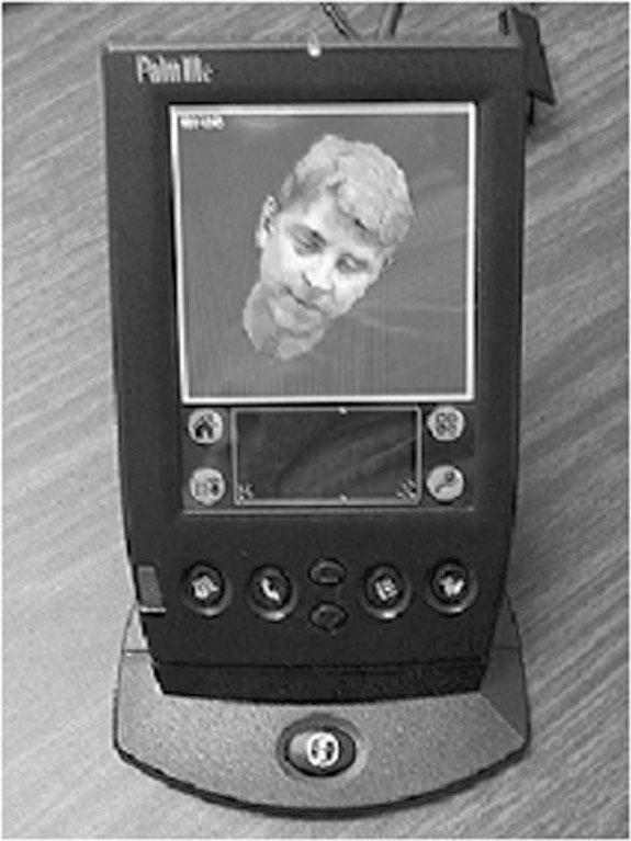
[Source: Gabriel Taubin, IBM].
Within the domain of synthetic video, a special emphasis is given to dealing with synthetic human faces and bodies (Avatars), which may be represented by predefined 2D or 3D meshes, where certain feature points are specified. The meshes can be designed to look like “real” faces by either shading the surfaces of the mesh or mapping texture onto the mesh. For this we need still-image textures (see above). The feature points of the mesh describing faces or bodies may be animated by means of moving them around. The displaced feature points influence the appearance of the textures, which in turn creates the impression that the face or the bodies are moving, making it possible to create face or body animation (Avatars). The necessary amount of bits to be transmitted to perform a face animation, for example, is very low—in the range of a few kilobits per second. Face animation in combination with Text-to-Speech synthesis is a very bit efficient way to use talking heads in a multimedia application.
Figure 3.19 Example of a face animation object
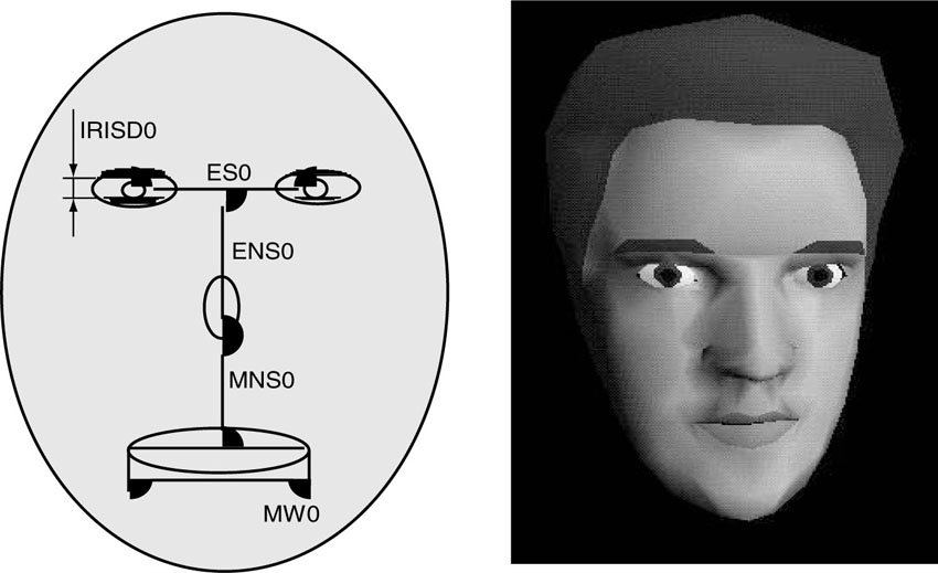
[Source: MPEG-4 Overview].
3.4.3. ISO/IEC 14496-3—Audio
Part 3 specifies the coded representation of natural and synthetic audio objects. Even though for Part 3 the conventional notion of audio has been extended to support more general types of audible information, the people in the audio group did not wish to change the name to the more general term, “aural.” (Admittedly, “aural” sounds funny in this context if you utter it aloud.)
3.4.3.1. Audio Compression
MPEG-4 Audio provides a complete coverage of the bit rate range, starting as low as 2 kbit/s and going up as high as 64 kbit/s. Good speech quality is obtained already at 2 kbit/s, and transparent quality of monophonic music (sampled at 48 kHz at 16 bits per sample) is obtained at 64 kbit/s. Three classes of algorithms are used in the standard.
The first class covers the low bit rate range and has been designed to encode speech. For speech signals, separate codecs are part of the MPEG-4 toolbox. Speech codecs allow operation at 2 to 24 kb/s. The second class can be used in the midrange bit rate to encode both speech and music at an acceptable quality for music. The third class can be used in the high bit rate range and is targeted to be used for high-quality music. For audio signals at the highest quality level, MPEG-4 includes the advanced audio coding (AAC) algorithm. The algorithm provides CD-quality audio at considerably lower bit rates than the mp3 audio format.
Examples of additional functionality are speed control and pitch change for speech signals. The speed control functionality allows the playback of an audio signal to be slowed down or sped up without altering the pitch during this process. This can, for example, be used to implement a “fast forward” function (database search) or to adapt the length of an audio sequence to a given video sequence. For a music student who needs to practice his or her piano playing along with a combo or orchestra, it is a helpful feature if it is possible to choose a slower playback speed for the combo or orchestra without a change in the pitch. The pitch change functionality allows a change of pitch without altering the speed during the recording or playback process. This can be used, for example, for voice alteration or Karaoke-type applications. This technique only applies to parametric and structured audio coding methods.
Audio Effects provide the ability to process decoded audio signals with complete timing accuracy to achieve functions for mixing, reverberation, and spatialization. By the term “spatialization” we mean that the freedom of individually coded objects entails the need to tell the decoder where to position audio and visual objects in a scene. This is a functionality that must be provided to the author of a scene and is the MPEG-4 equivalent of the role of a movie director who instructs the scene setter to put a table here and a chair there, and asks an actor to enter a room through a door and speak a line, and another to stop talking and walk away. A human observer expects the direction of sound to coincide with the position of the corresponding visual object creating the sound.
3.4.3.2. Synthetic Audio
In the area of synthetic audio, two important technologies have been standardized. The first is a Text-to-Speech (TTS) interface, i.e., a standard way to represent prosodic parameters, such as pitch contour, phoneme duration, and so on. Typically, these can be used in a proprietary TTS system to improve the synthesized speech quality and to create, with the synthetic face (face animation visual object), a complete audio-visual talking face. The TTS can also be synchronized with the facial expressions of an animated talking head. TTS coders live in the bit rate range from 200 bit/s to 1.2 kbit/s, which allows a text or a text with prosodic parameters as its inputs to generate intelligible synthetic speech. TTS includes the following functionalities:
• Speech synthesis using the prosody of the original speech
• Lip synchronization control with phoneme information
• Trick mode functionality: pause, resume, jump forward/backward
• International language and dialect support for text (i.e., it can be signaled in the bit stream which language and dialect should be used)
• International symbol support for phonemes
• Support for specifying age, gender, speech rate of the speaker
• Support for conveying facial animation parameter (FAP) bookmarks
As a completely new ingredient, MPEG-4 supports “Structured Audio.” This is a method for creating synthetic audio that operates on extremely low bit rates. Structured audio is a format for describing methods of audio synthesis algorithms. MPEG-4’s standard for it can accommodate any current or future synthesis method. Structured audio is in essence a musical score-driven synthesis method.
Using newly developed formats to specify synthesis algorithms and their control, any current or future sound-synthesis technique can be considered to create and process sound in MPEG-4. The sound quality is guaranteed to be exactly the same on every MPEG-4 decoder.
One nice application of structured audio is that a hobby musician can have the opportunity of playing along with an orchestra where the hobby musician’s instrument is left out of the playback. This kind of object-based scalability allows specific objects to be de-selected from the presentation. As an additional benefit, the orchestra can play a piece much slower, in order for the hobbyist to be able to follow, without experiencing a pitch shift.
3.4.4. ISO/IEC 14496-4—Conformance Testing
Part 4 defines conformance conditions for bit streams and devices. This part is used to test the compliance of MPEG-4 implementations. Conformance is an important step toward interoperability, one of the major motivations of standardization. The standard offers bit streams that contain audio-visual presentations corresponding to the specified profiles. These bit streams are then decoded by a newly developed device, which has to produce an output (i.e., a presentation that stays within specified bounds from the reference), as laid down in MPEG-4 Part 4. If a device passes the conformance test, it is judged as conforming to the standard. The conformance test is a kind of self-certification procedure.
Even if a device can rightfully claim to conform to the MPEG-4 standard, it is not automatically guaranteed that the device is fully interoperable with other devices in the market. Achieving true interoperability takes extra effort. The MPEG Industry Forum has been very active in establishing programs and activities that are aimed at achieving full interoperability between as many vendors as possible. For more details, the reader may want to check the corresponding Web site as cited in the references.
3.4.5. ISO/IEC 14496-5—Reference Software
Part 5 comprises software corresponding to most parts of MPEG-4. The software includes normative and non-normative tools, which means decoder as well as encoder software. The software comes as source code, which can be used freely for implementing products that claim compliance with the standard. For those cases, ISO waives the copyright of the code. Furthermore, the software is now also a normative part of the standard (Part 5). This means that there are actually two equivalent descriptions of the standardized technology. First, the textual description for the visual specifications as written down (e.g., in Part 2 of the standard). Second, there is the equivalent description of the technology as implemented by the reference software, which is Part 5 of the standard. If there is a discrepancy between the two descriptions, a more complete review of the situation is necessary in order to decide which description is correct and which needs to be fixed. This is a rather new policy brought forward by MPEG. The purpose is in part to facilitate the adoption of the standard by providing a reference implementation, which can also be used to get products to the marketplace within a short period of time. DivX, as one of the most prominent implementations of MPEG-4 Visual, is largely derived from this open-source software. The reference code for the visual part of MPEG-4 has been donated to MPEG by two independent sources. One version of the software comes from a European project in the ACTS program (5th framework), which is called MoMuSys. The other implementation has been donated by Microsoft! You can imagine the amount of effort it takes to keep both reference software implementations, plus the textual description for the Visual part, aligned.
3.4.6. ISO/IEC 14496-6—Delivery Multimedia Integration Framework (DMIF)
Much of what goes on technically during a multimedia presentation such as streaming media over the Internet or cable television takes place beneath the surface. If it is done well, then a lot of those technical processes stay completely invisible to the consumers. These essential but largely invisible aspects of an MPEG-4 terminal are covered in Part 6 of the standard. The technology covered in Parts 1, 2, and 3 of MPEG-4 are designed to be independent of the underlying delivery mechanism. That means that those parts are independent to the transmission mechanism for the audio-visual content. Candidate transmission protocols are the Internet, satellite or cable broadcast, or point-to-point communication links such as those used in telephony, as well as packeted media such as DVD or the like. One aspect of DMIF is also the ability to mix content coming from different channels in a way that is transparent to the user. As an example, think of an interactive game, where some parts of the game come from a CD-ROM and other parts come through a network connection. It is left to Part 6, the Delivery Multimedia Integration Framework (DMIF), to deal with the various technical details associated with the underlying delivery layers. It defines a session protocol for the management of multimedia streaming over generic delivery technologies. DMIF provides three types of abstraction.
The first is abstraction from the transport protocol, which can be any one of a number of Internet protocols, such as RTP/UDP/IP or MPEG-2 Transport Stream or others with the ability to identify delivery systems with different quality of service (QoS) levels. QoS level can be specified for a single object in a scene.
The second is the abstraction of the application from the delivery type—interactive (client-server), local, or broadcast delivery is seen through a single interface.
The third abstraction is from the signaling mechanisms of the delivery system. DMIF provides a practical solution to achieve one dream of content creators: “Create once; play everywhere from anywhere.”
The synchronized delivery of streaming information from source to destination, exploiting different Quality of Service parameters as made available by the network is specified in terms of the synchronization layer and a delivery layer containing a two-layer multiplexer.
3.4.7. Further MPEG Tool Sets
MPEG-4 is a standard that keeps evolving in order to meet new technical challenges and to include new solutions and approaches as they become available. Beyond the parts that have already been specified and approved, there are a few more extensions for MPEG-4 in the making. In this section, we want to give a quick overview of what else is out there on the horizon. In addition to the documents being lifted to the status of international standard, there is still the option to publish a new part of MPEG as a Technical Report. Such a report is not normative but is classified as informative. It typically contains supplementary technical information that is helpful for implementing the standard.
• ISO/IEC 14496-7—Optimized Software: Part 7 is not a normative part of the MPEG-4 standard. This document has the status of a Technical Report (TR), which is classified as being informative only. However, Part 7 provides optimized software implementation for a couple of video coding tools. In particular, the optimized software contains fast software tools for motion estimation, global motion estimation, and fast sprite generation.
• ISO/IEC 14496-8—MPEG 4 on IP (MPEG-4 Contents over IP Networks): As the title already indicates, Part 8 of MPEG-4 describes how media content represented with MPEG-4 tools can be transported over IP networks. The document indicates how the MPEG-4 content is to be mapped into several IP protocols.
• ISO/IEC 14496-9—Reference Hardware: Part 9 is another Technical Report that describes MPEG-4 tools in terms of a hardware description language (VHDL). The information is considered helpful for speeding up hardware implementations of MPEG-4 technology.
• Animation Framework eXtension (AFX): AFX—pronounced “effects”—will provide users with enhanced visual experiences in synthetic MPEG-4 environments. The framework will define a collection of interoperable tool categories that collaborate to produce a reusable architecture for interactive animated contents.
3.5. Toward Interoperable Terminals
3.5.1. Profiles
MPEG-4 covers an enormous amount of technology. It is simply impossible to envision a device or a product that comprises the entire MPEG-4 specification. Such an endeavor is not commercially viable and probably not even possible. Implementing the entire standard certainly is overkill for any one particular application. Building a product and being forced by a standard to include costly technical features and capabilities that are of no particular interest to a targeted market basically loads a major cost burden onto the product. MPEG mitigates this obvious danger of overloading products with its concept of “Profiling.” A profile in MPEG refers to the collection of specified tools that form a subset of the complete specification. A profile puts qualitative restrictions on the permissible syntactic elements to be used in a bit stream. The syntactic elements in a bit stream typically have their counterpart in the functionalities being implemented in the decoder. A profile thus describes which syntactic elements are allowed in a bit stream such that a decoder will not be stalled by a request to perform a function it has not implemented. In other words, profiling implies a restriction on the coding tools to be implemented to cap complexity and hence implementation cost. This way, MPEG terminals can be shaped to match the requirements of applications and market needs.
The range of requirements and application-specific needs is vast. For example, a mobile receiver has technical limitations and capabilities that are quite different from the capabilities of a broadcast set-top box. The applications for each device also look quite different. It would be inappropriate to equip both devices with the same set of functionalities and features.
It is up to the individual markets and players to pick an existing profile or to request from MPEG the definition of a new profile to make their products and services fly. Each application domain or industry may request from MPEG an appropriate toolset to satisfy its needs for bit-efficient representation and control of audio-visual content. In this way, the market in fact decides which parts of MPEG-4 will be successful and which will not.
3.5.2. Levels
The profiling concept is complemented by a second area, in which so-called “Levels” are defined. For each profile, a number of levels are defined. These levels put quantitative restrictions on parameters, which determine the implementation complexity in terms of required computational capabilities and memory requirements. The two dimensions, computational capability and memory size, are the dominant factors for determining the cost of an MPEG decoder. The levels are specified by putting quantitative limits on, for example, the maximum permissible bit rate, or maximum number of objects in a scene, the maximum macro blocks per second, maximum sampling frequency and channels, or the maximum number of pixels in the vertical and horizontal direction. All these parameters have an immediate influence on the implementation complexity for a terminal. The level determines the maximum or worst-case requirements a terminal has to be able to handle in real time in order to achieve compliance with the standard. The terminal is always allowed to offer more resources than necessary if the manufacturer thinks this is useful, but it shall never offer fewer capabilities than specified by the respective level.
To offer an example, let’s say that there is an industry consortium putting together the technologies and standards on which the participants want to base their future systems and products. As the technical experts of this consortium are scanning the MPEG profiles in order to find an appropriate candidate, they find out that none of the profiles will satisfy their needs at an acceptable level. In such a situation, representatives of the consortium then address MPEG with the request to specify a new profile that contains all tools the consortium think is necessary for its field. If there is in fact a good technical reason why none of the existing profiles can be used, or if the consortium simply represents a major business opportunity for MPEG technology, then MPEG may issue another profile for the consortium.
Just to be clear on the meaning of the limits set by the various levels. For the sake of explanation, let us consider a level definition for a certain visual profile specifying that the bit stream, in order to be compliant, must not exceed a bit rate of, say, 128 kbit/sec. A decoder, in order to be compliant to this specification, has to be able to digest at least 128 kbit/sec. It may well be able to accept 500 kbit/sec, or even higher if this is desired by the product designer. In other words, for the decoder, the limits given by the level definition are interpreted as lower limits, while for the bit streams and the encoder, those definitions are interpreted as upper limits.
Figure 3.20 Conceptual difference between Profiles and Levels.
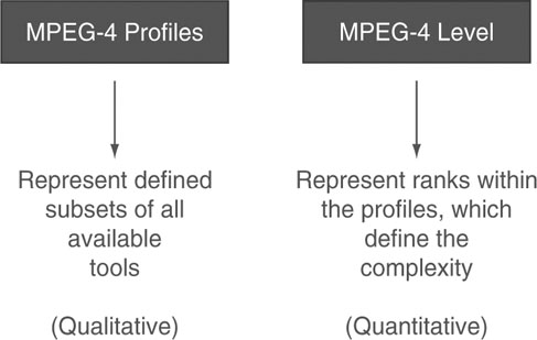
3.5.3. Conformance Points
The two concepts, profile and level, are intimately related. Pairing up one profile and one level is meant to define a so-called conformance point. Devices can be tested as to whether they fulfill the specifications of a particular conformance point. A Profile@Level combination allows a codec builder to implement only the subset of the standard he needs, while establishing a basis for achieving interoperability between MPEG-4 devices built to the same specification, and checking whether MPEG-4 devices comply with the standard (conformance testing).
Profiles and levels are a normative part of the standard, i.e., an implementation of MPEG-4 must conform to a Profile@Level combination if it claims to be compliant with the standard. Thus, each Profile@Level combination determines a conformance point.
The ultimate purpose of developing the concepts of profiles and levels is to achieve interoperability between devices within one profile and level definition. Furthermore, the definition of profiles and levels is done in a way to maximize interoperability between devices adhering to different profiles. Complete interoperability in the latter sense cannot be achieved because one profile may be “richer” than another in terms of the number and type of functionalities or tools.
Profiles exist for various types of media content (audio, visual, and graphics) as well as for scene descriptions. MPEG does not prescribe or advise combinations of these profiles, but care has been taken that good matches exist between the different areas.
Not unlike its predecessors, MPEG-4 would have a reduced impact if an MPEG-4 decoder would have to be able to decode all of the MPEG-4 tools. Furthermore, following the traditional approach of keeping the individual parts of the standard (Audio, Video, Systems, and DMIF) separate, profiles are only defined for the individual parts and not for Audio, Video, Systems, and DMIF combinations. This means that an application developer can just choose the parts of the standard he or she needs, and for each part, the profile that best suits his or her application.
Finally, the approach to specify conformance and interoperability originates from domains where devices have a more or less fixed set of capabilities and where it is expected for the device to guarantee the quality of service. This can be termed a “guaranteed quality” concept. The alternative approach can be called “best effort,” where the quality of a service is not guaranteed, but the devices are doing the best they can. As examples for both conceptual frameworks, think of TV services, where it is expected that the broadcast will be displayed in real time and an acceptable image and audio quality, irrespective of the channel you have chosen and whether the content is a news cast or a feature movie. A “best effort” approach is more commonplace in the computer world, where a consumer has to learn that her last year’s (and hence obsolete) computer is currently unable to perform a certain computer game unless the consumer buys herself a software update or a new graphics card or a new computer altogether. Even if the computer can execute the computer game, it may be that the game is slowed down, as the rendering speed of the machine only permits play at “slow-motion” speed.
3.5.4. Profiles and Levels in the MPEG-2 Standard
A prominent example of the effectiveness of the profiling approach is MPEG-2 Video. At the time of development, some industries requested the standard to be scalable (i.e., capable of extracting a subset of the stream and still obtain a usable picture). Other industries were not interested in this feature and opposed its introduction because of the increased decoder complexity that they would have had to bear. The profile approach provided the solution of defining a non-scalable profile (called Main Profile) and a set of scalable profiles. A scalable profile decoder can decode a Main Profile bit stream. Eventually, all implementations came to be based on the Main Profile. For standard-resolution (SD) television services, the size of the images is restricted to 576 × 720 pels coming in a rate of 25 frames per second (PAL) or 480 × 720 pels at a rate of approximately 30 frames per second. The SD television service application is supported by a decoder compliant with the Main Profile@Main Level. Main Level has been specified to allow picture sizes up to 576 × 720 pels at a maximum frequency of 30 frames per second, and the total bit rate for the coded video is limited to 15 Mbit/sec.
As high-definition television (HDTV) becomes more prevalent, a decoder is needed that supports larger images (1080 × 1920) and that can digest a high bit rate for the coded bit stream at the input. The video coding tools offered by the Main Profile are considered to be sufficient (and in fact they are). This is why HDTV services only need a level definition that exceeds the Main Level definition to satisfy the higher demands. The corresponding level in MPEG-2 is called “High Level,” supporting HDTV image sizes (see above) and bit rates of up to 80 Mbits/sec. An overview of the profiles and levels defined in MPEG-2 is shown in Figure 3.21. Note the circle that indicates the Main Profile@Main Level conformance point, which comprises over 90% of all MPEG-2 implementations.
Figure 3.21 Table of Profiles and Levels in MPEG-2 Video
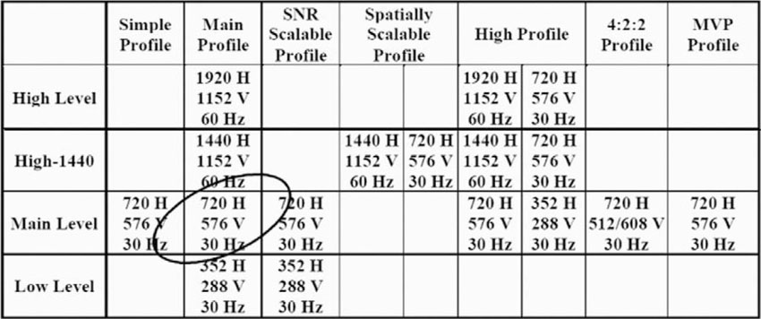
This type of solution has been very effective in promoting adoption of the standard. The first consumer electronics products were based on MPEG-1 Audio Layer 1 because of limited complexity and battery life. Immediately after that, Layer 2 was used in digital television set-top boxes where battery life was not a concern. The constant progress of number-crunching capabilities of personal computers has made software Layer 3 decoders possible on PCs. From the service provider and consumer point of view, this is a very positive situation because content produced in the first phases of the technology can still be played back on the newer decoders.
3.6. Overview of Profiles in MPEG-4
An MPEG-4 terminal may be composed of different independently chosen components. The choice of the components included depends on the application. It is also possible to combine MPEG tools with other non-MPEG tools. This is done with success in the DVD player market, where MPEG-2 Video is used for coding video and Dolby Digital is used for coding of audio signals. Outside of the United States, MPEG-2 Audio was originally used. By now, most consumer DVD players support both formats. In Figure 3.22, the concept is shown graphically, in which different profiles as part of the MPEG-4 standard may be combined. A more detailed description of the profiles and their basic capabilities is given in the following paragraphs.
Figure 3.22 Combining profiles for terminals.
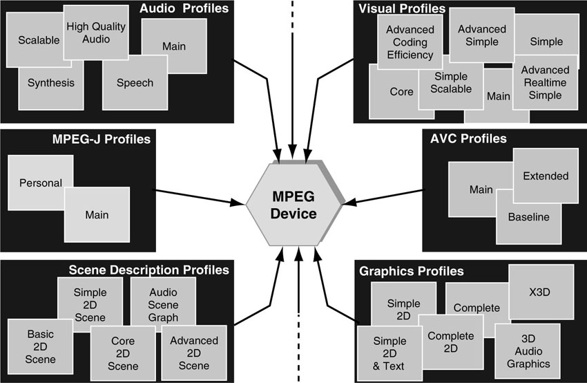
3.6.1. Visual Profiles
When considering the visual part of MPEG-4, one needs to abandon the idea of a single-purposed video coding standard addressing the needs of one dominant industry. MPEG-4 is much more a toolbox standard offering a wealth of technology to enable and foster a wide range of products and services all dealing with interactive multimedia. This is the reason such a large number of profiles have been defined to choose from. There has been a considerable amount of discussion about whether it is sensible to define such an excessive number of visual profiles. As it stands, the developers of new applications can choose the most appropriate profile that satisfies their needs best and that provides a reasonable basis for deploying interoperable terminals. This way the market actually determines which profiles will be implemented and will stand the test of time. It is to be expected that quite a few of the profiles mentioned in the sequel will never be implemented commercially.
Let’s have a quick overview of the visual profiles.
3.6.1.1. Simple Visual Profile
The Simple Visual Profile (SP) provides efficient, error-resilient coding of rectangular video objects, suitable for applications on mobile networks. The profile has a strong similarity to the coding technology included in ITU’s H.263 standard. The Simple Visual Profile is targeted toward low-complexity decoders and small displays. A prominent example is wireless channels and mobile receiving devices. Simple Profile has been adopted initially by the 3GPP consortium for the roll-out of 3rd-generation mobile receivers to enable multimedia applications on cell phones. Simple Profile is also attractive if real-time encoding in software on desktop platforms is a requested feature. Simple Profile sacrifices some compression performance to support low-delay coding, which is a common requirement in bi-directional communication applications such as videophone or teleconferencing. Simple Profile is also usable for applications that employ streaming video on the Internet. In spite of public dismay at the inferior visual quality offered by this profile, it still is able to deploy reasonably good video services at relatively low implementation cost. It is not the latest, hottest, and coolest video codec, but it is better than its reputation implies. Note that the Simple Profile does not support the native treatment of interlaced video sources. Simple Profile is not seriously considered as a profile to be used for TV services, or more generally, for video services asking for large images and premium image quality.
3.6.1.2. The Advanced Simple Profile
The Advanced Simple Profile (ASP) adds a few coding tools (B-frames, 1/4-pel motion compensation, extra quantization tables and global motion compensation, interlaced video coding tools) to the Simple Visual Profile in order to achieve better compression performance (i.e., 25 to 30% better compression than Simple Profile) at the price of a slightly higher implementation complexity. This has been considered an interesting visual profile for building streaming applications on the Web or for TV applications (as a replacement for MPEG-2). Advanced Simple is the profile for all applications where improved coding efficiency for rectangular-shaped video is of primary importance. The supported bit rates of up to 8 Mbit/sec and image formats reaching CCIR-601 or 4CIF (TV screen size) resolution, together with the support for interlaced video, makes MPEG-4 ASP an attractive technology platform for broadcasting services. Advanced Simple Profile has been selected by ISMA (Internet Streaming Media Alliance) to be used for streaming media applications over the Internet. MPEG-4 ASP is also an attractive candidate for building streaming services supporting a wide range of transmission bandwidths between narrowband modem connections (56 kbit/s), from DSL bit rates (300–750 kbit/sec) up to broadband streaming in the range of 1–2 Mbit/sec. Until AVC/H.264 was adopted by MPEG, ASP codecs were considered the flagship codecs of MPEG-4, offering the best video coding performance, outperforming MPEG-2 codecs in the TV-relevant bit rate domain of 1–4 Mbit/sec. ASP also includes support for interlaced video, making it a contender for future TV services. In particular for its use in digital video security systems (CCTV), the “Global Motion Compensation” tool promises to excel at video content where panning and zooming cameras are dominant. The benefit for ASP is that there are already a number of well-performing codecs in existence for this profile. One more comment regarding ASP: During the early days of the ASP decoder, a product brochure was published in which a company announced that it offered decoder chips targeted at the set-top box market that were implementing the Advanced Simple Profile. The brochure came with a little footnote that stated that the chips do not support 1/4-pel and global motion compensation. Looking back at the original meaning of Profile definitions, it becomes clear that this offering did not represent a compliant ASP decoder implementation, since in a decoder, all specified coding tools are mandatory for compliance. In other words, this was a cheap marketing trick to jump on the bandwagon.
3.6.1.3. The Fine Granularity Scalability Profile
The Fine Granularity Scalability Profile comes in combination with either the Simple or Advanced Simple profile. The profile offers a scalable coding mode where the so-called “base layer” is designed to deliver a basic quality video service. An additional bit stream, the “enhancement layer,” is sent along. The bits coming with the enhancement layer allow gradual improvement of the received video as more bandwidth is available. It allows the truncation of the enhancement layer bit stream at any bit position so that delivery quality can easily adapt to transmission and decoding circumstances. The main point of this profile is that video quality follows the variations of the transmission bandwidth in fine granular steps so as to mimic the graceful degradation behavior of analog video reception. This feature may be attractive for situations where the transmission bandwidth is subject to significant temporal variations. Proprietary video codecs, such as Real Networks’ or Microsoft’s offerings, also implement related approaches to overcome the bandwidth variations experienced in Internet streaming applications. As is often the case with scalable video coding, this coding approach suffers from losses in compression efficiency in order to achieve the scalability functionality. MPEG is about to produce more technology under the title “scalable video coding” (SVC) to fulfill this desire for scalability and efficiency.
3.6.1.4. The Simple Studio Profile
The Simple Studio Profile is a profile that has been designed by companies interested in video post-production applications. It offers very high visual quality for use in studio editing applications. It is an I-frame-only codec so frame-exact editing and random access is easily achieved. The profile includes the tools to code arbitrarily shaped video objects and multiple alpha channels. Shaped video objects are made possible in television production studios by means of chroma-keying techniques (blue-screen). Furthermore, blending and mixing of objects are commonplace operations in studio applications. The range of bit rates supported by this profile goes up to almost 2 Gigabits per second. The profile is of interest for the development of studio equipment that can deal with compressed video data while still enabling ease of editing and uncompromised video quality. Sony has a strong position when it comes to shaping the Studio Profile to be used in HD editing systems, similar to MPEG-IMX in the SD domain.
3.6.1.5. The Core Studio Profile
The Core Studio Profile adds P-frames to the Simple Studio Profile; that is, the video compression is more efficient, but the implementation is more complex.
3.6.1.6. The Advanced Real-Time Simple (ARTS) Profile
The Advanced Real-Time Simple (ARTS) Profile includes advanced error-resilient coding techniques for rectangular video objects using a back channel. For real-time communications applications such as the videophone, teleconferencing (over IP networks), and remote observation, the design has been tuned to offer improved temporal resolution stability and low buffering delay.
3.6.1.7. The Simple Scalable Visual Profile
The Simple Scalable Visual Profile is based on the Simple Visual Profile and adds support for coding of temporally and spatially scalable objects. It is designed to be useful for applications that provide services at more than one level of quality due to bit-rate or decoder resource limitations, such as Internet use and software decoding.
3.6.1.8. The Core Visual Profile
The Core Visual Profile is based on the Simple Visual Profile and adds support for coding of arbitrarily shaped and temporally scalable objects. It is designed to be useful for applications that provide relatively simple levels of interactivity (such as Internet multimedia applications).
3.6.1.9. The Main Visual Profile
The Main Visual Profile is based on the Core Visual Profile and adds support for coding of interlaced video objects, semi-transparent objects (alpha channel), and sprite objects. It is designed to be useful for interactive and entertainment-quality broadcast and DVD applications. So far, the profile has often been considered to be too heavy for implementation in actual applications, but if truly interactive TV services make it to center stage, this profile may be reconsidered for its interactive features.
3.6.1.10. The N-Bit Visual Profile
The N-Bit Visual Profile takes the Core Visual Profile and adds support for coding video objects with pixel depths ranging from 4 to 12 bits. It has been designed for use in surveillance applications where the infrared cameras produce gray-value images (no color information needed) with a high dynamic range for which the commonly used 8 bits of dynamic range are considered insufficient. This is clearly a very special profile for which it may be difficult to find a mass market, but the 12-bit feature certainly has interesting potential for surveillance video.
3.6.1.11. The Core Scalable Profile
The Core Scalable Profile starts with the Core Visual Profile and adds tools for coding of temporally and spatially scalable, arbitrarily shaped video objects. Note that the Core Visual Profile already includes simplified mechanisms for enabling temporal scalability. This profile offers a more complete set of tools for supporting fully scalable functionalities such as object-based SNR and full spatial/temporal scalability for regions or objects of interest. It is yet another profile that may turn out to be useful for applications such as the Internet, mobile, and broadcast services.
3.6.1.12. The Advanced Core Profile
The Advanced Core Profile combines tools and features from two less advanced profiles. It takes the ability to decode arbitrarily shaped video objects from the Core Visual Profile and combines this with the ability to decode arbitrarily shaped scalable still-image objects from the Advanced Scalable Texture Profile. This profile is meant to be suitable for various content-rich multimedia applications such as interactive multimedia streaming over the Internet.
3.6.1.13. The Advanced Coding Efficiency (ACE) Profile
The Advanced Coding Efficiency (ACE) Profile is an extension of the Advanced Simple Visual Profile. ACE inherits all the coding efficiency tools from ASP and adds further tools to compress arbitrarily shaped video objects. It is suitable for applications such as mobile broadcast reception, the acquisition of image sequences (e.g., from camcorders), and other applications where high coding efficiency is desired for rectangular and arbitrarily shaped video objects, and a small footprint is not the prime concern. ACE has been specified as an alternative to the Main Visual Profile that can achieve maximum compression while not having to support sprite coding, which is considered heavy in terms of implementation complexity.
3.6.1.14. The Simple Facial Animation Visual Profile
The Simple Facial Animation Visual Profile offers a simple means to animate a face model. The technology is meant to be suitable for applications such as audio/video presentation for the hearing impaired and online kiosks.
3.6.1.15. The Scalable Texture Visual Profile
The Scalable Texture Visual Profile provides spatially scalable coding of still images (aka texture objects). It is useful for applications that require multiple scalability levels, such as mapping texture onto 3D mesh objects in interactive games, and as a storage format used in high-resolution digital still cameras.
3.6.1.16. The Basic Animated 2D Texture Visual Profile
The Basic Animated 2D Texture Visual Profile provides spatial scalability, SNR scalability, and mesh-based animation for still-image (textures) objects as well as simple face-object animation. No real application of this profile is known to the authors.
3.6.1.17. The Advanced Scalable Texture Profile
The Advanced Scalable Texture Profile supports decoding of arbitrarily shaped texture and still images including scalable shape coding, wavelet tiling, and error resilience. It is useful for applications that require fast random access as well as multiple scalability levels and arbitrarily shaped coding of still objects. Examples are fast content-based still-image browsing on the Internet, multimedia-enabled PDAs, and Internet-ready high-resolution digital still cameras.
3.6.1.18. The Simple Face and Body Animation Profile
The Simple Face and Body Animation Profile is a superset of the Simple Face Animation Profile, which has added body animation.
3.6.1.19. The Hybrid Visual Profile
The Hybrid Visual Profile combines the ability to decode arbitrarily shaped and temporally scalable natural video objects (as in the Core Visual Profile) with the ability to decode several synthetic and hybrid objects, including simple-face and animated still-image objects. It appears to be suitable for various content-rich multimedia applications. More concrete examples of its use are not known to the authors.
3.6.2. Profiles for H.264/AVC
AVC contains a rich set of video coding tools that mainly address improved compression and improved error robustness. Object orientation and coding of shaped video objects has not been addressed in this context to date. The profiles defined for AVC try to address the dominant needs for better video compression for the industries that are expected to benefit the most from the progress in video coding technology, notably broadcasting, Internet streaming, and mobile communications.
A decoder may choose to implement one of the following three profiles, which are currently defined:
3.6.2.1. The AVC Baseline Profile
The AVC Baseline Profile includes basic video coding tools (I-slices, P-slices, error-resilience tools, and context-adaptive variable-length coding [CAVLC]), and leaves out some of the constructs that are more costly to implement. This profile does not contain B, SP, and SI-slices; interlace coding, and context-adaptive binary-arithmetic coding [CABAC] tools. It was designed with those applications in mind that run on platforms with low processing power and in hostile transmission environments with large packet losses or a high probability of transmission errors. A typical example is mobile communication and wireless services. Among the three AVC profiles, it has the least coding efficiency and is probably the cheapest to implement.
Figure 3.23 AVC Profiles
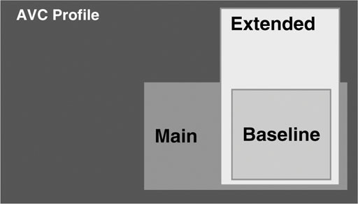
3.6.2.2. The AVC Extended Profile
The AVC Extended Profile is a superset of the Baseline profile and includes the heavier coding tools that mainly provide additional coding efficiency (B, SP, and SI-slices, and interlace coding tools); that is, the extended profiles adds those tools to the set already included in the Baseline Profile. The inclusion of interlaced coding tools is an indication that the Extended Profile may be used for broadcasting applications. It is more complex than Baseline and provides better coding efficiency. Streaming media is another application area that might pick the Extended Profile as its basis for video coding.
3.6.2.3. The AVC Main Profile
The AVC Main Profile includes all the fancy video coding tools (I, P, and B-slices; interlace coding; CAVLC; and CABAC). In particular, CABAC is considered to give an extra boost to compression, but it is slightly more complex to build. CABAC also implies some subtle changes in the coding schemes, which may be challenging to combine with tasks such as simple scrambling of video content. Since the profile can be considered as “fat,” it is certainly beyond the capabilities of a mobile or wireless terminal. Main Profile does not include error-resilience tools, as it is anticipated to be used in environments where the error rate caused by the transmission channel is relatively low. On the other hand, it has been designed to provide the highest possible coding efficiency. High-definition DVDs are an example where high coding efficiency meets the almost error-free transmission channel. By now you probably get the picture.
3.6.3. Audio Profiles
For the Audio part of the standard, a number of profiles have been specified and discussed. We will now try to provide some insights into these profiles.
3.6.3.1. The Speech Profile
The Speech Profile provides a very low bit rate parametric speech coder, a narrowband/wideband speech coder, and a Text-to-Speech interface.
3.6.3.2. The Synthesis Profile
The Synthesis Profile provides score-driven audio synthesis and wave-tables synthesis as well as a Text-to-Speech Interface to generate sound and speech at very low bit rates.
3.6.3.3. The Scalable Profile
The Scalable Profile is a superset of the Speech Profile. It is designed for scalable coding of speech and music for networks, such as the Internet and narrow-band audio digital broadcasting (NADIB). The supported bit rates range from 6 kbit/s to 24 kbit/s, with audio bandwidths between 3.5 and 9 kHz.
3.6.3.4. The Main Profile
The Main Profile is a rich superset of all the other profiles, also containing coding tools supporting natural and synthetic audio.
3.6.3.5. The High Quality Audio Profile
The High Quality Audio Profile contains a speech coder and the Low Complexity AAC coder (Advanced Audio Coding, the successor of MP3). A new error-resilient (ER) bit stream syntax is also offered.
3.6.3.6. The Low Delay Audio Profile
The Low Delay Audio Profile contains multiple options for speech coders, the low-delay AAC coder, and the Text-to-Speech interface (TTSI). Low delay is always an important feature for bi-directional communication applications.
3.6.3.7. The Natural Audio Profile
The Natural Audio Profile contains all the natural audio coding tools available in MPEG-4, but not the synthetic ones.
3.6.3.8. The Mobile Audio Internetworking Profile
The Mobile Audio Internetworking Profile (MAUI) contains the low-delay and the scalable AAC. This profile is intended to extend communication applications using non-MPEG speech coding algorithms with high-quality audio coding capabilities.
3.7. Graphics Profiles
Graphics Profiles define which graphical and textual elements can be used in a scene. The graphics profiles are defined in the Systems part of the standard.
3.7.1.1. The Simple 2D Graphics Profile
The Simple 2D Graphics Profile provides for only those graphics elements of the BIFS tool that are necessary to place one or more visual objects in a two-dimensional scene.
3.7.1.2. The Complete 2D Graphics Profile
The Complete 2D Graphics Profile provides the full set of two-dimensional graphics functionalities and supports features such as arbitrary two-dimensional graphical elements and text, possibly in conjunction with other visual objects such as video.
3.7.1.3. The Complete Graphics Profile
The Complete Graphics Profile comprises advanced graphical elements such as elevation grids and extrusions and allows the creation of content with sophisticated lighting effects. The profile enables applications such as complex virtual worlds that exhibit a high degree of realism.
3.7.1.4. The 3D Audio Graphics Profile
The 3D Audio Graphics Profile does not propose visual rendering, but it does provide graphics tools to support the rendering of the acoustical properties of a scene (geometry, acoustics absorption, diffusion, transparency of the material). This profile may be used for applications that perform environmental spatialization of audio signals such as tele-presence applications.
3.7.1.5. The Simple 2D + Text Profile
The Simple 2D + Text Profile looks much like the Simple 2D Graphics Profile, with the added means to display moving text on screen, which can be colored or transparent. Like Simple 2D, this is a useful profile for low-complexity audio-visual devices.
3.7.1.6. The Core 2D Profile
The Core 2D Profile supports fairly simple 2D graphics and text. Meant for set-top boxes and similar devices, it can do such things as picture-in-picture, video warping for animated advertisements, logos, and so on.
3.7.1.7. The Advanced 2D Profile
The Advanced 2D Profile contains tools for advanced 2D graphics. Using it, one can implement cartoons, games, advanced graphical user interfaces, and complex streamed-graphics animations.
3.7.1.8. The X3D Core Profile
The X3D Core Profile is a 3D profile that is compatible with Web3D’s X3D core profile. It provides a rich environment for games, virtual worlds, and other 3D applications.
3.8. Scene Graph Profiles
Scene Graph Profiles, defined in the Systems part of the standard, allow audio-visual scenes with audio-only, two-dimensional, three-dimensional, or mixed 2D/3D content.
3.8.1.1. The Audio Scene Graph Profile
The Audio Scene Graph Profile provides for a set of scene graph elements for use in audio-only applications. The profile supports applications like broadcast radio.
3.8.1.2. The Simple 2D Scene Graph Profile
The Simple 2D Scene Graph Profile utilizes only those BIFS scene-graph elements that are necessary to place one or more audio-visual objects in a scene. The Simple 2D Scene Graph Profile allows the creation of presentations of audio-visual content with potential update of the complete scene but no interaction capabilities. The Simple 2D Scene Graph Profile supports applications like broadcast television.
3.8.1.3. The Complete 2D Scene Graph Profile
The Complete 2D Scene Graph Profile includes all the 2D scene-description elements from the BIFS toolbox. It supports features such as 2D transformations and alpha blending. This profile enables 2D applications that require extensive and customized interactivity.
3.8.1.4. The Complete Scene Graph Profile
The Complete Scene Graph Profile unites the complete set of all scene-graph elements (2D and 3D) from the BIFS toolbox. This profile enables applications like the dynamic virtual 3D world and games.
3.8.1.5. The 3D Audio Scene Graph Profile
The 3D Audio Scene Graph Profile specifies the tools for three-dimensional sound positioning in relation either to acoustic parameters of the scene or its perceptual attributes. The user can interact with the scene by changing the position of the sound source, by changing the room effect, or moving the listening point. This profile is intended for use in audio-only applications.
3.8.1.6. The Basic 2D Profile
The Basic 2D Profile combines 2D composition for very simple scenes with audio-only and visual elements. Only basic 2D composition and audio and video nodes interfaces are included. These nodes are required to put an audio or video object in the scene.
3.8.1.7. The Core 2D Profile
The Core 2D Profile has tools for creating scenes with visual and audio objects using basic 2D composition tools. This includes quantization tools, local animation and interaction, 2D texturing, scenetree updates, and the inclusion of subscenes through Web links.
3.8.1.8. The Advanced 2D Profile
The Advanced 2D Profile forms a full superset of the Basic 2D and Core 2D profiles. It adds scripting and means for streamed animation, local interaction, and local 2D composition, as well as advanced audio.
3.8.1.9. The Main 2D Profile
The Main 2D Profile adds the FlexTime model to Core 2D, as well as Layer2D and WorldInfo nodes and all input sensors. This profile was designed to be an interoperability point with SMIL. It provides a very rich set of tools for highly interactive applications on, for example, the World Wide Web.
3.8.1.10. The X3D Core Profile
The X3D Core Profile was designed to be a common interworking point with the Web3D specifications (Web3D) and the MPEG-4 standard. The same profile will be in a Web3D specification. It includes the nodes for implementation of 3D applications on a low-footprint engine, taking into account the limitations of software renderers.
3.8.2. MPEG-J Profiles
For MPEG-J, which is included in the Systems part of the standard, two profiles have been specified.
3.8.2.1. The Personal Profile
The Personal Profile—This is a lightweight package that targets personal devices. The profile addresses a range of constrained devices including mobile and portable devices such as cell video phones, PDAs, and personal gaming devices. This profile includes the Network Scene Resource API.
3.8.2.2. The Main Profile
The Main Profile—This includes all the MPEG-J APIs. The Main profile addresses a range of consumer devices including entertainment devices such as set-top boxes, computer-based multimedia systems, etc. It is a superset of the Personal Profile. In addition to the packages in the Personal Profile, this profile includes Decoder API, the Decoder Functionality Section Filter API, and the Service Information API.
3.9. Testing in MPEG-4
Progress in any engineering discipline needs to be assessable and measurable. Of course, this is also true for many other scientific fields, but here we will limit our scope to the engineering aspect. The process of measuring, counting, and weighing is intimately related to a consensus on the figures of merit that are used to assess progress. However, assessing the quality of products and services, the quality of a coding technology, or even the quality of a standard can turn out to be a scientific discipline in itself, or at least the subject of interesting philosophical ramifications.
In the context of MPEG, various types of test procedures exist that serve to measure the quality of work and to assess progress. The individual test procedures differ in the methodology applied and in the motivation for testing. In this section, we will briefly describe the nature of the tests done in MPEG. Other aspects of the subject of testing will be presented in a later chapter.
3.9.1. Verification Tests
At the end of a standardization activity, MPEG carries out so-called “verification tests.” It is the purpose of such tests to check whether the newly specified standard delivers technology that fulfills the requirements that were set up at the beginning of the project. To this end, MPEG performs formal tests, the results of which are an important step in the standardization process since they prove that MPEG standards are not paper standards, but that the standard is implemented and its feasibility and feature set are verified. This level of verification gives the markets the necessary confidence to venture into building products based on the standard.
Verification includes tests that measure the performance of the audio and video coding technology by comparing the new tools with older standards or carefully selected reference codecs. A relative statement of coding performance is helpful, as it is a clear message to the markets that the new codec X is x-times better than the previously available codecs Y and Z.
Besides the testing of the coding performance, it is necessary to test other features that come with the new standard, for example, testing for error robustness.
Verification tests are focused on small sets of coding tools that are appropriate in one application arena, and hence can be effectively compared. Since compression is a critical capability in MPEG, the verification tests, for the most part, compare coding tools operating at similar bit rates. The results of these tests are then presented in a range from high to low bit rates.
A list of reports about previous verification tests done in MPEG can be found at the MPEG Web site and can be downloaded for free.
3.9.2. Conformance Testing
An entirely different type of information is compiled when testing for conformance. Conformance testing is done by a company to check if its product is compliant with a target profile and level combination relevant for its business. That is, the engineers in the company will have built chips or programmed software according to the book. After they are done, the result will need to be tested for conformance. To this end, MPEG offers Part 4 of the standard, which describes in detail how the tests need to be done, what figures need to be measured, and what the results should look like in order to successfully verify the compliance with the standard. Furthermore, part 4 of the MPEG standard also contains bit streams that have been verified in the course of the standardization work to be legal MPEG bit streams. The engineers in the company can now take those bit streams and decode them with the newly implemented decoder tool. If the deviation of the decoded material from the specification is below a certain threshold, then the decoder is considered to be compliant. The result of conformance testing is a black and white answer to the question of whether a product is compliant with a conformance point in the standard. Hence, conformance testing is a self-certification process for a company, as there is no legal entity to officially distribute certificates of conformance.
The question that we have jumped over is how to verify that the bit streams are legal in the first place. This is done by bit stream exchange in the course of the standardization work. Several MPEG member companies develop independent implementations for encoding and decoding tools. They then produce encoded bit streams that are exchanged among those companies. Each company tries to decode the other companies’ bit streams. The results are communicated and deviations are documented and discussed until all involved parties converge to verify the correctness of the streams.
3.9.3. Interoperability Tests
Even though conformance testing is an essential ingredient for achieving interoperability, it is not enough. A conformance point in MPEG is defined for profile and level combination, which is valid only for a part of the standard, for example, the Visual part. However, in general, a product includes coding tools to deal with audio, video, graphics, and other technologies. Conformance can be tested individually for each of these constituents. However, the conformance of the parts of product A does not guarantee the full interoperability with product B, the parts of which are also assumed to be conformant. Each product may have chosen different tools to use.
In order to harmonize the tools used for products in a specific market segment, other organizations are established to perform so-called interoperability tests to verify the seamless exchange of coded media data between products coming from different vendors. For example, the Internet Streaming Media Alliance (ISMA) comprises many companies that want to start streaming businesses using MPEG-4 technology. These companies specify the tools they want to adopt from MPEG-4 in order to agree on a common technological basis. ISMA also tests for interoperability of the products. Further interoperability tests were done by the MPEG Industry Forum. Yet another industry consortium is the 3rd-Generation Partner Program (3GPP), which deals with multimedia on 3rd-generation hand phones (cell phones). Yet another candidate organization to adopt MPEG-4 in a similar fashion is the Digital Video Broadcasting (DVB) project. It is the intention of all the companies within one domain of business to have products that truly interoperate.
Again, interoperability testing results in making binary entries in a matrix to indicate if the product of company A is able to play back the content generated by company B. Check the Web sites of ISMA [1], MPEGIF [2], DVB [3], 3GPP [4], or others for corresponding press releases and reports about the results of interoperability tests in the individual consortia.
3.10. MPEG-4 Keeps Adding Tools
A standard is a living body, no different from a company product. While companies and consortia are getting ready for a new wave of interoperable products, the MPEG group is adding more features to the standard in a compatible way, i.e., without disrupting any installed basis that an industry or a company may have already deployed. Let us emphasize, there will be no obligation on the part of industrial users to add these new features to their products.
3.11. Bibliography
B. G. Haskell, A. Puri, & A. N. Netravalli. Digital Video: An Introduction to MPEG-2. In Digital Multimedia Standards Series. New York: Chapman & Hall, 1997.
R. Koenen. MPEG-4: Multimedia for our Time. IEEE Spectrum, Vol. 36, No. 2, February 1999, pp. 26–33.
R. Koenen (Ed.). Overview of the MPEG-4 Standard. www.chiariglione.org/mpeg. March, 2002.
H. Martens, & M. Martens. Multivariate Analysis of Quality. New York: Wiley, 2001.
The Media Standard. MPEG Industry Forum White Paper. 2002. Download from www.mpegif.org
J. L. Mitchell, W. B. Pennebaker, C. E. Fogg, & D. J. LeGall. MPEG Video Compression Standard. In Digital Multimedia Standards Series. New York: Chapman & Hall, 1997.
MPEG Web site. www.chiariglione.org/mpeg
F. Pereira, T. Ebrahimi. The MPEG-4 Book. Upper Saddle River, NJ: Prentice Hall, 2002.
R. Pirsig. Zen and the Art of Motorcycle Maintenance: An Inquiry Into Values. New York: Vintage, 1974.
A. Puri, T. Chen. Advances in Multimedia, Standards and Networks. New York: Marcel Dekker, 2000.
R. Schäfer, T. Wiegand, & H. Schwarz. The emerging AVC/H.264 standard. EBU Technical Review, January 2003.
A. Walsh, & M. Bourges-Sevenier. MPEG-4 Jump Start. Upper Saddle River, NJ: Prentice Hall, 2001.
A.E. Walsh. Understanding Scene Graphs. Dr. Dobb’s Journal. July 2002.
3.12. References
[1] ISMA Web site. www.isma.tv.
[2] MPEG Industry Forum. www.mpegif.org
[3] DVB Web site. www.dvb.org/
[4] 3GPP Web Site. www.3gpp.org
Note
1 ISAN: International Audio-Visual Number; ISRC: International Standard Recording Code