In this chapter, we will start texturing the scene in Substance Painter. Before we take our assets to Substance Painter, we need to ensure that we have unwrapped all the assets that need to be textured. When it comes to modular assets, we will texture only one and then duplicate it around.
Exporting Assets to Substance Painter
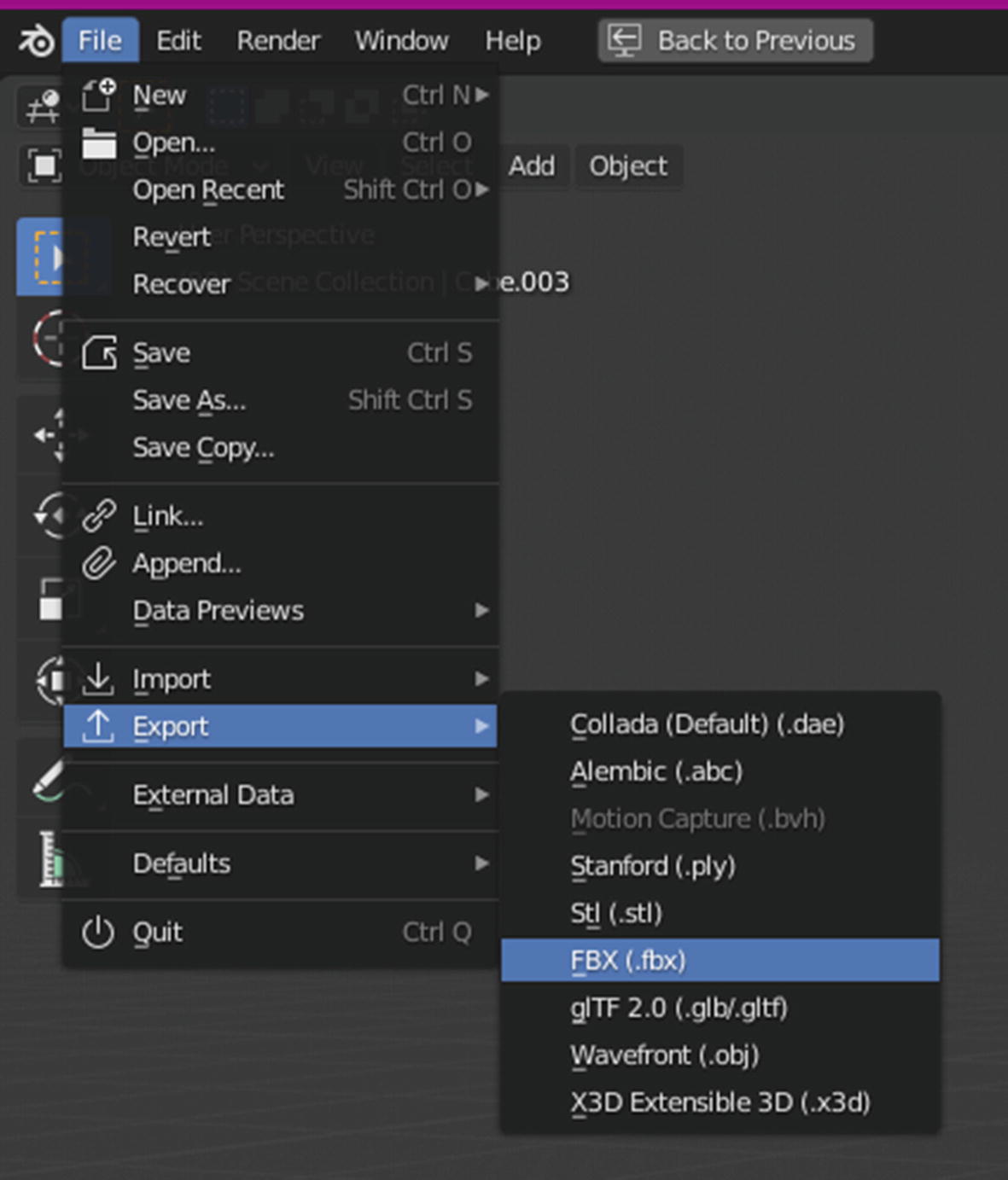
Let’s start by texturing the body of the temple. First we will see how to export assets from Blender to Substance and how to set everything up once they are inside Substance Painter. Select the top modular piece of the temple body. Then choose File ➤ Export ➤ FBX (see Figure 7-1).
Figure 7-1
Exporting an object as FBX
A new Export Settings window will open (see Figure 7-2). In this new window, make sure to enter a proper name for your file so that it is easy to identify. Next, enable Selected Objects so that only the assets that you have selected will be exported. Finally, choose a directory where you want to export. It is good practice to keep a separate directory for Blender exports. This way the directory will be neater and files will be easier to find. Leave everything else set to the defaults.
Figure 7-2
Export window of Blender
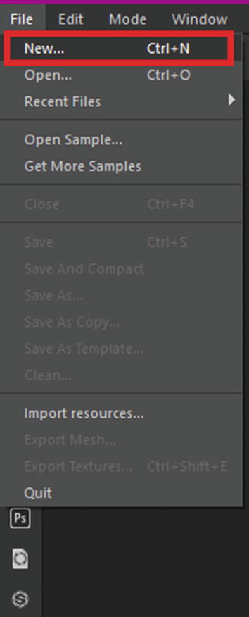
Once you are done, click on Export FBX. This will export your mesh to the destination you set. Next we are going to import this mesh into Substance Painter. Launch Substance Painter and click on File to open the File menu (see Figure 7-3). From the File menu, choose New. Alternatively you can press Ctrl+N to create a new scene.
Figure 7-3
Creating a new scene
When you click on New, a new window should open to allow you to set up the new scene and import the required assets (see Figure 7-4).
Figure 7-4
New Project window
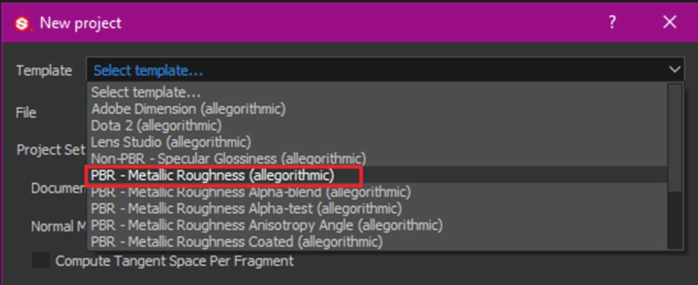
Let’s start from the top and select the template first. Click on the Template drop-down menu and choose PBR – Metallic Roughness (Allegorithmic) (see Figure 7-5).
Figure 7-5
Choosing a template
Next we will import our file. Click on the Select button just below the Template to launch the File Explorer window, which will allow you to choose a file you want to import. Choose the temple piece that we exported from the directory where it was exported (see Figure 7-6).
Figure 7-6
File Explorer window
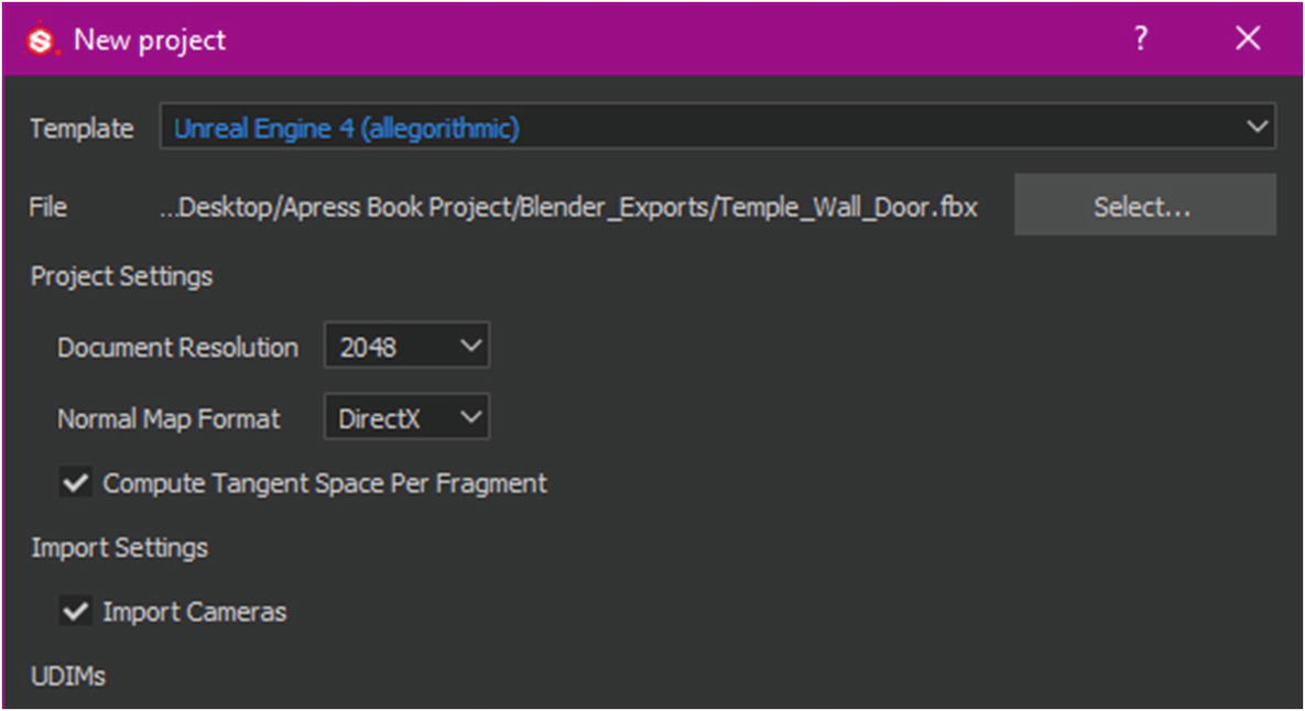
Choose your file in the File Explorer window and click on Open to import it into Substance Painter. Next, we are going to change the document resolution by clicking on the drop-down menu and setting it to 2048. Then change the Normal Map Format to DirectX, as this is the format that Unreal Engine 4 uses. You can leave the rest of the settings to the defaults. Your final settings should look like Figure 7-7.
Figure 7-7
Final settings for this project
Once you click on OK, the file will be imported and visible on your screen. We can now work on this further. But before we begin texturing, we need to do some more things. We will now see how we can bake the mesh maps. Mesh maps are used for various types of calculations and for applying procedural effects on your mesh. As soon as you import anything into Substance Painter, the first thing that you do is bake the mesh maps. To bake maps, click on Bake Mesh Maps under Texture Set Settings (see Figure 7-8).
Figure 7-8
Baking texture maps
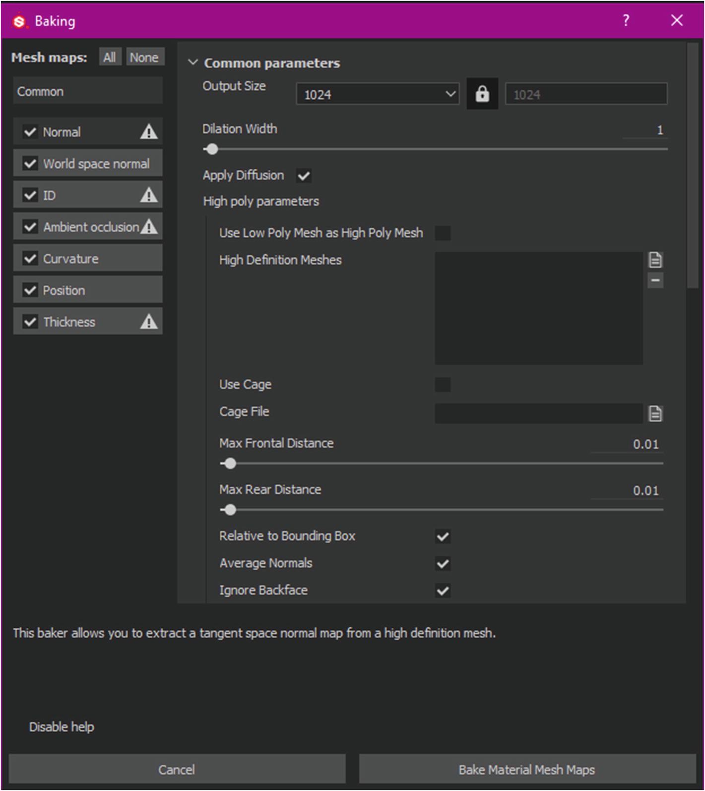
Once you click on the Bake Mesh Maps option, a new window will open, which will allow you to modify the Baking parameters (see Figure 7-9).
Figure 7-9
The Baking window
First, we will determine which maps we want to bake and which maps we don’t want to bake. In this case, we can disable the ID setting by unchecking the checkbox to the left of the map name. We disabled ID because we haven’t assigned material IDs to the object. We will also disable the Thickness baker, as we won’t be needing a thickness map and disabling it will reduce the baking time. Next, we will modify some parameters. First of all, we will increase the output size from 1024 to 2048. Next, check the Use Low Poly Mesh as High Poly Mesh option and increase anti-aliasing to 4x4 (see Figure 7-10).
Figure 7-10
Changing the appropriate parameters for the bake
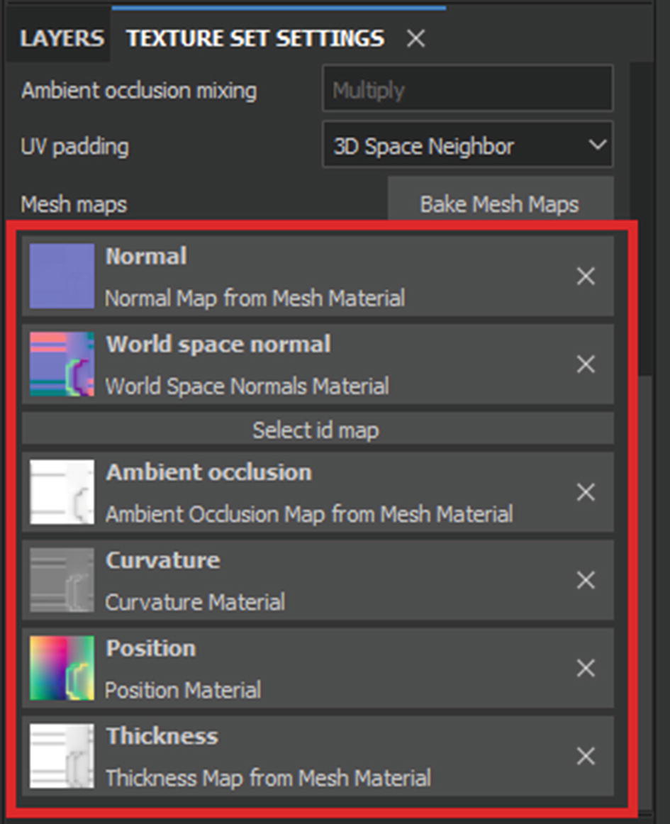
Next, click on Bake; the Substance Painter will start baking the maps. This will take some time, depending on the strength of your PC. Faster hardware will bake faster and vice versa. Once the bake finishes, you will see that the mesh maps have been automatically applied to their respective slots under Texture Set Settings, as shown in Figure 7-11.
Figure 7-11
Mesh maps in Substance Painter
Now you are ready to texture the mesh. You can start experimenting with the various materials that are shipped with Substance Painter. First, let’s see where can you get more assets. Google Substance Share and open the official website at https://share.substance3d.com/ (see Figure 7-12). Sign in using the same account that you used for downloading Substance Painter.
Figure 7-12
Substance Share website
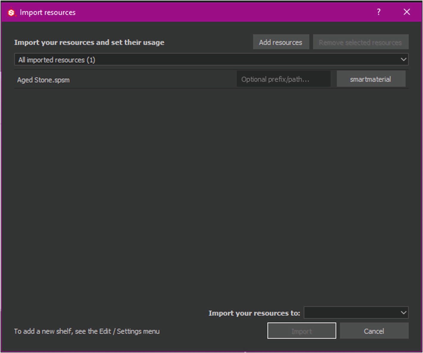
While you are there, use the search bar to search for some materials that can be used for temples, such as smooth rocks or bricks. See the reference to identify which materials will be suitable. I personally found the Aged Stone material quite interesting and we will repurpose it for use in this example. Download it (or any other material) by simply clicking on the Download button. Once the material is downloaded, it will normally be in a compressed archive. Extract it to a suitable destination. Then drag and drop the .spsm file into the Content Browser of Substance Painter to open the Import Resources dialog box.
Figure 7-13
Import Resources dialog box
Based on the file type, Substance Painter automatically assigns the material a type. In this case, it is Smart Material. Next, you need to determine where you want the resource to be imported. Use the Import Your Resources To drop-down menu to set where to import your resource. There are three options: current session, project [project name], and shelf “shelf.” Each will result in different outcomes.
Current Session will import the asset and will keep it only as long as you are working on the session. As soon as you close the session, the asset will be deleted.
Importing it to Project will keep it only for the project you are currently working on. When you create a new project, it won’t be there. This can help reduce clutter.
Shelf will import the asset permanently into your shelf and it will stay there for every session that you create. This allows you to use this asset in any number of projects.
In this case, import the resource to shelf, as shown in Figure 7-14.
Figure 7-14
Importing assets into the shelf
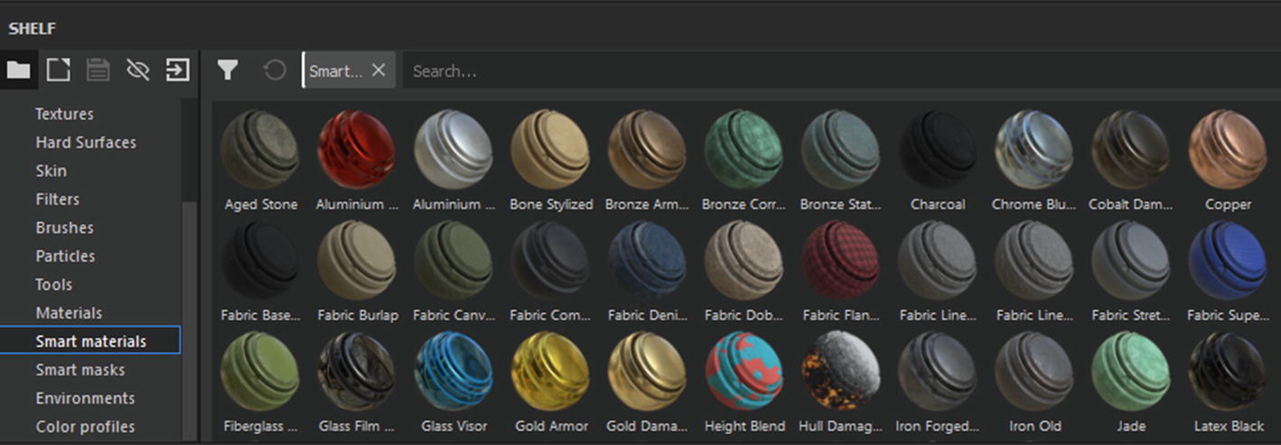
We will be using the downloaded materials for nearly all our assets, so it is better if we import the asset into the shelf. This way, we won’t have to keep importing it every time we create a new project. Once this is done, click on Import Your Assets(s) into Substance Painter’s shelf. You will find the assets in their respective shelf type. Our asset was a Smart Material, so you can access it by clicking on the Smart Materials tab in the shelf. Materials and Smart Materials are very different from each other. We will explore the differences in detail as we work. For now, click on the Smart Materials tab to display all the Smart Materials that you have currently installed (see Figure 7-15). By default, Substance Painter ships with more than 100 Smart Materials, which is very useful.
Figure 7-15
The Smart Materials tab of Substance Painter
Scroll down to locate the asset that you downloaded. Let’s apply that to the model. Drag the Smart Material from the shelf and drop it on the model. You will see that the asset becomes textured. Let’s now take a quick look at the Layers and Layer Properties tabs. The Layers tab shows any materials, masks, and filters you applied to your mesh in the order they were applied, as shown in Figure 7-16.
Figure 7-16
The Layers window
Just below the Layers window is the Layer Properties window, which shows the editable parameters of the selected layer. You can modify these to change the effect the parameter has on your model (see Figure 7-17).
Figure 7-17
The Layer Properties window
We will explore all the effects in more detail as we texture our assets. As for now, I highly suggest that you play with the values and experiment to see what does what and what you can come up with. This may seem like there is lot to digest, but as you work more with Substance Painter, you will realize that it is not that complicated after all.
Texturing the Larger Structures
Let’s begin texturing now. We have already applied a Smart Material to the first asset, which is the top part of the temple modular piece. Since we are not going to use Substance Designer to create our own materials, we will depend on materials that can be downloaded or that ship with Substance Painter. Mostly we have to download materials to get the result that we want. So look on the Internet.
We will now see the difference between a material and a Smart Material. This is best understood with an example. Here is a short explanation first.
A material is created inside Substance Designer using nodes and graphs. When they are imported into Painter, they work as materials that can be applied to any mesh. How modifiable the material is depends on the parameters exposed by its creator. Otherwise, the material will just do its job of applying the texture data to the mesh, without many modifications available.
A Smart Material, on the other hand, is created by stacking layers and effects to create a material. Every layer is modifiable and the effect can be changed to make the material the way you want it. This also makes modifying them more complicated. All effects in a Smart Material will automatically adapt according to the mesh on which it is applied, hence it is called a Smart Material.
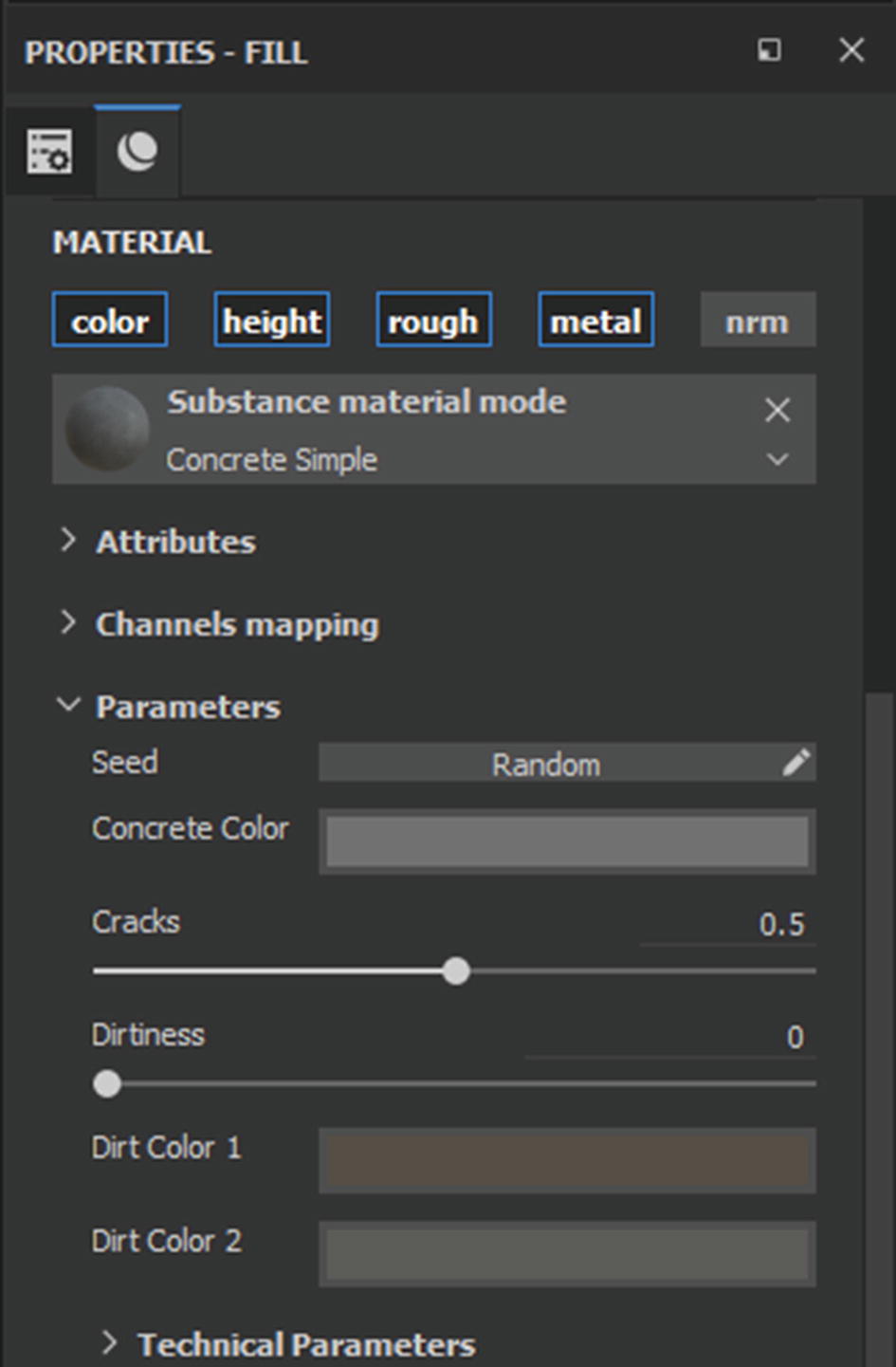
Let’s now see the examples of both. We will first apply a material to the object. Any material will do, as we are just trying the basics now. So choose any material from the shelf and drag and drop it on to the mesh or on to the layer stack (the effect will be same). Once it’s applied, you will see the editable material parameters in the Layer Properties window. If you scroll down, you will see some parameters that you can edit to modify the material, but it will usually not be much. The modifications are limited (see Figure 7-18).
Figure 7-18
Material properties to modify their look
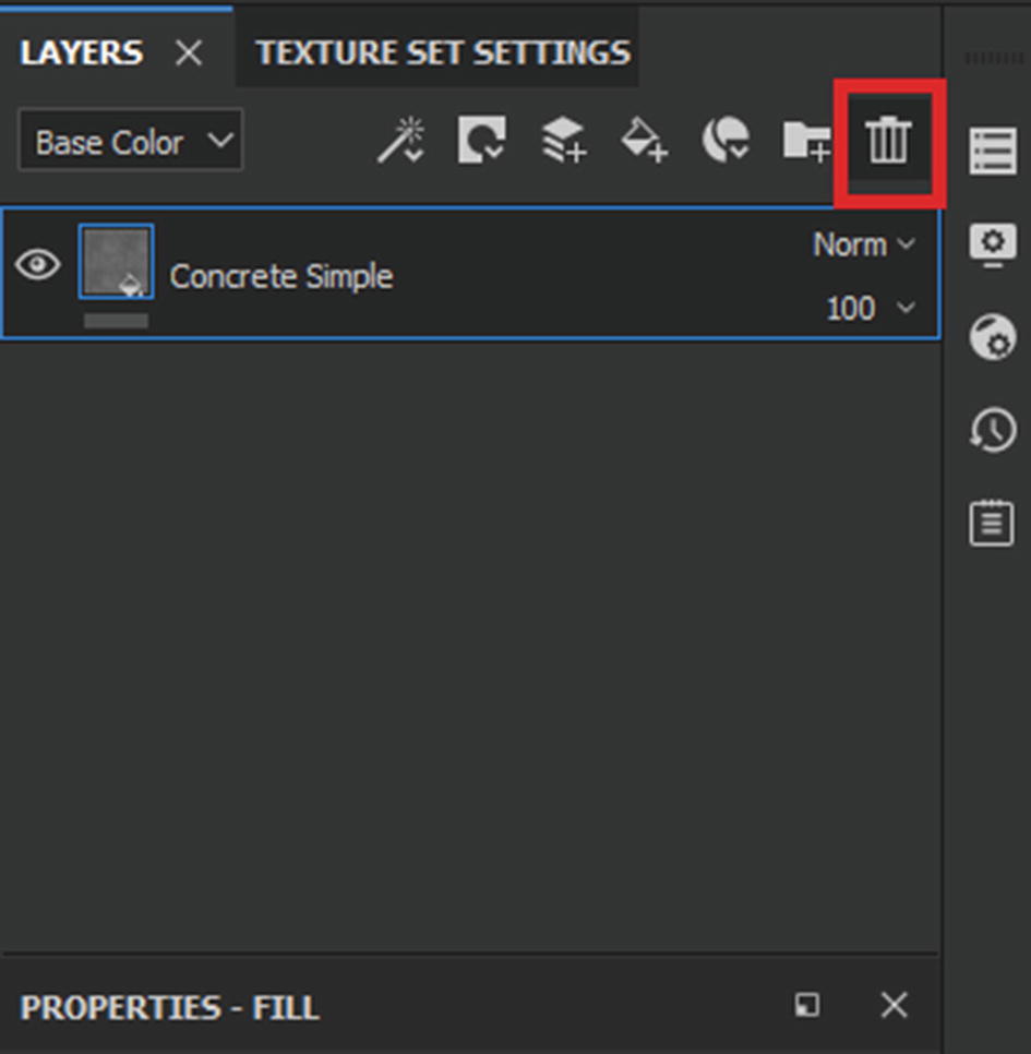
As you can see in the Concrete Simple material, there are a couple of settings (Cracks and Dirtiness) that can be modified to alter the amount of dirt and cracks in the material. Next, let’s play with Smart Materials and see what options we have for them. Select the material from the Layer Stack and click on the Delete icon to delete it (see Figure 7-19).
Figure 7-19
Deleting the selected layer
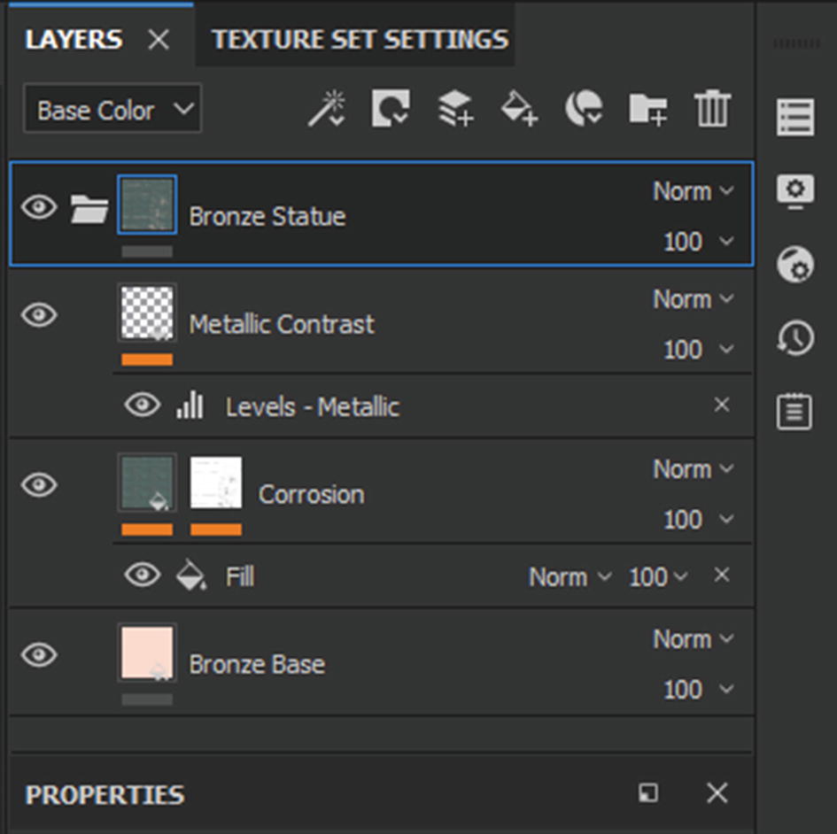
Now switch to the Smart Materials tab. Apply the Smart Material of your choice to the mesh. In this case, I apply the Bronze Statue Smart Material to the mesh. Once you apply a Smart Material, you will see that, instead of a single material layer, it’s a folder that consists of several layers as well as some procedural effects that have been stacked together to create the final material (see Figure 7-20).
Figure 7-20
Layers and effects stacked to form a Smart Material
As you can see, there is a lot that can be changed to modify the look of the Smart Material, but it is also very complex and unintuitive. In this project, we will create our own Smart Material by stacking together several layers. That way, we can apply the same material to the whole temple without having to re-create the material every time we texture a new asset. Let’s delete this Smart Material from the layer stack by selecting the folder that houses the Smart Material and deleting it
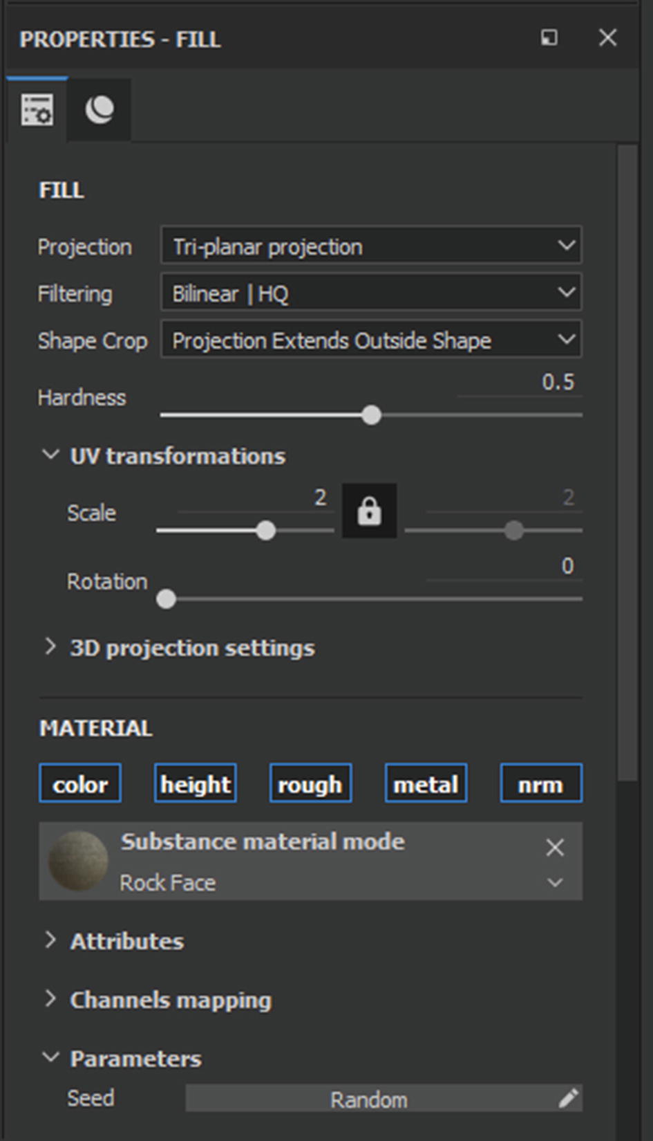
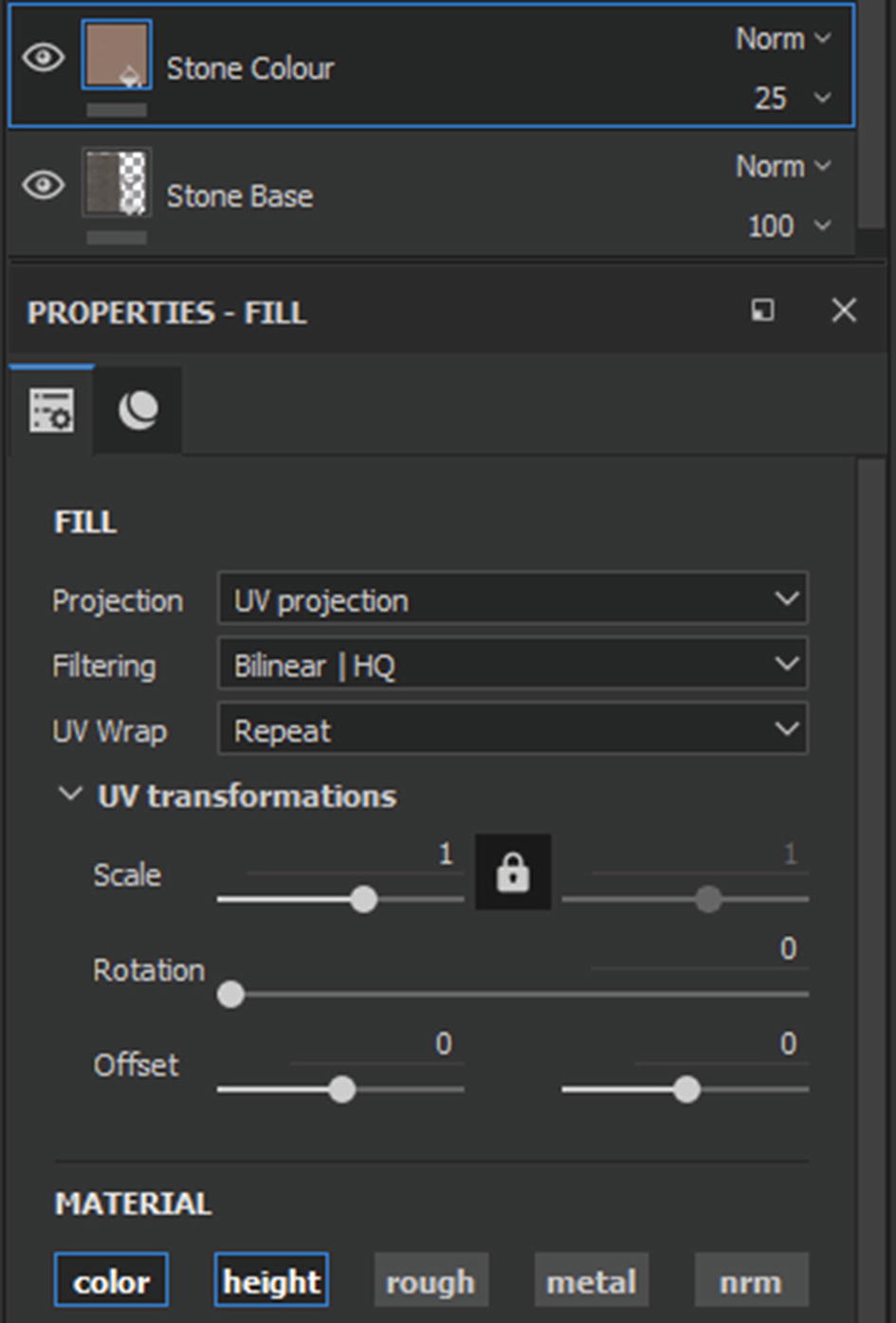
We can now start the texturing process. First we will need a stone material that will form the base for the material. In this case, I drag and drop a limestone asset that I found on Substance Source. You can either drop your material directly on the mesh or drop it in the layer stack. Either way, your model will be textured and the material properties will show up in the Properties window. You can also modify certain settings. The first thing that you can change is the texture projection type. By default, it is set to UV Projection. Click on the Projection drop-down menu and change it to Tri-Planer Projection (see Figure 7-21). Check out the difference that it makes. Pick the one that one looks better to you.
Figure 7-21
Changing the texture projection type of the material
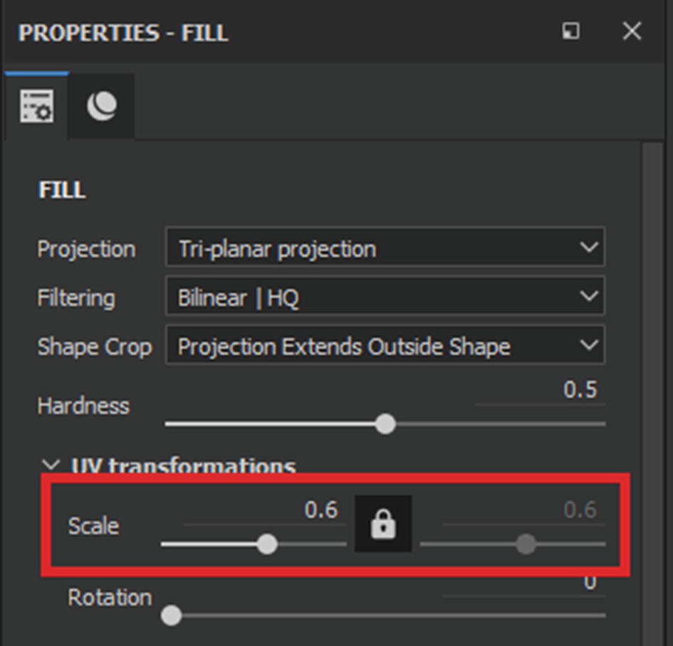
There are a lot of options that you can change. Let’s now move on to UV Transformations. You can change the tiling of the material by modifying the Scale value (see Figure 7-22).
Figure 7-22
Changing the tiling of the material
Try increasing and decreasing the scale to find a suitable value that you like. You will notice that when you change the Projection to Tri-Planar Projection, the texture suddenly starts appearing more tiled. When you switch back to UV Projection, the texture will appear less tiled (in other words, it will be scaled down). So keep that in mind when changing your projection type.
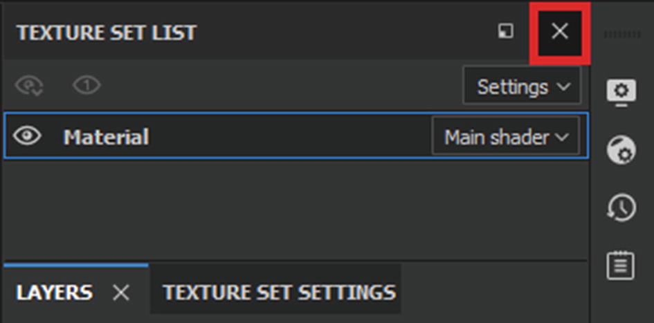
Close the Texture Set List window because we won’t be using it and it is occupying space unnecessarily (see Figure 7-23).
Figure 7-23
Closing the Texture Set List window
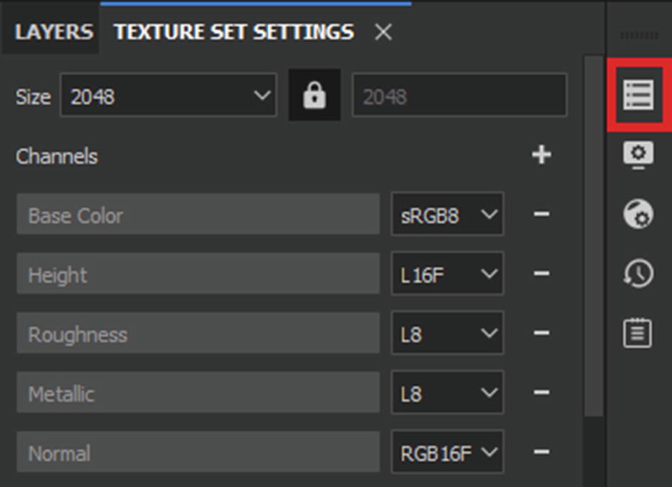
When you close it, you will see its icon appear on the right side of the window; you can open it anytime by clicking on the icon (see Figure 7-24).
Figure 7-24
Minimized Texture Set List icon
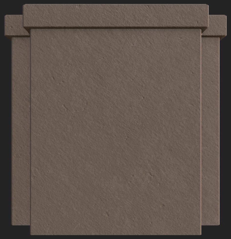
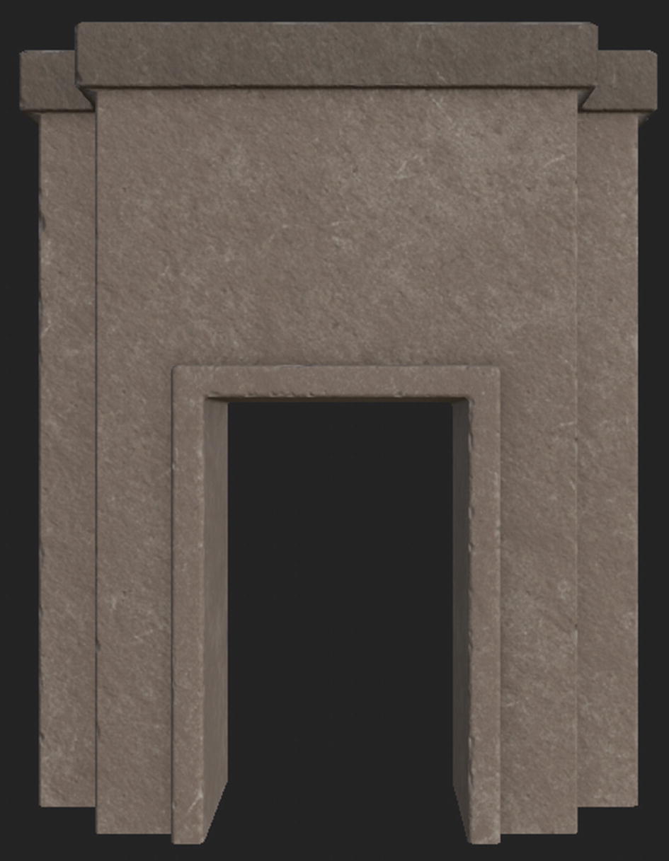
You can extend the important windows so that you have more room to work with them. So let’s proceed with texturing. In Figure 7-25, you can see the current result of the material applied to the mesh. You should try to achieve a similar result. With downloaded materials, you might not get exactly what you want, so it may be hard to make something that looks exactly similar.
Figure 7-25
Result of texturing so far
You have created the base for the texture, so it’s time to stack some more details on top of it to get the result that you want. Let’s get a sandstone material and apply it to the top of the previous material. This material should be on top of your previous material in the layer stack. This layer will provide the primary rough sandy color to the mesh. In the Layer Properties window, scroll down and find the active channels. Disable the Rough and Metal channels by clicking on them, as shown in Figure 7-26.
Figure 7-26
Material channels active/inactive
Active material channels are shown highlighted in blue, while the disabled channels are grayed out. Your setup should look similar to Figure 7-27.
Figure 7-27
Setup of the materials
Next, let’s see how the material looks. Your outcome should be something similar to, if not the same as, Figure 7-28.
Figure 7-28
Result so far
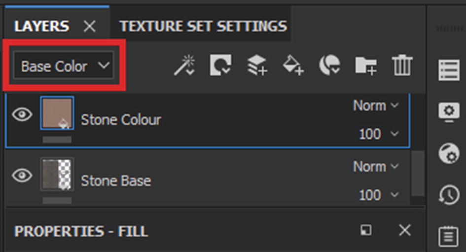
Next, let’s tone down the transparency of the color layer so that some of the details from the layer below it are visible as well. First make sure that you are in the Base Color mode in the Layer Stack window (see Figure 7-29).
Figure 7-29
Texture mode of the layer
If you are in Base Color, then proceed; otherwise, click on the drop-down menu highlighted in Figure 7-29 and switch to Base Color. Next, we will reduce the transparency by using the transparency slider (see Figure 7-30) and tone down the transparency to something between 30-50 (or whatever looks good to you).
Figure 7-30
Transparency slider
When you reduce the transparency of the material, the material below it will start showing on the mesh. Your output should be similar to Figure 7-31.
Figure 7-31
Result so far
As you can see in Figure 7-31, when we reduce the transparency of the color layer, lots of the damage and color clusters present in the layer below become visible. This will give it a better look than one clean material. The color patterns from the layer below break the flatness of the uniform color and give it a more natural, weathered look.
Next we are going to add another Fill layer to the layer stack by clicking on the Add Fill Layer icon (see Figure 7-32).
Figure 7-32
Add Fill Layer icon
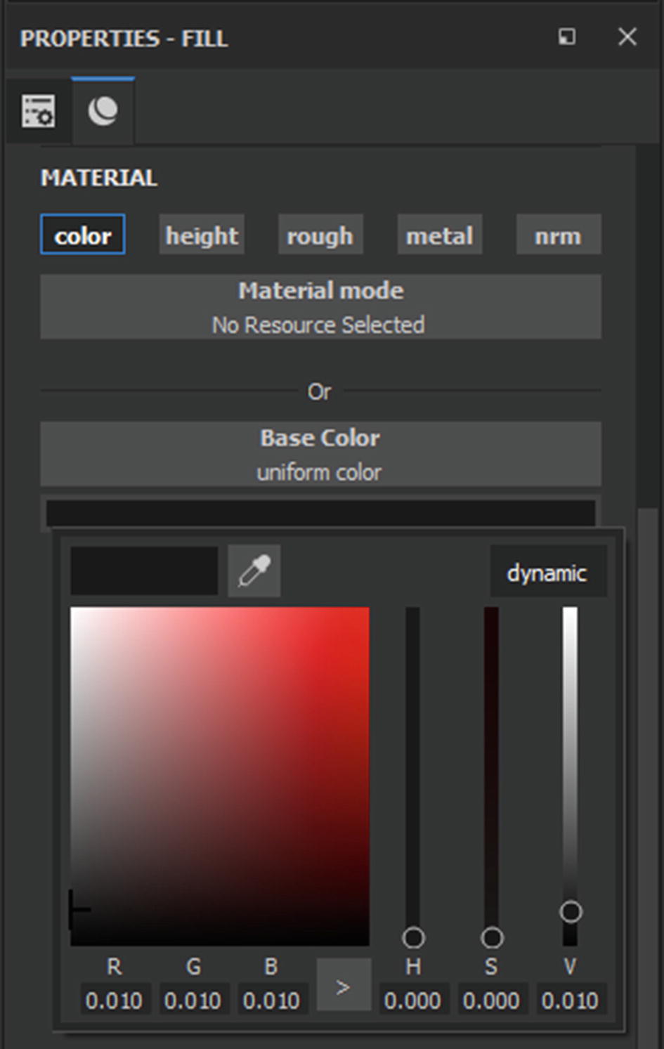
Your new fill layer will be added and you will see its effect immediately on your mesh. A fill layer will be created with the default fill settings. You can see those settings by scrolling down in the Layer Properties window under the Material category. Here, we will change a few things. First, we will disable all channels except Base Color. Then we will change the base color to a deep gray color, as shown in Figure 7-33.
Figure 7-33
Setting the color of the fill layer
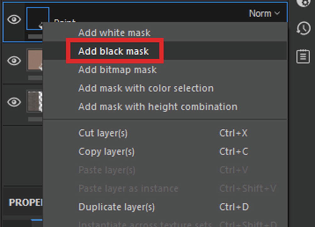
As you can see, the fill layer currently affects the whole mesh. But we want to limit its influence only on the extruded part. For that, we will use a mask. A mask is a grayscale texture that determines the transparency of the object/texture on which it is applied. Black represents completely transparent or invisible, while white represents completely opaque or visible. Black regions will not contain the masked texture, while white regions will. Right-click on the fill layer that you created and choose Add Black Mask from the list (see Figure 7-34).
Figure 7-34
Adding black mask to our layer
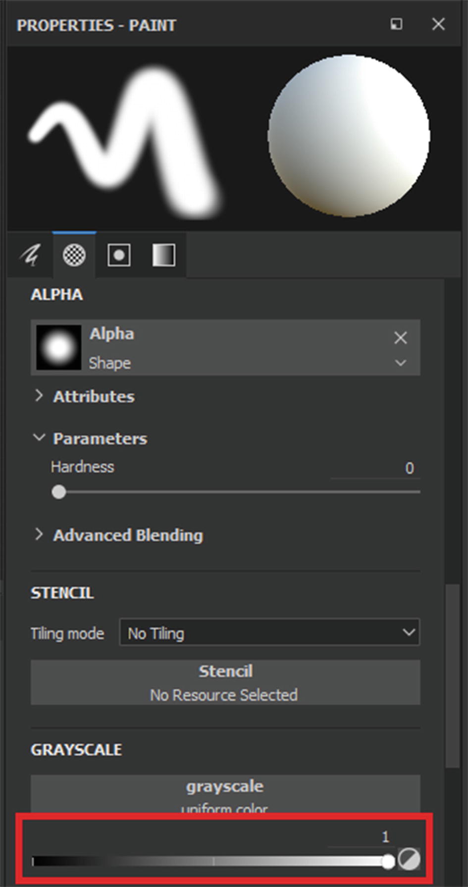
You will immediately see that the effect of the fill layer disappears. The black mask has made everything in the layer completely transparent. Now, with the mask selected, view the Properties window. You will see mask-related settings on it now (see Figure 7-35). You can paint in or out the areas that you want to be affected by the mask. There are several ways to do this. First, ensure that the Grayscale slider is set all the way to white, as shown in Figure 7-35.
Figure 7-35
Mask settings
Now try painting on your mesh and see what happens. If you have set your Grayscale slider all the way to white, you will see that wherever you paint, the information from the paint layer starts showing up. To remove paint information, simply bring the Grayscale slider all the way back to black. Then when you paint you will be removing the painted information of the layer.
Next, let’s learn about a more accurate way of editing the mask. We will use Polygon Selection tool to select which polygons we want our mask to affect. This way we don’t have to manually paint the mask and worry about inconsistencies.
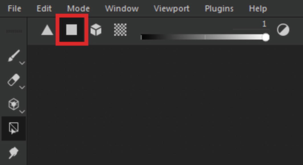
First, turn on the Polygon Selection tool while the mask is selected (see Figure 7-36).
Figure 7-36
Polygon Fill tool
When you activate the Polygon Fill tool, you will see more settings related to it pop up in the horizontal bar, as shown in Figure 7-37.
Figure 7-37
Tool settings
From left to right, the Polygon Fill tool options are:
Triangle Fill: This fills the triangle present in the mesh.
Polygon Fill: This fills an entire polygon at a time.
Mesh Fill: This fills an entire connected mesh at a time.
UV Chunk Fill: This fills all the faces that are contained in a single UV island.
Color Selection: Using this you can change which color to fill. You can choose between grayscale values and black and white.
Invert Value: This simply inverts the color value of the Color Selection tool.
Symmetry: This toggles the symmetry, allowing you to make edits to one side and the edits will automatically carry over to the mirrored, opposite side.
Click on the Polygon Fill icon highlighted in Figure 7-38.
Figure 7-38
Polygon Fill tool
Once the tool is selected, your mesh will highlight all the selectable polygons. The wireframe on your mesh will help you identify what is selectable and what isn’t (see Figure 7-39).
Figure 7-39
Wireframe showing selectable polygons
Try clicking on your mesh and you will see the material present on the layer. It will start appearing anywhere you click as long as the mask color is set to white. The opposite is also true; if your color is set to black, the paint information of the layer will disappear from any region where you click.
Try drawing a selection box by clicking, holding, and dragging. This will allow you to select a wider area where you want to apply the paint information of the layer. So let’s use this information to apply the dark paint color to the extruded region of our mesh.
First make sure that the mask called Color Selection in the mask settings is set all the way to white; then draw a selection box similar to what is shown in the Figure 7-40. This will select the entire top region.
Figure 7-40
Selecting using selection box
Remember that this works for everything that is within the box. It does not matter whether it’s visible or not, or behind some other mesh. So every face within this selection box will be selected regardless of its location and visibility. You will immediately notice that the layer’s paint information is applied to all the faces.
Next, select the faces not to be affected by the paint layer. Set the color selection slider all the way to black and draw a selection box similar to Figure 7-41.
Figure 7-41
Selecting the faces that you don’t want painted
Now you have painted the mesh in two different colors. This gives the mesh some variation. You can set any color you want for this piece; that’s entirely your choice.
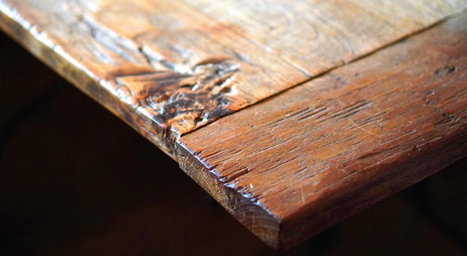
Next you need to add some more variation to this in the form of edge damage. If you check the edge of any real-world object, be it a table, box, wall, closet, etc., you will notice that most of the wear and tear happens on the edges of these objects (see Figure 7-42). This is probably because it is most exposed and the material is thinnest there.
Figure 7-42 clearly shows edge wear on the edges of the table. This is a natural phenomenon. To add some realism to these textures, we will add some wear in Substance Painter.
So, the first thing that you need to do is create a new Fill layer just like we created before, by clicking on its icon. Disable all the channels except Color and Height. Set the color to a whitish gray, more on the whiter side, and set the height channel to -0.5. Your settings should look similar to Figure 7-43.
Figure 7-43
Material settings for the edge wear layer
As you can see, this fills up your whole object with the data on this layer. Right now, it may be hard to see what exactly the height channel is doing because it is working on the entire object and thus its effect is not comprehensible.
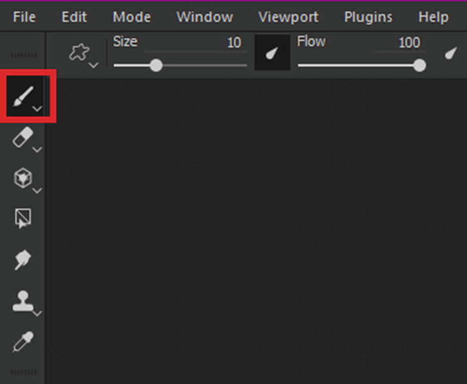
So, to see what is going on, we are going to add a black mask to this layer. You can do this by right-clicking on the layer in the layer stack. After adding the black mask, select the Brush tool in case you still have the Polygon Fill tool selected from the last session. To select the brush, click on its icon, which is highlighted in Figure 7-44.
Figure 7-44
Brush tool
Next, make sure that the color selection in the mask properties is set all the way to white and paint a few strokes on your mesh. You should have a result similar to Figure 7-45 if you have done everything right.
Figure 7-45
Effect of the fill layer
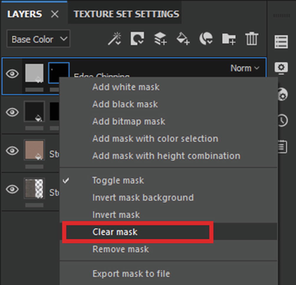
As you can see in Figure 7-45, the paint strokes seem to dig into the mesh. This is exactly what we need. Remove the strokes by right-clicking on the mask and choosing Clear Mask (see Figure 7-46). This will reset the mask back to completely black.
Figure 7-46
Clearing the mask
Now we will use a generator to procedurally create edge wear. In order to add a generator, you need to click on your mask container on the layer and then right-click after it is selected to open a menu related to the mask. Toward the bottom of this menu, you will find the Add Generator option (see Figure 7-47). Click on OK to add a generator to your mask.
Figure 7-47
Adding a generator to the texture
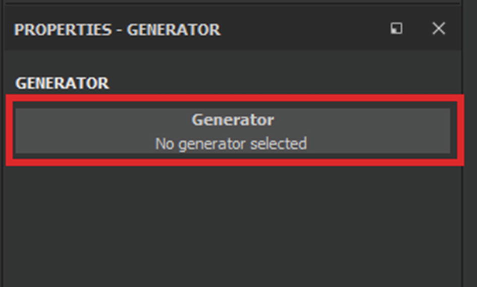
Once the generator is added, you will see an empty generator slot in the Properties window (see Figure 7-48).
Figure 7-48
Empty generator field/slot
If you click on it, a new window will pop up giving you a menu of several generators that you can use for your work. Choose Mask Editor from this window (see Figure 7-49).
Figure 7-49
Generator list
When you add this generator, you will see that the Properties window will transform and all the parameters related to the Mask Editor generator will appear (see Figure 7-50). This new list of parameters will be large and daunting at first. But it gives you lots of control. For the purposes here, we will use only a few of them.
Figure 7-50
Generator settings
We now need to edit this generator to procedurally create the edge chipping. To do that, scroll down the Properties window where it says Image Inputs (see Figure 7-51).
Figure 7-51
Image input fields
Click on the empty field that says Texture Uniform Color to open a new mini window. It will show a list of image inputs that you can apply to this field. In the search bar highlighted in Figure 7-52, type concrete next to procedural,texture.
Figure 7-52
Image picker window
All the concrete grunge maps will appear when you type concrete in the search bar. Choose one from the list, the effect is mostly similar. Once you’ve applied the map, you will see something happening to the edges of your mesh. This will depend on your default settings, but we will tweak the values ourselves.
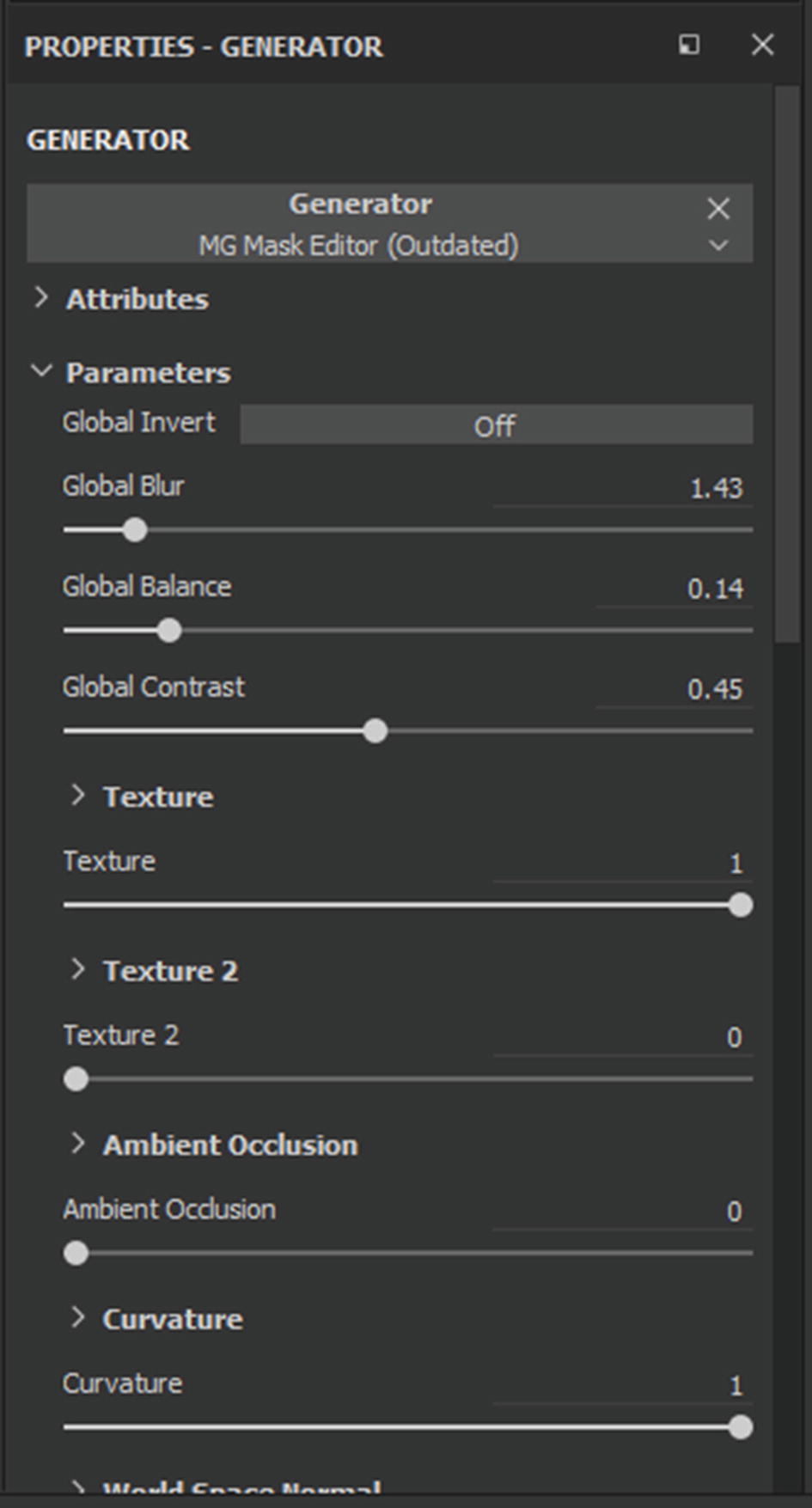
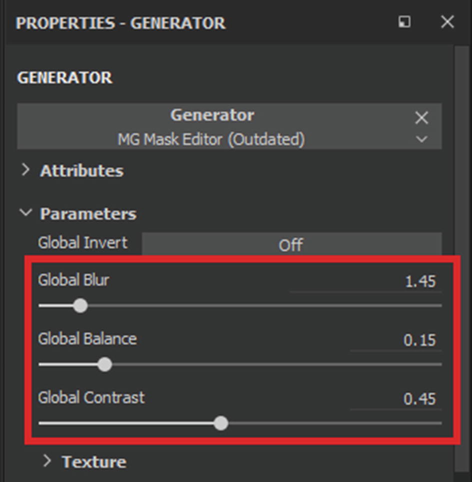
Scroll up to the top of the Properties window (see Figure 7-53) and change the following settings:
1.
Set Global Blur to 1.45.
2.
Set Global Balance to 0.15.
3.
Set Global Contrast to 0.45.
Figure 7-53
Modifying the parameters
You can also change the values according to the final result that you want. Finally, reduce the opacity of the layer to control the amount of color you want. You can also disable the color channel altogether if you want.
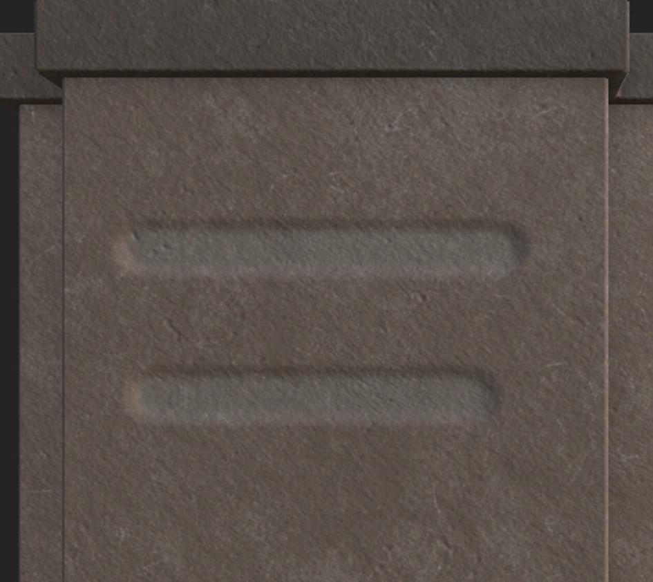
If you have done everything correctly, your current result should look something similar to Figure 7-54.
Figure 7-54
Result so far
You have now created edge damage using procedural generators. This adds another layer of realism to the mesh. Let’s next see how you can create a Smart Material that can be reused on different meshes so that your work time and effort is reduced.
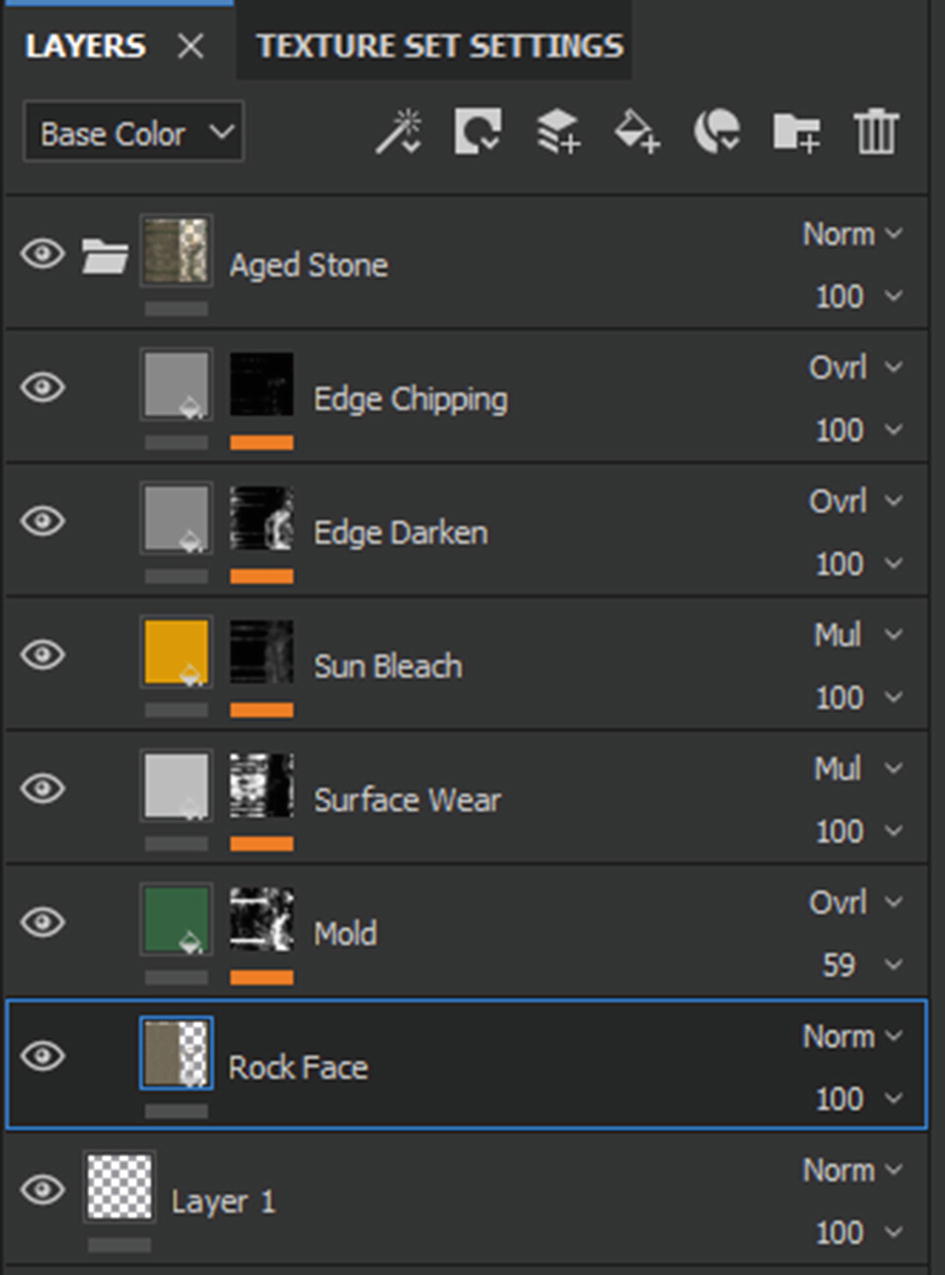
Start by creating a new folder by clicking on the Create Folder icon (see Figure 7-55). This will add an empty folder to your layer stack.
Figure 7-55
Creating a new folder
Select all your layers by Ctrl+clicking on them, then drag and drop them inside the new folder. Then double-click on the name of the folder so you can rename it (see Figure 7-56).
Figure 7-56
Renaming the layer
Give your layer a proper name, as the name of this layer will become the name of the Smart Material. In this case, I named it Temple Material.
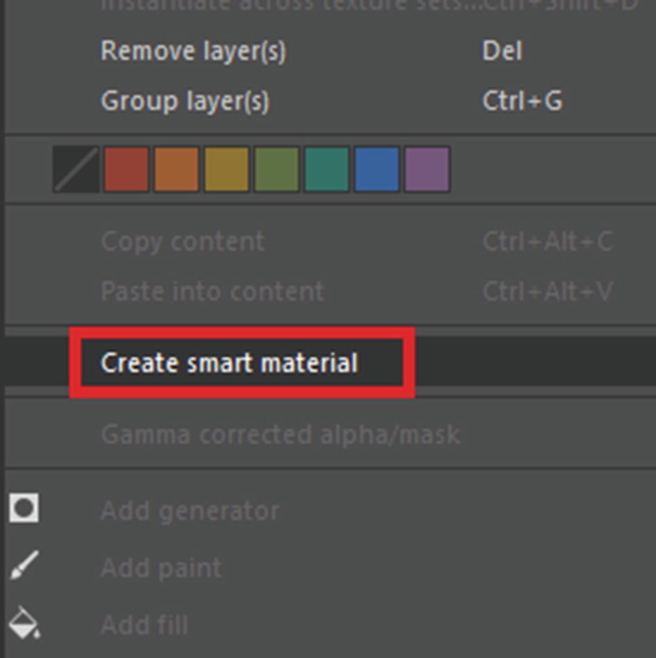
Next, right-click the folder and choose Create Smart Material (see Figure 7-56). This will create a Smart Material with same name as the folder.
Figure 7-57
Creating a Smart Material
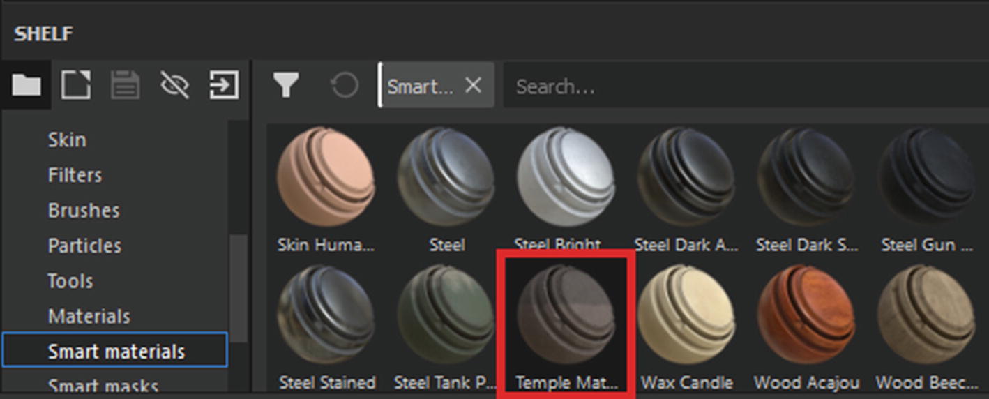
You will now be able to find this Smart Material in the Smart Materials tab of the Substance Painter “shelf” (see Figure 7-58).
Figure 7-58
The Smart Material in the shelf
So the Smart Material is now in the shelf, ready to be applied to any mesh that you import into Painter. This material is adaptive and will automatically align itself to the topology of the imported mesh. The only thing that will not adapt to topology is the painting that we did to darken a specific part of the temple piece. But we still decided to include it. You can easily modify it or simply disable or remove it.
With that, we wrap up the texturing basics. We will now quickly texture the rest of the assets.
Texturing the Remaining Assets Using Smart Materials
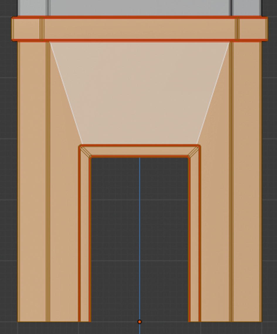
Let’s export another asset from Blender. This time it will be the bottom wall of the main temple body (see Figure 7-59).
Figure 7-59
The next asset to be textured
Import it into Substance Painter, but this time we are going to change the import preset. Switch the preset from PBR Metallic Rough to Unreal Engine 4. Also check the Compute Tangent Space per Fragment option if it’s not checked automatically. See Figure 7-60.
Figure 7-60
New preset for this project
Click on the Import button to import the mesh in Substance Painter. Bake the materials again, like you did before. This time, disable the ID and Thickness maps. Bake using the same settings that you used before. After the bake is complete, drag and drop the Smart Material that we created on the mesh. Your result may or may not be similar to Figure 7-61.
Figure 7-61
Current result
As you can see in Figure 7-61, the color is being mapped incorrectly. You might not have a similar problem, depending on many factors. But any problem like this can be fixed very easily. All you need to do is that edit the mask of the Paint layer.
Select the mask and then go to the Polygon Fill tool. With the mask color set to black, click on the wrongly colored polygon to clear the color. If any area does not have correct color, then adjust the mask and use the Polygon Fill tool to fill it in accordingly.
If you find the tiling is incorrect or the cracks are too large or small, there is way to fix them as well. Let’s tackle this one by one.
1.
First you will fix the tiling on the grainy stone material. To do this, select the layer that has the material. Go to Layer properties and change the Projection option to Tri-Planar Projection and increase the Scale to 2 (see Figure 7-62).
Figure 7-62
Modifying the layer’s parameters
2.
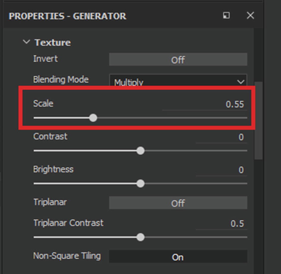
Next you are going to modify the tiling of the edge damage layer. Select the mask that contains the generator and click on the generator in the layer stack. Options related to it should appear in the Properties window. Scroll down until you see a collapsed category called Texture. Expand it by clicking on the arrow next to it. You should see the Scale parameter under it. Increase the scale until you are happy with the result of the cracks generated. See Figure 7-63.
Figure 7-63
Changing the scale of the texture used in the generator
Hopefully you have the result that you want. You can modify the material in any way from this point. It is important to always have a reference so you can see what you want to achieve. Current results so far are shown in Figure 7-64. You can certainly try to achieve a result similar to it.
Figure 7-64
Results so far
Next, we are going to add carving details to the mesh. But before we do that, we will need alpha maps with carving information. In the previous chapters, we mentioned websites for getting such things. Look around until you find something good. In the next chapter, we will create game-ready foliage like grasses, bushes, and trees.