
The reference architecture shown in Figure 5-1 is an evolution of the abstract Web 2.0 model discussed in Chapter 4, with more detail added for developers and architects to consider during implementation. Each layer can contain many components, but at the top level of abstraction, they provide a foundation that applies to many different kinds of application.
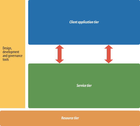
The components of this architecture are:
- Resource tier
The bottommost tier is the resource tier, which includes capabilities or backend systems that can support services that will be consumed over the Internet: that is, the data or processing needed for creating a rich user experience. This typically includes files; databases; enterprise resource planning (ERP) and customer relationship management (CRM) systems; directories; and other common applications an enterprise, site, or individual may have within its domain.
- Service tier
The service tier connects to the resource tier and packages functionality so that it may be accessed as a service, giving the service provider control over what goes in and out. Within enterprises, the classic examples of this functionality are J2EE application servers deploying SOAP or EJB endpoints. Web developers may be more familiar with PHP, Rails, ASP, and a wide variety of other frameworks for connecting resources to the Web.
- Connectivity
Connectivity is the means of reaching a service. For any service to be consumed, it must be visible to and reachable by the service consumer. It must be possible for potential service consumers to understand what the service does in terms of both business and technical consequences. Connectivity is largely handled using standards and protocols such as XML over HTTP, but other formats and protocols are also possible.
- Client tier
Client-tier software helps users to consume services and displays graphical views of service calls to users. Examples of client-side implementations include web browsers, Adobe Flash Player, Microsoft Silverlight, Acrobat, iTunes, and many more.
- Design, development, and governance tools
This section encompasses the set of tools that enables designers and developers to build web applications. Typically, these tools offer them views into both the client and service tiers. Examples include Adobe Dreamweaver and Apple’s developer tools xCode and DashCode, though there are many integrated development environments (IDEs) out there, and many developers have their own custom sets of tools.
Each of these tiers can contain a wide variety of components. Figure 5-2 shows many more possibilities in greater detail. (Tools come in so many forms that it’s not easily broken down.)
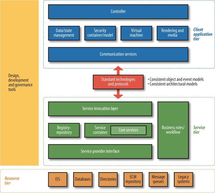
Figure 5-2. Detailed reference architecture for Web 2.0 application architects and developers (special thanks to Nabeel Al-Sharma, Dan Heick, Marcel Boucher, Laurel Reitman, Kevin Lynch, and Michele Turner for help developing this model)
This Web 2.0 Reference Architecture is very general, but it fulfills a purpose similar to that of the residential dwelling reference architecture discussed earlier. It should not be considered “the” sole authoritative Web 2.0 Reference Architecture. It is meant as a reference architecture that decomposes each of the concepts in Figure 5-1 into more detail. Software architects or businesspeople can use it as a starting point when designing a way to implement a certain set of design or architectural patterns over the Internet. It lets those people ask important questions that will be relevant to their purposes, such as “What type of client application do we need?” or “Where are we going to authenticate users?”
The Web 2.0 Reference Architecture is not tied to any specific technologies or standards nor is it dependent upon them. Architects and entrepreneurs can decide how to implement this reference architecture using standards and technologies specific to their needs. For example, if services need to be reachable by and visible to the largest possible segment of users, they may choose a protocol such as HTTP for its simplicity, its ability to pass through most corporate firewalls, and its widespread adoption. They could also opt for other messaging protocols to meet special requirements, such as Web Services Reliable Exchange (WS-RX) for reliable messaging, Web Services Secure Exchange (WS-SX) for enhanced security and efficiency with security, or BitTorrent for rapid distribution of multimedia content.
One last thing to note is that software implementations may choose to use all, some, or none of the individual components in each of the tiers. Figure 5-2 is based on a commonly used set of components to enable the patterns described in Chapter 7, but there are many simpler and more complex components that could be included.
This tier contains core functionality and capabilities and can be implemented in many ways depending upon the context. For example, a large enterprise might have an ERP system, an employees directory, a CRM system, and several other systems that can be leveraged and made available as services via the service tier. A smaller example might be an individual cell phone with a simple collection of vCards (electronic business cards), which are also resources and can also be made available as a service to be consumed, perhaps over a Bluetooth connection. Figure 5-3 shows a fairly complex enterprise resource tier.

The resource tier is increasingly being integrated into web applications in order to build rich user experiences. As client-side applications become richer and software rises above the level of any one piece of hardware (or device), making small computational pieces available to the client tier becomes a tangible requirement for many resource owners. This manifests as software that is no longer tied to specific operating systems or even, with large enterprise systems, operating in the cloud.
While these inner boxes are meant only as exemplars of potential resources, we’ll look at each in detail to help you understand the overall architecture and some common capabilities:
- EIS
Enterprise Information System (EIS) is an abstract moniker for a component common in most IT systems. EISs typically hold various types of data for use by those who run the company. An example might be a short-term storage database or sensors feeding information into a common repository.
- Databases
Databases are typically used to persist data in a centralized repository designed in compliance with a relational model. Other types include hierarchal databases and native XML databases. Each type of database is tasked with handling centralized persistence of data that may be retrieved later for a variety of purposes. Databases vary in size and complexity based on the amount and nature of the data stored, and may be supplemented by classic filesystems or other data-storage mechanisms.
- Directories
Directories are lookup mechanisms that persist and maintain records containing information about users. Such records may include additional details for authentication or even business data pertaining to their purpose. Using a centralized directory is a good architectural practice to avoid errors arising from mismatches in the state of any one person’s records. Examples of this are LDAP-based systems and Microsoft’s Active Directory.
- ECM repository
Enterprise content management (ECM) repositories are specialized types of EIS and database systems. While they typically use databases for long-term persistence, most ECM systems are free to use multiple data-persistence mechanisms, all managed by a centralized interface. ECM systems are often used for long-term storage and have several common features related to the various tasks and workflows enterprises have with respect to data management.
- Message queues
Message queues are ordered lists of messages for inter-component communications within many enterprises. Messages are passed via an asynchronous communications protocol, meaning that the message’s sender and receiver do not need to interact with the message queue at the same time. Typically, messages are used for interprocess communication or inter-thread communication to deal with internal workflows; however, in recent years the advent of web services has allowed enterprises to tie these into their service tiers for inter-enterprise communication. Popular implementations of this functionality include JMS, IBM’s WebSphere MQ (formerly MQSeries), and, more recently, Amazon’s Simple Queue Service (SQS).
- Legacy systems
The last component is a catchall generally used to denote anything that has existed through one or more IT revolutions. While some view legacy systems as outdated or slated-to-be-replaced systems, the truth is that most systems become legacies as a result of working well and reliably over a long period of time. Examples of legacy systems might include mainframes and systems such as IBM’s CICS.
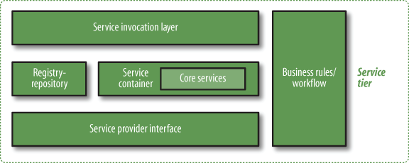
At the core of the service tier (shown in Figure 5-4) is a service container, where service invocation requests are handled and routed to the capabilities that will fulfill the requests, as well as routing the responses or other events, as required. (Java programmers will be familiar with the servlet container model, for example.)
The service container is a component that will assume most of the runtime duties necessary to control a service invocation request and orchestrate the current state, data validation, workflow, security, authentication, and other core functions required to fulfill service requests. In this context, a service container is an instance of a class that can coordinate and orchestrate service invocation requests until the inevitable conclusion, whether successful or not.
Figure 5-4 illustrates several elements within the service tier:
- Service invocation layer
The service invocation layer is where listeners are plugged in to capture events that may trigger services to perform certain actions. It may utilize several types of adapters or event listeners to allow invocation of services; for example, communication endpoints may provide the triggers (typically SOAP or XML over HTTP), or the services may be invoked temporally via timeout events, or even via internal events such as a change in the state of some piece of data within the resource tier. While many articles and papers focus on incoming messages arriving via SOAP endpoints, other forms of invocation are often used.
- Service container
Once a service is invoked, a container instance is spawned to carry out the service invocation request until it is either successfully concluded or hits a fatal error. Service containers may be either short- or long-lived instances, have permissions to access many common and specific services (core services) within the service tier, and can communicate with external capabilities via the service provider interface.
- Business rules and workflow
All service invocation requests are subject to internal workflow constraints and business rules. A service request being fulfilled may have to navigate a certain path in order to reach its final state. Examples include forms being routed to the correct personnel for approval or parameters for a request for data being authenticated to determine if the request meets the business’s acceptance criteria. Some commercial service bus products also offer a workflow engine and designer as part of the service tier.
- Registry/repository
A registry is a central component that keeps track of services, perhaps even in multiple versions. The registry may also track secondary artifacts such as XML schemas, references to service capabilities, and other key resources that are used by the service tier. A repository is a component used to persist resources or data needed during the execution of short- or long-running service invocation requests. The registry and the repository can be used both during design time, to orchestrate amongst multiple services, and at runtime, to handle dynamic computational tasks such as load balancing and resource-instance spawning and to provide a place where governance and monitoring tools can use data to give insight into the state of the entire service tier. Data stored in a repository is often referenced from the registry.
- Service provider interface (SPI)
Since the service tier makes existing capabilities available to be consumed as services, an SPI is required to connect to the resource tier. The resource tier in this case is a generic descriptor for a virtual collection of capabilities. The SPI might be required to communicate with several different types of applications, including CRM systems, databases, ECM systems, plain old Java objects (POJOs), or any other resources that provide the capabilities to power a service.
Service containers are the physical manifestation of abstract services and provide the implementation of the internal service interfaces. This can require substantial coordination. If, for example, a service request proves to be outside the service policy constraints, the service container might be required to generate a fault and possibly roll back several systems to account for the failed invocation request, as well as notifying the service invoker. The service container depicted in Figure 5-4 might also use the registry/repository to help in service fulfillment.
Additionally, the core service tier ties into backend capabilities via the SPI. Implementers of Web 2.0–type applications will have to consider the following integration questions while designing their systems, some of which will affect how the SPI is configured and what protocols it must handle:
What systems or capabilities will I want to connect with?
What set of core services will I need to provide as part of my infrastructure? (Some examples include authentication, encryption, and email notifications.)
What business rules will I have to enforce during the service invocation process, and how will I describe and monitor them?
How will services be invoked? What invocation patterns will transpire within my infrastructure?
There are other complications as well. Service interaction patterns may vary from a simple stateless request/response pair to a longer-running subscribe/push. Other service patterns may involve interpretation of conditional or contextual requests. Many different patterns can be used to traverse the service tier, and the semantics associated with those patterns often reside with the consumer’s particular “view.” For example, if a person is requesting a service invocation to retrieve data, he may define that service pattern as a data service. From a purely architectural perspective, however, this is not the case, because every service has a data component to it (for more specifics on the relationship between a service and data, see the discussion of the SOA pattern in Chapter 7). Another person with a more specific view might try to define the service as a financial data service. This is neither right nor wrong for the consumer, as it likely helps her to understand the real-world effects of the service invocation. However, the granularity and purpose of the service pattern is in the eye of the beholder.
Service oregistries are central to most SOAs. At runtime they act as points of reference to correlate service requests to concrete actions, in much the same way the Windows operating system registry correlates events to actions. A service registry has metadata entries for all artifacts within the SOA that are used at both runtime and design time. Items inside a service registry may include service description artifacts (WSDL), service policy descriptions, XML schemas used by various services, artifacts representing different versions of services, governance and security artifacts (certificates, audit trails), and much more. During the design phase, business process designers may use the registry to link together calls to several services to create a workflow or business process.
Service registries help enterprises answer the following questions:
How many processes and workflows does my IT system fulfill?
Which services are used in those processes and workflows?
What XML schemas or other metadata constraints are used for the services within my enterprise?
Who is using the services I have within my enterprise?
Do I have multiple services doing the same function?
What access control policies do I have on my services?
Where can users of my services be authenticated?
What policies do I have that are common to multiple services?
What backend systems do my services talk to in order to fulfill invocation requests?
This is only a starter set of questions; you may come up with many more. The SOA registry/repository is a powerhouse mechanism to help you address such questions.
It’s also worth discussing the service invocation layer in Figure 5-4 in greater detail. The service invocation layer is where service invocation requests are passed to the core service container. The service invocation layer can hook into messaging endpoints (SOAP nodes, Representational State Transfer interfaces, HTTP sockets, JMS queues, and so on), but service invocations may also be based on events such as a timeouts, system failures and subsequent powerups, or other events that can be trapped. Client software development kits (SDKs), customer libraries, or other human or application actor interactions can also initiate invocation requests. In short, remember that several potential types of invocations are inherent in SOA design and to fulfill the patterns of Web 2.0 flexibility should be maintained by using the service invocation layer as a sort of “bus” to kick off service invocations. Realizing that patterns other than request/response via SOAP (what many people consider to be SOA) may be employed to invoke services will result in a much more flexible architecture.
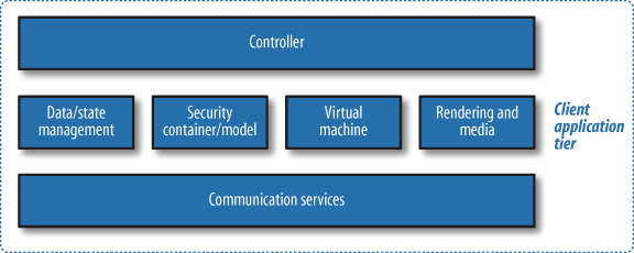
The client application tier of the Web 2.0 Reference Architecture, shown in Figure 5-5, contains several functional components that are managed by the controller, the core application master logic and processing component. Every client application has some form of top-level control. The concept used here is in alignment with the controller concept in the Model-View-Controller (MVC) pattern.
Web 2.0 clients often have several runtime environments. Each runtime is contained and facilitated by a virtual machine. Thus, while the runtime environments are launched and managed by a single controller, they remain somewhat autonomous with respect to executing scripts or bytecode to control certain aspects of an application. The virtual machine itself is a specialized type of controller, but it’s controlled by a master controller that’s responsible for launching and monitoring virtual machines and runtime environments as they’re required.
To clarify the relationships, let’s break out each component in the client application tier diagram, starting at the top:
- Controller
The controller contains the master logic that runs all aspects of the client tier. If the client is a browser, for example, the core browser logic is responsible for making a number of decisions with respect to security and enforcement, launching virtual machines (such as Flash Player or the Java Virtual Machine), rendering tasks pertaining to media, managing communication services, and managing the state of any data or variables.
- Data/state management
Any data used or mutated by the client tier may need to be held in multiple states to allow rollback to a previous state or for other auditing purposes. The state of any applications running on the client tier may also need to be managed. Companies like Google and Adobe are getting very aggressive in developing advanced functionality with respect to data and state management to allow online and offline experiences to blend (i.e., using Google Gears and the Adobe Integrated Runtime, or AIR). Mozilla’s Firefox browser now supports connections to SQLite databases as well.
- Security container/model
A security model expresses how components are constrained to prevent malicious code from performing harmful actions on the client tier. The security container is the physical manifestation of the model that prevents the runtime enactment of those malicious scenarios. Almost every client-tier application includes some kind of security model (unrestricted access to local resources is in fact a security model), and each must have a corresponding set of mechanisms to enforce its security policies. A security sandbox in a browser, for example, prevents website authors from injecting into a web page any code that might execute in a malicious manner on the user’s machine.
- Virtual machines
Virtual machines (VMs) are plug-ins that can emulate a specific runtime environment for various client-side technologies. Virtual machines were the foundation for Java, including its early move to the Web as “applets,” but the busiest VM these days is likely the ActionScript Virtual Machine, the core runtime behind Adobe’s Flash. VMs are often built in alignment with the applications’ security models to constrain runtime behavior from leaving the emulated environment.
- Rendering and media
Management of the media and rendering processes is required to present a graphical interface to users (assuming they are humans). The client tier handles all aspects of rendering. For example, in a browser, HTML and CSS might first be parsed and an internal representation made in memory, which can be subsequently used to build a “view” of the web page.
- Communications
With every client-tier application, communication services are required. These are often constrained in accordance with the security model and orchestrated by the controller based on a number of criteria (online/offline synchronization, small AJAX-like calls back to the server, etc.). The communications aspect of the client tier usually incorporates various stacks and protocols so that it can speak HTTP and HTTPS, supports the
XMLHTTPRequestobject, and more.
The client-side rendering engine handles all the “view” behavior for GUIs, as well as media integration. Rendering engines also pass information to the virtual machines and are controlled by the master controller. The data/state management mechanisms in the client tier control transformations, state synchronizations, transitions, and state change event generation during the object life cycle.
On client systems, allowing access to local resources—even read-only privileges—represents a primary security risk. A sandbox philosophy typically confines the runtime environment and keeps it separate from the local system. Access to local system resources is usually denied unless explicitly granted for browser-based applications, unlike desktop applications, which enjoy a greater deal of interaction. There’s also a new breed of hybrid smart client applications that exist outside the browser, without being full-featured applications. Examples include widgets, gadgets, and Adobe’s AIR applications. These applications use a hybrid security model that must be carefully thought out, as smart client and composite applications that mash up content from more than one site can experience runtime problems with mismatched security privileges between domains.
The communication services manage all communications, including between the client and server, with the host environment, and with resources in other tiers. Together with data/state management services, the communication services must be aware of the connection status and understand when to locally cache data and where to go to synchronize data states once interrupted connections are reestablished. Several of the patterns discussed in Chapter 7, such as the Synchronized Web and Mashup patterns, require a careful orchestration of these resources.