
Chapter 14. Sensors
In This Chapter
• Accelerometer sensor
• Smoothing sensor readings
• Compass sensor
• Gyroscope sensor
• Motion sensor
• Sensor calibration
Chapter 11, “Touch,” looked at touch input and gestures, which is ordinarily the first choice for user input in most Windows Phone apps. Yet the hardware of Windows Phone devices provides additional sensors that can be used for input, including an accelerometer, compass, and gyroscope, along with a combined virtual sensor called the motion sensor.
This chapter examines each sensor in detail, beginning with the accelerometer. You see how to process accelerometer readings, and how to simulate acceleration within the Windows Phone emulator. You learn how to apply data smoothing to accelerometer readings to decrease jittering of UI elements without sacrificing responsiveness. You also see how to calibrate the accelerometer, and how to perform shake detection using the accelerometer.
The chapter then looks at the compass sensor and how to use the compass’s magnetic heading to build a custom compass app that displays the heading using an arrow. How compass calibration is performed is also discussed.
The chapter then moves to the gyroscope sensor, and you see how to build a UI to display the angular rotation of the phone.
Finally, the chapter discusses the motion sensor, which is a virtual sensor that harnesses the other hardware sensors to improve accuracy and provide extended orientation and motion information.
Sensors Overview
All sensor classes derive from the class SensorBase<TSensorReading>, allowing you to work with what will become a familiar programming model. SensorBase ensures that sensors and readings are treated in the same way, a consistency that you will come to appreciate the more you work with sensors. The only variation occurs in the type of data that each sensor provides as a reading.
SensorBase<TSensorReading> has the following three properties:
• CurrentValue
• IsDataValid
• TimeBetweenUpdates
Windows Phone sensors use an event-based model for monitoring changes to sensor readings. When new data arrives from the sensor, the SensorBase<TSensorReading>.CurrentValueChanged event is raised, providing the ability to periodically process sensor readings. The type of reading depends on the type of sensor you are using. For example, the accelerometer uses an AccelerometerReading.
The CurrentValueChanged event is not raised on the UI thread. It is therefore important to invoke any updates to the UI using a Dispatcher. This, however, poses no challenge if you choose to use the property change notification infrastructure present in the downloadable sample code.
The interval between sensor readings can be set using the TimeBetweenUpdates property, which is of type TimeSpan. By default, this value is 17, 20, or 25 milliseconds, depending on the type of sensor. Setting the TimeBetweenUpdates to a value not supported by the sensor silently fails.
If you require a specific value for the TimeBetweenUpdates interval, be sure to test the value of the property after it is set to ensure that the value was actually assigned.
The CurrentValue property holds the value of the most recent sensor reading taken. A good habit to get into is to make sure you check the IsDataValid property, which indicates whether the sensor’s CurrentValue property contains valid data before retrieving the value from the CurrentValue property.
Two methods, Start and Stop, are used to start and stop acquisition of data from the sensor. Sensors consume native resources on the device and may unduly impact battery consumption if they are kept alive for longer than they are needed. It is therefore important to call Start only when sensor readings are needed, and to call Stop as soon as the new sensor readings are no longer needed.
SensorBase<TSensorReading> implements IDisposable. Calling Dispose on a sensor releases the managed and unmanaged resources used by the sensor. Obviously it is wise to dispose of sensors once they are not needed, such as when your app is deactivated; however, SensorBase<T> automatically subscribes to the PhoneApplicationService.Closing event, and when the event is raised, calls its own Dispose method. This means that, no matter what happens, resources related to the native sensor are correctly released when your app exits.
The accelerometer, compass, motion, and gyroscope are limited to 10 instances of each type. If this number is exceeded, a SensorFailedException is raised when the sensor class’s Start method is called. If this occurs, you can notify the user, providing this reason as a potential cause, and instruct him to uninstall another app that uses the same sensor type.
The sensor classes available in the Windows Phone 7.1 SDK reside in the Microsoft.Devices.Sensors namespace, and include the Accelerometer, Compass, Gyroscope, and Motion classes. To use any of the sensors add a reference to the Microsoft.Devices.Sensors assembly.
The following sections look at each sensor, beginning with the accelerometer.
Measuring Force with the Accelerometer
The accelerometer sensor measures the force applied to the device. The sensor detects the force of gravity along with any forces resulting from the movement of the phone. When the device is stationary, this force is equal to that of earth’s gravity. Thus, when stationary, the accelerometer provides the position of the phone relative to the earth. When in the hands of a user, the accelerometer can be used to determine in which direction the user is moving the device, and when the phone is moved suddenly, while playing a game for example, the force may exceed that of gravity.
The accelerometer is normally used for determining whether the phone is tilted. But it can also be used to allow the device to become the controller, such as steering a car in a game.
The accelerometer measures force in gravitational units (g’s), where 1 g equals (by definition) 9.80665 m/s2 (32.1740 ft/s2).
Ideally, when stationary, accelerator readings range from -1 to 1. Slight variations introduced by differences in the earth’s gravity around the world may take the value outside this range.1
1 Gravity ranges at it is lowest in Mexico City (9.779 m/s2) and highest in Oslo (Norway) and Helsinki (Finland) (9.819 m/s2). Source: http://en.wikipedia.org/wiki/Gravity_of_Earth
Theoretically, if you dropped your phone, in free fall the phone’s accelerometer should read 0.
The accelerometer measures force in three directions. The acceleration value is represented as a three-dimensional vector, representing the dimension components X, Y, and Z axes (see Figure 14.1). The three-dimensional vector represents the direction from the point (0, 0, 0). For example, when the device is placed on a level surface with its screen facing upward, the Z-axis registers a value of -1 g. You can get a feel for the acceleration effects of tilting and flipping the phone using the sample page for this chapter, discussed in a moment.

Figure 14.1. Effects on axis values when facing upward
Using the Accelerometer Class
Accelerometer, like the other sensor types, uses an event-based model for monitoring changes to sensor readings.
Accelerometer contains a ReadingChanged event, which should not be used as it is a remnant of the first release of the Windows Phone OS and has been deprecated in the 7.1 release of the SDK.
The event to use is the base class SensorBase event: CurrentValueChanged. Subscribing to the event can be done as follows:
var accelerometer = new Accelerometer();
accelerometer.CurrentValueChanged += HandleSensorValueChanged;
accelerometer.Start();
When the CurrentValueChanged event is raised, the event handler receives a SensorReadingEventArgs<AccelerometerReading> object, as shown:
void HandleSensorValueChanged(
object sender, SensorReadingEventArgs<AccelerometerReading> e)
{
ProcessReading(e.SensorReading);
}
SensorReadingEventArgs provides a reference to the Accelerometer via its single Sensor property. AccelerometerReading contains an Acceleration property, which is a Microsoft.Xna.Framework.Vector3. Silverlight does not have a type representing a three-dimensional vector baked into the SDK, thus there is some crossover here, and Vector3 is used throughout the phone sensor API.
Rather than relying on the XNA Vector3 type in the sample code, a custom ThreeDimensionalVector class is used that has a markedly simpler implementation and uses properties rather than fields to access vector dimension values, which improves its compatibility with the Silverlight data binding infrastructure.
Simulating Acceleration with the Emulator
At times it may be difficult to test an app directly on a real device, such as when you are developing an app for a new version of the Windows Phone SDK that has not yet been rolled out to phone devices. Fortunately, the emulator has a tool for simulating the accelerometer, which can be accessed by clicking on the Additional Tools button of the emulator menu (see Figure 14.2).

Figure 14.2. Click the bottom arrow on the emulator menu to launch the Additional Tools window.
The Accelerometer tab of the Additional Tools window allows you to manipulate the position of the virtual device; moving the small red circle affects the reading taken by the Accelerometer class (see Figure 14.3).

Figure 14.3. The emulator’s accelerometer simulator
Within the emulator, the accelerometer is not subject to environmental effects, and readings taken within the emulator are perfectly stable.
While the emulator provides the means to test code that relies on the accelerometer, it is important to test your code on an actual device, to see how it behaves in real-world conditions.
Smoothing Accelerometer Readings
The Accelerometer’s CurrentValueChanged event is raised, by default, 50 times a second and reflects the raw hardware sensor readings. Updating UI elements based on the raw values from the accelerometer can make elements appear jittery, much like the effects of Brownian motion under a microscope. You can allow your app to appear more stable by smoothing the readings received by the accelerometer through ignoring small changes in acceleration.
Some apps may benefit from some degree of smoothing, yet may need to react quickly to sudden fluctuations in reading values, such as games, which usually need input to be as direct as possible. This section looks at applying various data smoothing techniques to reduce jitter while also minimizing latency.
Much of the code and theory in this section is based on an article on the Windows Team Blog by Dave Edson http://bit.ly/cXJ2EC. It is recommended that you take a look at the article to better understand the theory behind the smoothing algorithms employed in the sample code. The advantage of the sample code provided here is that you also have a number of other features included that you can take and use immediately in your own apps.
The example code for this section is located in the Devices/Sensors directory of the WindowsPhone7Unleashed project in the downloadable sample code.
In the example, a custom class called EnhancedAccelerometer is used in place of the built-in Accelerometer. The EnhancedAccelerometer class uses an Accelerometer, allowing the application of smoothing algorithms based on previous readings. EnhancedAccelerometer has a number of features that the Accelerometer does not, such as calibration support, shake detection, and of course data smoothing.
Like the Accelerometer, the EnhancedAccelerometer is IDisposable. When the EnhancedAccelerometer is disposed, it in turn disposes the built-in Accelerometer. So too, EnhancedAccelerometer is started by calling its Start method, which instantiates an Accelerometer, subscribes to its CurrentValueChanged event, and starts the Accelerometer as shown:
public void Start()
{
if (accelerometer == null)
{
lock (accelerometerLock)
{
if (accelerometer == null)
{
accelerometer = new Accelerometer();
accelerometer.CurrentValueChanged
+= HandleSensorValueChanged;
accelerometer.Start();
}
}
}
}
EnhancedAccelerometer has a Reading property of type EnhancedAccelerometerReading, which not only supplies the raw value supplied by the Accelerometer, but also the following three smoothed reading values:
• AverageAcceleration
• LowPassFilteredAcceleration
• OptimallyFilteredAcceleration
Each value is the result of the application of a particular smoothing algorithm. The first, AverageAcceleration, has the highest latency (lag) of the three, while the other two attempt to combat the latency by responding to large reading variations immediately so that you get smoothing as well as responsiveness. These properties are examined in greater detail in the following sections.
AverageAcceleration
The AverageAcceleration property provides an average value of the last 25 readings. As stated, this approach has the highest latency; a large change in acceleration is less evident as the previous readings average it out. This approach may suit an app that requires input to be very steady—a spirit level app for example—but would not be suitable for a game that needs to respond quickly to user input.
LowPassFilteredAcceleration
The LowPassFilteredAcceleration property is calculated using the current reading and the previously calculated output. This approach has less latency than averaging, yet still does not respond to large changes in acceleration immediately.
The EnhancedAccelerometer.LowPassFilterCoefficient property allows you to adjust the level of smoothing applied to the output value. Each reading dimension value is calculated like so:
double newOutputValue = priorOutputValue
+ LowPassFilterCoefficient * (newInputValue - priorOutputValue);
By decreasing the LowPassFilterCoefficient, more smoothing is applied.
OptimallyFilteredAcceleration
The OptimallyFilteredAcceleration property uses a low pass filter in conjunction with a threshold value, which causes the output value to be set to the raw reading immediately if the reading exceeds the threshold value. This approach eliminates the latency of the pure low pass approach for sharp changes in acceleration.
If the difference between a new reading and the previous output is greater than the noise threshold, then the raw value is used, as shown in the following excerpt:
double ApplyLowPassFilterWithNoiseThreshold(
double newInput, double previousOutput)
{
double newOutputValue = newInput;
if (Math.Abs(newInput - previousOutput) <= NoiseThreshold)
{
/* A simple low-pass filter. */
newOutputValue = previousOutput
+ LowPassFilterCoefficient * (newInput - previousOutput);
}
return newOutputValue;
}
The noise threshold of the filter can be adjusted using the EnhancedAccelerometer.NoiseThreshold property. Its default value is 0.05, and by increasing the value you increase the level of acceleration needed to produce an immediate response.
Calibrating the Accelerometer
The built-in Accelerometer does not provide calibration support out of the box. Moreover, there is no systemwide calibration setting that your app can update. It is up to your app to have the user place the phone in a level position, calculate an offset value, and save the offset value in isolated storage.
The custom EnhancedAccelerometer provides support for calibrating a device placed on a level surface. It includes the following two calibration related methods:
• bool CanCalibrate()
• bool Calibrate()
CanCalibrate determines whether the device is stable enough for calibration to take place and is determined by measuring the variation of the last several readings and whether the current X, Y, and Z axes do not stray too far from the ideal level position. The level of allowed variation can be specified using the MaximumStabilityTiltDeltaAngle property, which is set to half a degree (0.5 * Math.PI / 180.0) by default.
The ideal level vector is (0,0,-1). The allowed variation from the ideal vector can be specified using the EnhancedAccelerometer’s MaximumCalibrationTiltAngle property, which is set to 20 degrees (20.0 * Math.PI / 180.0) by default.
Sample Accelerometer View
The sample for this section is located in the Sensors/Accelerometer directory of the WindowsPhone7Unleashed.Examples project in the downloadable sample code. It uses the EnhancedAccelerometer via a custom IAccelerometer interface. This enables a mock accelerometer to be supplanted for testing purposes.
The AccelerometerView page presents four sliders for viewing the various readings from the EnhancedAccelerometer. Its viewmodel, the AccelerometerViewModel class, contains the following three commands:
• StartCommand
• StopCommand
• CalibrateCommand
StartCommand subscribes to the IAccelerometer.ReadingChanged event and calls the IAccelerometer’s Start method, while StopCommand unsubscribes from the event and calls IAccelerometer’s Stop method (see Listing 14.1).
CalibrateCommand uses the IAccelerometer.CanCalibrate method to determine whether the command can execute, which in turn sets the enabled state of the view’s AppBar button.
Listing 14.1. AccelerometerViewModel Constructor
public AccelerometerViewModel(IAccelerometer accelerometer) : base("accelerometer")
{
startCommand = new DelegateCommand(
obj =>
{
accelerometer.ReadingChanged -= HandleReadingChanged;
accelerometer.ReadingChanged += HandleReadingChanged;
accelerometer.Start();
});
stopCommand = new DelegateCommand(
obj =>
{
accelerometer.ReadingChanged -= HandleReadingChanged;
accelerometer.Stop();
});
calibrateCommand = new DelegateCommand(
obj => MessageService.ShowMessage(accelerometer.Calibrate()
? "Successfully calibrated."
: "Unable to calibrate."),
obj => accelerometer.CanCalibrate());
}
When a new reading is received, the viewmodel’s HandleReadingChanged handler sets the viewmodel’s Reading property to the IAccelerometer’s EnhancedAccelerometerReading, as shown:
void HandleReadingChanged(object sender, EventArgs e)
{
IAccelerometer accelerometer = (IAccelerometer)sender;
Reading = accelerometer.Reading;
UpdateCommands();
}
The UpdateCommands method calls calibrateCommand.RaiseCanExecuteChanged(), which updates the enabled state of an AppBar button.
The view executes the viewmodel’s Start command within the OnNavigatedTo method and the Stop command in the OnNavigatedFrom method, thus ensuring that the native Accelerometer is disposed when another page is shown or the app is deactivated (see Listing 14.2).
Listing 14.2. AccelerometerView Class
public partial class AccelerometerView : PhoneApplicationPage
{
public AccelerometerView()
{
InitializeComponent();
DataContext = new AccelerometerViewModel(
new EnhancedAccelerometer(new IsolatedStorageUtility()));
}
AccelerometerViewModel ViewModel
{
get
{
return (AccelerometerViewModel)DataContext;
}
}
protected override void OnNavigatedTo(NavigationEventArgs e)
{
base.OnNavigatedTo(e);
ViewModel.StartCommand.Execute(null);
}
protected override void OnNavigatedFrom(NavigationEventArgs e)
{
base.OnNavigatedFrom(e);
ViewModel.StopCommand.Execute(null);
}
}
The view’s XAML contains a custom AppBar with an AppBarIconButton that is bound to the viewmodel’s CalibrateCommand, as shown:
<u:AppBar>
<u:AppBarIconButton
Command="{Binding CalibrateCommand}"
Text="Calibrate"
IconUri="/Sensors/Accelerometer/Icons/AppbarCalibrate.png" />
</u:AppBar>
The view’s main content panel contains several grids, each displaying a value from the EnhancedAccelerometerReading:
<Grid>
<TextBlock Text="raw"
Style="{StaticResource PhoneTextGroupHeaderStyle}" />
<Slider Value="{Binding Reading.RawAcceleration.X,
Converter={StaticResource SquashConverter}}"
Style="{StaticResource SliderStyle}" Margin="0" />
<Slider Value="{Binding Reading.RawAcceleration.Y,
Converter={StaticResource SquashConverter}}"
Style="{StaticResource SliderStyle}" Margin="0,30,0,0" />
<Slider Value="{Binding Reading.RawAcceleration.Z,
Converter={StaticResource SquashConverter}}"
Style="{StaticResource SliderStyle}" Margin="0,60,0,0" />
<TextBlock Text="{Binding Reading.RawAcceleration}"
Margin="16,90,0,0" />
</Grid>
The SquashConverter is a custom IValueConverter that ensures the Slider always has a positive value that is within the range of 0 and 2, thus preventing binding failures.
The AccelerometerView page allows you to get a feel for the behavior of the accelerometer and to experiment with the various smoothing functions provided by the custom EnhancedAccelerometer (see Figure 14.4).
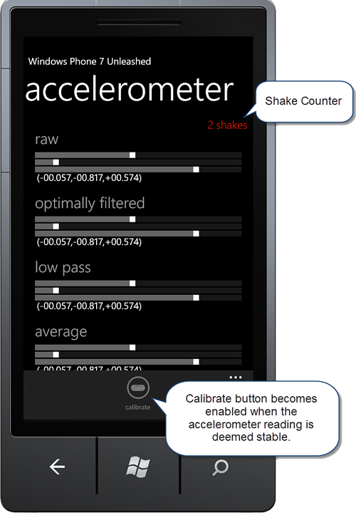
Figure 14.4. AccelerometerView page
By placing your phone device face up on a flat surface, the calibrate button becomes enabled.
Shake Detection
The phone SDK does not come with any built-in support for detecting when the device is being shaken. This section extends the custom EnhancedAccelerometer to provide shake detection.
The EnhancedAccelerometer.IsShake method returns true if the difference between the current and previous acceleration readings exceeds a threshold value for two or more dimensional components, in which case, the movement is deemed a shake. Thanks to Mark Monster, http://bit.ly/9GMDJX, on which this code is based. See the following excerpt:
static bool IsShake(Vector3 currentAcceleration,
Vector3 previousAcceleration, double threshold)
{
double deltaX = Math.Abs(previousAcceleration.X - currentAcceleration.X);
double deltaY = Math.Abs(previousAcceleration.Y - currentAcceleration.Y);
double deltaZ = Math.Abs(previousAcceleration.Z - currentAcceleration.Z);
return deltaX > threshold && deltaY > threshold
|| deltaX > threshold && deltaZ > threshold
|| deltaY > threshold && deltaZ > threshold;
}
A Shake event has been added to the IAccelerometer interface. When a new reading is received from the Accelerometer within the EnhancedAccelerometer, the DetectShake method is called (see Listing 14.3). If a shake is detected, then the Shake event is raised.
Two threshold properties control sensitivity during shake detection. Both threshold properties are of type double, representing the threshold in radians. The first, ShakeThreshold, is used to determine when a shake has begun; the second, ShakeEndThreshold, defines the maximum value of the acceleration delta, used for detecting when the device is no longer being shaken.
Listing 14.3. EnhancedAccelerometer.DetectShake Method
void DetectShake(Vector3 acceleration)
{
EventHandler tempEvent = Shake;
if (tempEvent == null || !previousAcceleration.HasValue)
{
return;
}
Vector3 previousValue = previousAcceleration.Value;
bool shakeDetected = IsShake(acceleration, previousValue, shakeThreshold);
if (shakeDetected && !shaking && shakeCount > 0)
{
shaking = true;
shakeCount = 0;
OnShake(EventArgs.Empty);
}
else if (shakeDetected)
{
shakeCount++;
}
else if (!IsShake(acceleration, previousValue, shakeEndThreshold))
{
shakeCount = 0;
shaking = false;
}
}
The AccelerometerViewModel subscribes to the IAccelerometer.Shake event. When the event is raised, the viewmodel’s ShakeCount property is incremented. ShakeCount is displayed using a TextBlock, as shown:
<TextBlock Text="{Binding ShakeCount, StringFormat='{0} shakes'}"
Style="{StaticResource LabelTextStyle}"
Foreground="{StaticResource PhoneAccentBrush}"
HorizontalAlignment="Right" />
All Windows Phone devices are required to have an accelerometer, and the accelerometer API has been present since the first release of the phone SDK. It is, therefore, a staple piece of Windows Phone tech that offers a reliable way of enriching your app with movement sensing.
Measuring Direction with the Compass
The compass, also known as the magnetometer, is a Windows Phone required sensor that allows your app to determine which direction the phone is pointing, in particular, the offset from magnetic or geographic north.
The compass is useful in applications that use geographic location; for example, you may want to provide a compass arrow as a supplement for a mapping app. The compass also allows you to monitor raw magnetometer readings and to detect changes to magnetic forces around the device.
The sample code for this section creates a page that displays a compass arrow and the various compass readings, and you see how to allow the user to calibrate the compass.
The sample code for this section resides in the /Sensors/Compass/ directory of the WindowsPhone7Unleashed.Examples project in the downloadable sample code.
The compass sensor is rather subject to interference. Bringing the device into close proximity of large metallic objects or other electronic devices, for example, a laptop, throws off the reading.
Using the Compass Sensor
The compass sensor is a required component of Windows Phone devices. In the first release of the Windows Phone OS (7.0), however, no API was provided for the compass, and some devices lacked the native drivers necessary to use the compass even when running the Windows Phone 7.5 OS (mango). If you are maintaining an app for a pre-mango device it is therefore important to verify that the compass is supported before attempting to use it. For this, the static Compass.IsSupported property is used, as demonstrated in the CompassViewModel class (see Listing 14.4). The Start method of the CompassViewModel oversees the creation of the Compass instance.
The default value of the compass TimeBetweenUpdates property is 25 milliseconds, which on my test device was the minimum allowed value.
As with all sensor types, the CurrentValueChanged event is used to receive periodic updates from the sensor.
The Calibrate event allows your app to respond to when the phone is calibrating the sensor. Calibration is discussed further later in this section.
Calibration is an activity triggered by the OS; there is no PerformCalibration method that you can call to cause the device to begin calibration.
Listing 14.4. CompassViewModel.Start Method (excerpt 1)
public void Start()
{
if (!Compass.IsSupported)
{
MessageService.ShowMessage("Compass is not supported on this device.");
return;
}
compass = new Compass();
compass.TimeBetweenUpdates = TimeSpan.FromMilliseconds(updateIntervalMs);
UpdateIntervalMs = (int)compass.TimeBetweenUpdates.TotalMilliseconds;
compass.CurrentValueChanged += HandleCompassCurrentValueChanged;
compass.Calibrate += HandleCompassCalibrate;
compass.Start();
...
}
When the CurrentValueChanged event is raised, the event handler receives a SensorReadingEventArgs<CompassReading> object. CompassReading contains the five properties listed in Table 14.1.
Table 14.1. CompassReading Properties

The handler for the Compass object’s CurrentValueChanged event in the CompassViewModel extracts the values from the event arguments and assigns them to various viewmodel properties of the same name. XNA’s Vector3 data type is not amenable to data binding because it exposes its X, Y, and Z dimensions as public fields. Rather than use Vector3, a custom ThreeDimensionalVector object is created using the Vector3 values, as shown in the following excerpt:
void HandleCompassCurrentValueChanged(
object sender, SensorReadingEventArgs<CompassReading> e)
{
MagneticHeading = e.SensorReading.MagneticHeading;
TrueHeading = e.SensorReading.TrueHeading;
HeadingAccuracy = e.SensorReading.HeadingAccuracy;
Vector3 reading = e.SensorReading.MagnetometerReading;
MagnetometerReading = new ThreeDimensionalVector(reading.X,
reading.Y,
reading.Z);
SmoothedReading
= readingSmoother.ProcessReading(e.SensorReading.MagneticHeading);
}
The raw sensor readings for MagneticHeading and TrueHeading are subject to slight variations in magnetic forces and, like the accelerometer, can make elements look unsteady when bound directly to the UI. A custom class, called ReadingSmoother, is used to dampen the stream of sensor reading values. I have abstracted the data smoothing code of the EnhancedAccelerometer, which was presented in the “Smoothing Accelerometer Readings” section of this chapter, into a new class called ReadingSmoother. The ReadingSmoother class uses the strategy pattern to allow you to change its filtering behavior via an IFilterStrategy interface provided to its constructor, as shown:
public ReadingSmoother(
IFilterStrategy filterStrategy = null, int samplesCount = 25)
{
...
}
Listing 14.5 shows the ReadingSmoother.ProcessReading method. ReadingSmoother tracks the previous 25 values provided to it and uses the IFilterStrategy to smooth the data.
Listing 14.5. ReadingSmoother.ProcessReading Method
public double ProcessReading(double rawValue)
{
double result = rawValue;
if (!initialized)
{
lock (initilizedLock)
{
if (!initialized)
{
/* Initialize buffer with first value. */
sampleSum = rawValue * samplesCount;
averageValue = rawValue;
for (int i = 0; i < samplesCount; i++)
{
sampleBuffer[i] = averageValue;
}
initialized = true;
}
}
}
double latestValue;
if (filterStrategy != null)
{
latestValue = result = filterStrategy.ApplyFilter(rawValue, result);
}
else
{
latestValue = rawValue;
}
/* Increment circular buffer insertion index. */
if (++sampleIndex >= samplesCount)
{
/* If at max length then wrap samples back
* to the beginning position in the list. */
sampleIndex = 0;
}
/* Add new and remove old at sampleIndex. */
sampleSum += latestValue;
sampleSum -= sampleBuffer[sampleIndex];
sampleBuffer[sampleIndex] = latestValue;
averageValue = sampleSum / samplesCount;
/* Stability check */
double deltaAcceleration = averageValue - latestValue;
if (Math.Abs(deltaAcceleration) > StabilityDelta)
{
/* Unstable */
deviceStableCount = 0;
}
else
{
if (deviceStableCount < samplesCount)
{
++deviceStableCount;
}
}
if (filterStrategy == null)
{
result = averageValue;
}
return result;
}
The ReadingSmoother instance is defined as a field of the viewmodel, like so:
readonly ReadingSmoother readingSmoother
= new ReadingSmoother(new LowPassFilterStrategy());
LowPassFilterStrategy removes noise from the raw sensor values, while allowing fast changes of sufficient amplitude to be detected. See the LowPassFilterStrategy source in the downloadable sample code for more detail.
The content panel of the CompassView page displays the various viewmodel properties, including the current magnetic heading and the accuracy of the compass. In addition, the viewmodel’s SmoothedReading is displayed using an arrow. The arrow is defined as a Silverlight Path. An enclosing Canvas uses a RotateTransform, which is bound to the SmoothedReading property, to rotate to the compass heading value. See the following excerpt:
<Canvas Width="280" Height="100">
<Path Width="275" Height="95"
Canvas.Left="0" Canvas.Top="0" Stretch="Fill"
Fill="{StaticResource PhoneAccentBrush}"
Data="** Arrow points omitted **">
<Path.RenderTransform>
<RotateTransform Angle="-90"
CenterX="140" CenterY="48" />
</Path.RenderTransform>
</Path>
<Canvas.RenderTransform>
<RotateTransform Angle="{Binding SmoothedReading,
Converter={StaticResource NegateConverter}}"
CenterX="140" CenterY="48" />
</Canvas.RenderTransform>
</Canvas>
A custom IValueConverter, called NegateConverter, is used to negate the value so that the arrow’s heading corresponds to north, rather than the offset value. The NegateConverter.Convert method is shown in the following excerpt:
public object Convert(
object value, Type targetType, object parameter, CultureInfo culture)
{
double degrees = (double)value;
return -degrees;
}
Figure 14.5 shows the CompassView page with the heading arrow pointing to magnetic north. As the phone is rotated, the arrow maintains its heading.

Figure 14.5. CompassView page with arrow pointing to magnetic north
The compass orientation value, shown in Figure 14.5, is determined by the accelerometer. This value is discussed in the following section.
Compass Orientation
The compass API uses a single axis to calculate the heading, depending on the orientation of the device. The device may be flat with its screen facing up, or it may be in an upright portrait position.
The Compass class does not provide the means to determine which orientation it is using; rather, you use an Accelerometer to tell you.
The viewmodel’s Start method also includes the initialization of an Accelerometer (see Listing 14.6).
Listing 14.6. CompassViewModel.Start Method (excerpt 2)
public void Start()
{
...
accelerometer = new Accelerometer();
accelerometer.CurrentValueChanged += HandleAccelerometerCurrentValueChanged;
accelerometer.Start();
}
The orientation of the compass is represented using a custom enum called CompassOrientation. It has two values: Flat and Portrait. Listing 14.7 shows how the Accelerometer’s CurrentValueChanged event handler calculates the orientation of the device using the Y and Z dimensional components of the reading vector.
Listing 14.7. HandleAccelerometerCurrentValueChanged Method
void HandleAccelerometerCurrentValueChanged(
object sender, SensorReadingEventArgs<AccelerometerReading> e)
{
Vector3 accelerationVector = e.SensorReading.Acceleration;
bool usingNegativeZAxis = false;
/* Determine the orientation of the device. */
if (Math.Abs(accelerationVector.Z) < Math.Cos(Math.PI / 4)
&& accelerationVector.Y < Math.Sin(7 * Math.PI / 4))
{
usingNegativeZAxis = true;
}
CompassOrientation = usingNegativeZAxis
? CompassOrientation.Portrait
: CompassOrientation.Flat;
}
Calibrating the Compass
Over time, the compass sensor can become inaccurate, and this is exacerbated if it is exposed to magnetic fields. Calibration of the device is performed by the user, by moving the phone repeatedly in a figure eight pattern (see Figure 14.6). The Compass.Calibrate event is raised whenever the OS detects that the heading accuracy is worse than 20 degrees, at which point it is your app’s responsibility to display a dialog to the user with instructions on how to perform the calibration motion.
The CompassView page includes a StackPanel with the calibration UI, consisting of an image with instructions for performing the figure eight motion (see Listing 14.8).
As the user performs the calibration motion, the accuracy level is displayed in a TextBlock that is bound to the viewmodel’s HeadingAccuracy property. Once the user is satisfied that she has improved the accuracy of the sensor sufficiently, she taps a done button. The button is bound to the viewmodel’s ToggleCalibrationCommand.
Listing 14.8. Calibration UI XAML (excerpt from CompassView.xaml)
<StackPanel x:Name="stackPanel_Calibration" Visibility="Collapsed"
Background="{StaticResource PhoneBackgroundBrush}">
<Image Source="/Sensors/Compass/Images/CalibrateCompass.png"
HorizontalAlignment="Center"/>
<TextBlock TextWrapping="Wrap" TextAlignment="Center">
The compass on your device needs to be calibrated.
Hold the device in front of you and sweep it through
a figure eight pattern as shown, until the calibration is complete.
</TextBlock>
<StackPanel Orientation="Horizontal" Margin="0,10"
HorizontalAlignment="Center">
<TextBlock Text="accuracy is "
Style="{StaticResource LabelTextStyle}" />
<TextBlock Text="{Binding HeadingAccuracy, StringFormat={0}°}"
Style="{StaticResource PhoneTextAccentStyle}"
FontSize="{StaticResource PhoneFontSizeLarge}"/>
</StackPanel>
<Button Content="done"
Command="{Binding ToggleCalibrationCommand}"
HorizontalAlignment="Center" />
</StackPanel>
The Calibrate handler in the CompassViewModel sets its VisualState property to a custom enum value Calibrating, as shown:
void HandleCompassCalibrate(object sender, CalibrationEventArgs e)
{
VisualState = VisualStateValue.Calibrating;
}
The visual state of the page is controlled using a custom VisualStateUtility.VisualState attached property, presented earlier in this chapter. The attached property is bound to the VisualState property of viewmodel, as shown:
<phone:PhoneApplicationPage
...
u:VisualStateUtility.VisualState="{Binding VisualState}">
...
</phone:PhoneApplicationPage>
The Calibrating visual state affects the Visibility property of the calibration StackPanel, as shown:
<VisualState x:Name="Calibrating">
<Storyboard>
<ObjectAnimationUsingKeyFrames Duration="0"
Storyboard.TargetProperty="Visibility"
Storyboard.TargetName="stackPanel_Calibration">
<DiscreteObjectKeyFrame KeyTime="0">
<DiscreteObjectKeyFrame.Value>
<Visibility>Visible</Visibility>
</DiscreteObjectKeyFrame.Value>
</DiscreteObjectKeyFrame>
</ObjectAnimationUsingKeyFrames>
</Storyboard>
</VisualState>
The ToggleCalibrationCommand is initialized in the viewmodel constructor. When executed it changes the VisualState from Calibrating to NotCalibrating, and vice versa. This hides the calibration UI when the user taps the done button.
public CompassViewModel() : base("compass")
{
toggleCalibrationCommand
= new DelegateCommand(obj => ToggleCalibration());
}
void ToggleCalibration()
{
VisualState = VisualState == VisualStateValue.Calibrating
? VisualStateValue.NotCalibrating
: VisualStateValue.Calibrating;
}
Figure 14.6 shows the calibration UI after having performed the calibration, bringing the accuracy to five degrees.
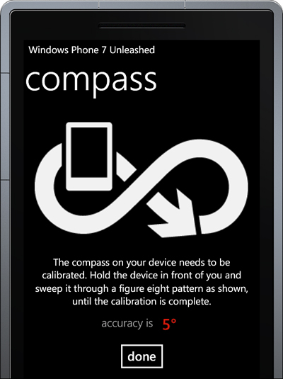
Figure 14.6. CompassView page showing calibration instructions
The compass sensor enables you to easily add heading information to your app, and to build specialized apps that can detect changes in magnetic forces around the device.
Sensing Rotation with the Gyroscope
The gyroscope is an optional hardware sensor that can sense rotation. While the accelerometer is able to gauge the orientation of the phone when it is stationary, it is not able to sense rotation. If the device is in free fall, the accelerometer reading is theoretically zero. In contrast, the gyroscope measures the rate of rotation around a particular axis, so that while the device continues to be in rotation the reading is non-zero. The disadvantage, however, is that because the gyroscope measures rotational velocity, and not position, it is subject to drift.
The sample code for this section creates a page that displays raw readings from the gyroscope, as well as providing a visual representation of the angular rotation of the device.
The sample code for this section is located in the /Sensors/Gyroscope/ directory of the WindowsPhone7Unleashed.Examples project in the downloadable sample code.
Using the Gyroscope Sensor
The gyroscope sensor is not a required component of Windows Phone devices. It is therefore important to verify that it is supported before attempting to use it. For this, the static Gyroscope.IsSupported property is used, as demonstrated in the GyroscopeViewModel class (see Listing 14.9). The Start method of the GyroscopeViewModel oversees the creation of the Gyroscope instance.
The default value of the Gyroscope’s TimeBetweenUpdates property is 20 milliseconds, which on my test device was the minimum allowed value.
As with all sensor types, the CurrentValueChanged event is used to receive periodic updates from the sensor.
Listing 14.9. GyroscopeViewModel.Start Method
public void Start()
{
if (!Gyroscope.IsSupported)
{
MessageService.ShowMessage(
"Gyroscope is not supported on this device.");
return;
}
gyroscope = new Gyroscope();
gyroscope.TimeBetweenUpdates = TimeSpan.FromMilliseconds(20);
gyroscope.CurrentValueChanged += HandleGyroscopeCurrentValueChanged;
gyroscope.Start();
}
When the CurrentValueChanged event is raised, the event handler receives a SensorReadingEventArgs<GyroscopeReading> object. GyroscopeReading contains two properties: a Timestamp property of type DateTimeOffset, which indicates when the sensor reading was taken, and a RotationRate property of type Vector3, which retrieves the rotational velocity around each axis of the device (X, Y, and Z) in radians per second.
The handler for the compass’s CurrentValueChanged event in the GyroscopeViewModel converts the RotationRate property of the event arguments, which is of type Vector3, to a custom ThreeDimensionalVector instance and assigns it to the viewmodel’s RotationRate property (see Listing 14.10).
The viewmodel tracks the angular rotation of the device by accumulating the value of each reading into a ThreeDimensionalVector called cumulativeRotationRadians. The amount of rotation since the last CurrentValueChanged event is calculated by multiplying the rotation rate by the time since the last event was raised. Put simply: (radians/second) * secondsSinceLastReading = radiansSinceLastReading.
Listing 14.10. HandleGyroscopeCurrentValueChanged Method
void HandleGyroscopeCurrentValueChanged(
object sender, SensorReadingEventArgs<GyroscopeReading> e)
{
GyroscopeReading reading = e.SensorReading;
Vector3 rate = reading.RotationRate;
RotationRate = new ThreeDimensionalVector(rate.X, rate.Y, rate.Z);
if (lastUpdateTime.Equals(DateTimeOffset.MinValue))
{
lastUpdateTime = e.SensorReading.Timestamp;
cumulativeRotationRadians = rotationRate;
return;
}
TimeSpan timeSinceLastUpdate = e.SensorReading.Timestamp - lastUpdateTime;
cumulativeRotationRadians
+= rotationRate * (timeSinceLastUpdate.TotalSeconds);
CumulativeRotation = new RotationAngles(
MathHelper.ToDegrees((float)cumulativeRotationRadians.X),
MathHelper.ToDegrees((float)cumulativeRotationRadians.Y),
MathHelper.ToDegrees((float)cumulativeRotationRadians.Z));
lastUpdateTime = e.SensorReading.Timestamp;
}
The viewmodel’s CumulativeRotation property is of type RotationAngle, a simple custom class with three readonly properties: X, Y, and Z, all of which are of type double.
As with most of the examples in this chapter, the page calls the viewmodel’s Start method within its OnNavigatedTo method and calls the Stop method within its OnNavigatedFrom method.
The Stop method of the viewmodel disposes the Gyroscope instance, as shown:
public void Stop()
{
if (gyroscope == null)
{
return;
}
gyroscope.Stop();
gyroscope.CurrentValueChanged -= HandleGyroscopeCurrentValueChanged;
gyroscope.Dispose();
gyroscope = null;
}
The GyroscopeView page contains TextBlock elements that display both the raw reading values in radians/second and the accumulated angular rotation values in degrees.
The cumulative rotation values serve to rotate colored rectangles. As the device is rotated, a RotateTransform is applied to each rectangle, as shown:
<Canvas Width="400" Height="400" Margin="0,50,0,0">
<Ellipse Width="400" Height="400" StrokeThickness="2"
Stroke="{StaticResource PhoneSubtleBrush}" />
<Rectangle Canvas.Left="195" Canvas.Top="0"
Width="10" Height="200" Fill="Honeydew">
<Rectangle.RenderTransform>
<RotateTransform Angle="{Binding CumulativeRotation.X}"
CenterX="5" CenterY="200" />
</Rectangle.RenderTransform>
</Rectangle>
<Rectangle Canvas.Left="195" Canvas.Top="0"
Width="10" Height="200" Fill="Red">
<Rectangle.RenderTransform>
<RotateTransform Angle="{Binding CumulativeRotation.Y}"
CenterX="5" CenterY="200" />
</Rectangle.RenderTransform>
</Rectangle>
<Rectangle Canvas.Left="195" Canvas.Top="0"
Width="10" Height="200" Fill="Orange">
<Rectangle.RenderTransform>
<RotateTransform Angle="{Binding CumulativeRotation.Z}"
CenterX="5" CenterY="200" />
</Rectangle.RenderTransform>
</Rectangle>
</Canvas>
Figure 14.7 shows the GyroscopeView page with the rotation of the device across three dimensions indicated by the three colored lines.

Figure 14.7. GyroscopeView page
You may notice, while running the sample, that the cumulative rotation drifts over time. This drift is indicative of the main disadvantage of the gyroscope; the gyroscope measures changes in angular rotation, and not the absolute angular rotation of the device. This is where the Accelerometer has an advantage, as it can provide the same rotational information without drift. In the case of the accelerometer, however, the magnitude of the signal is biased by gravity. This is not the case with the gyroscope.
The next section explores the Motion class, which promises to overcome the disadvantages of the individual sensors by unifying them into a single software virtual sensor.
Improving Sensor Accuracy with the Motion Sensor
The Motion class provides access to a virtual sensor. There is no dedicated motion sensor per se, rather the motion API combines the readings of the accelerometer, compass, and gyroscope to provide an enhanced API that overcomes the shortcomings of the individual sensors. The motion sensor provides the greatest accuracy of all the sensors, eliminating possible sensor inaccuracy issues that occur when relying on a single hardware sensor. For this reason, it is recommended that the motion sensor is used when available.
As mentioned in the previous section, the gyroscope is subject to drift. The motion API alleviates the drifting of the gyroscope by combing its readings with the compass and accelerometer readings.
Accelerometer readings include the force of gravity applied to the device as well as the force resulting from the motion of the device. The motion API separates the gravity vector from the device acceleration and provides you with the device’s attitude, consisting of yaw, pitch, and roll.
The Motion API can use two different sensor modes: normal and enhanced. Normal mode uses the compass and the accelerometer sensor and is less accurate than enhanced mode, which uses the compass, the accelerometer, and the gyroscope (see Table 14.2).
Table 14.2. Motion Sensor Availability

If your app requires the accuracy of enhanced mode, you should verify that the device supports the gyroscope sensor. If the gyroscope is supported then enhanced mode is used automatically.
Determining whether a device supports all the sensors required by your app happens before the app is deployed to the device. When a user views an app on Windows Phone Marketplace, a warning is issued if the user’s device does not support a sensor that is used by the app.
The Marketplace uses the compass sensor to determine whether the motion API is supported on a device. If a user views an app that uses the motion API and her device lacks a compass, a warning is displayed stating that the application requires a compass sensor.
Using the Motion Sensor
The sample code for this section follows the same pattern as the code for the gyroscope. The viewmodel’s Start method first tests whether the motion sensor is supported, and then creates a new Motion instance, subscribes to its CurrentValueChangedEvent, and calls its Start method. See the following excerpt:
public void Start()
{
if (!Motion.IsSupported)
{
MessageService.ShowMessage(
"Motion is not supported on this device.");
return;
}
motion = new Motion();
double interval = motion.TimeBetweenUpdates.TotalMilliseconds;
motion.CurrentValueChanged += HandleMotionCurrentValueChanged;
motion.Start();
}
The Motion sensor’s TimeBetweenUpdates property is, by default, set to 17 milliseconds.
When the CurrentValueChanged event is raised, a SensorReadingEventArgs<MotionReading> object is passed to your event handler. MotionReading reading contains the following properties:
• Attitude (of type AttitudeReading)—Gets the attitude (yaw, pitch, and roll) of the device, in radians
• DeviceAcceleration (of type Vector3)—Gets the linear acceleration of the device, in gravitational units
• DeviceRotationRate (of type Vector3)—Gets the rotational velocity of the device, in radians per second
• Gravity (of type Vector3)—Gets the gravity vector associated with the Microsoft.Devices.Sensors.MotionReading
• Timestamp (of type DateTimeOffset)—Gets the time at which the reading was calculated
The Attitude reading is useful in allowing you to determine the position of the device, which is broken down into pitch, roll, and yaw. Table 14.3 describes each of the AttitudeReading properties.
Table 14.3. AttitudeReading Struct Properties

The CurrentValueChanged handler, within the viewmodel, assigns the reading to various properties within the viewmodel. The reading’s DeviceAcceleration and DeviceRotationRate Vector3 properties are converted to a ThreeDimensionalVector using an extension method. See the following excerpt:
void HandleMotionCurrentValueChanged(
object sender, SensorReadingEventArgs<MotionReading> e)
{
MotionReading reading = e.SensorReading;
AttitudeReading = reading.Attitude;
DeviceAcceleration
= reading.DeviceAcceleration.ToThreeDimensionalVector();
DeviceRotationRate
= reading.DeviceRotationRate.ToThreeDimensionalVector();
Gravity = reading.Gravity.ToThreeDimensionalVector();
AttitudeReading attitude = reading.Attitude;
Attitude = new ThreeDimensionalVector(
attitude.Pitch, attitude.Roll, attitude.Yaw);
}
Within the view the reading vector values are represented in the same manner as for the gyroscope; lines are rotated using a RotateTransform that is bound to the reading value. In this case, however, values are supplied in radians and must be converted to degrees. For this, a custom IValueConverter called RadiansToDegreesConverter is used (see Listing 14.11).
Listing 14.11. RadiansToDegreesConverter Class
public class RadiansToDegreesConverter : IValueConverter
{
public object Convert(
object value, Type targetType, object parameter, CultureInfo culture)
{
float f = System.Convert.ToSingle(value);
float result = MathHelper.ToDegrees(f);
return result;
}
public object ConvertBack(
object value, Type targetType, object parameter, CultureInfo culture)
{
float f = (float)value;
float result = MathHelper.ToRadians(f);
return result;
}
}
A ControlTemplate is used to display the four ThreeDimensionalVector objects on the page. A Rectangle represents each vector component, and the RadiansToDegreesConverter, defined as page level resource, converts the source value to degrees for the RotateTransform. See the following excerpt:
<Rectangle Canvas.Left="195" Canvas.Top="0"
Width="10" Height="200" Fill="Honeydew">
<Rectangle.RenderTransform>
<RotateTransform Angle="{Binding X,
Converter={StaticResource RadiansToDegressConverter}}"
CenterX="5" CenterY="200" />
</Rectangle.RenderTransform>
</Rectangle>
Figure 14.8 shows the various readings displayed on the MotionView page. The attitude meter shows the pitch, roll, and yaw as the vector components X, Y, and Z, respectively. The other three reading types—acceleration, rotation rate, and gravity—are also displayed.
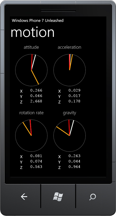
Figure 14.8. MotionView page
The Motion class also includes a Calibrate event that indicates when the compass needs calibrating. This event provides your app with the opportunity to display the calibration dialog, as discussed previously in the “Measuring Direction with the Compass” section of this chapter.
Summary
This chapter examined each Windows Phone sensor in detail, beginning with the accelerometer. You saw how to process accelerometer readings, and how to simulate acceleration within the Windows Phone emulator. The chapter explored how to apply data smoothing to accelerometer readings to decrease jittering of UI elements without sacrificing responsiveness. You also learned how to calibrate the accelerometer, and how to perform shake detection using the accelerometer.
The chapter then looked at the compass sensor and explained how to use the compass’s magnetic heading to build a custom compass app that displays the heading using an arrow. The chapter also discussed compass calibration.
The chapter then moved to the gyroscope sensor, and you saw how to build a UI to display the angular rotation of the phone.
Finally, the chapter examined the motion sensor, which is a virtual sensor that harnesses the hardware sensors to improve accuracy and provide extended orientation and motion information.