The projects that you’ve encountered thus far have used GPIO pins to turn LEDs on or off. But what if you wanted to control the brightness of an LED? Given that you can only turn pins on (high: 3.3V) or off (low: 0V), you have no way to send less power to the LED; the lower the power, the dimmer the LED. If you consider solutions (or features) of devices that are sensitive to ambient light—such as a backlit keyboard—you may have noticed it changes brightness as the room becomes darker. In this project, you’re going to explore how such a feature works. That is, you’re going to build a fancy LED nightlight.
Unlike the last project, this project is a bit more complex in concept. You must measure the ambient light in the room and then calculate how much power to send to the LED using a technique called pulse-width modulation (PWM). You will also use the same analog-to-digital converter (ADC) and SPI interface from the last project, but you will implement it in a slightly different way. Let’s get started.
Although this project is written in C#, other than the syntax and mechanics of building, the concepts of using a class are similar in C++ and Visual Basic.
Overview
You will design and implement an LED nightlight using a light-dependent resistor (LDR, also called a photocell or photoresistor )1 read from an ADC (the LDR is an analog component like a potentiometer). The LDR is a special resistor that changes resistance depending on the intensity of ambient light.
You need to use the ADC because you want to read analog values, and the Raspberry Pi (and many other boards) does not have analog-to-digital logic. That is, the GPIO pins are digital only. The ADC acts like a “bridge” between digital and analog devices. You will use the MCP3008 that you used in the last chapter.
The real trick to this solution is you must use a special library (namespace) in order to access the pulse-width modulation features of your Raspberry Pi. The library you will use is a contributed library and not part of the standard Visual Studio built-in libraries for Windows 10 IoT Core. However, the library isn’t difficult to install, and you will reuse the class you built in the last chapter as the basis for implementing a class for controlling an LED (fading), as well as the ADC. The library is named the Microsoft IoT Lightning Provider (also called the Lightning software development kit or SDK).
In order to use the Lightning SDK, you need Windows 10 IoT Core Version 10.0.10586.0 or later.
Since the LDR responds to light and the ambient light can vary, you will also use a simple user interface to allow you to adjust the sensitivity of the light sensor by restricting its range. That is, you will be able to set the minimum and maximum values for the range. Thus, you will be able to tune the solution to fit the ambient light levels.
Let’s look at the components that you need and then see how to wire everything together.
Required Components
(1) LED (any color)
(1) 10K ohm resistor
(1) 150 ohm resistor (or appropriate for your LEDs)
(1) light-dependent resistor (photocell)—LDR
MCP3008 ADC chip
Jumper wires: (5) male-to-male, (8) male-to-female
Breadboard (full size recommended but half size is OK)
Raspberry Pi 2 or 3
Power supply
Monitor
Keyboard and mouse
Set Up the Hardware
Connection Map for Power Meter Project
GPIO | Connection | Function | Notes |
|---|---|---|---|
3.3V (1) | Breadboard power rail | Power | |
5V (2) | 10K resistor | Power to LDR | |
GND (6) | Breadboard ground rail | GND | |
MOSI (19) | SPI | MCP3008 pin 11 | |
MISO (21) | SPI | MCP3008 pin 12 | |
SCLK (23) | SPI | MCP3008 pin 13 | |
CC0 (24) | SPI | MCP3008 pin 10 | |
27 | LED | Resistor for LED |
Connections on the Breadboard
From | To | Notes |
|---|---|---|
Breadboard GND | LDR | |
Breadboard power | ADC VDD (MCP3008 pin 16) | |
Breadboard power | ADC VREF (MCP3008 pin 15) | |
Breadboard GND | ADC AGND (MCP3008 pin 14) | |
Breadboard GND | ADC GND (MCP3008 pin 9) | |
LDR | ADC Channel 0 (MCP3008 pin 1) |
See Chapter 9 for details on how to determine the correct resistor for your LED.
Once again, I am cheating a bit by using the Adafruit GPIO Reference Card for Raspberry Pi 2 or 3 (www.adafruit.com/products/2263), which makes locating GPIO pins much easier than counting pin numbers.
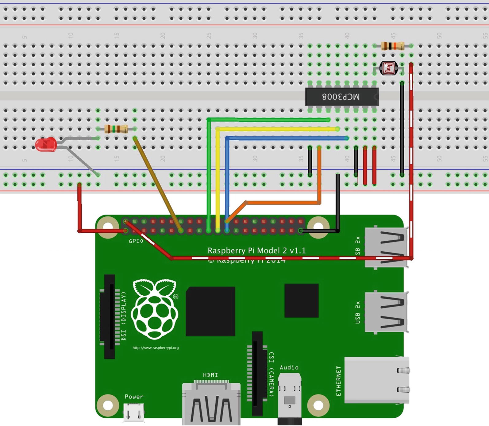
Connections for the nightlight project
Notice how the LDR and 10K resistor are configured. This is not a mistake. You want the resistor to connect to the second leg of the LDR and the LDR connecting to the channel 0 pin of the ADC as a pull-up resistor. Also note how power to the LDR comes from the 5V pin (2) on the GPIO. The SPI connections are the same as the last project.
IoT devices such as the Raspberry Pi can switch between exactly two voltages on their GPIO pins (0.0V or 3.3V). The problem is that many components can operate on a range of voltages. For example, a fan can rotate at different speeds based on the current fed to it. The higher the current, the faster the fan spins. The same is true for other components, such as LEDs, servos, and motors.
It is possible to simulate sending different current levels to a component using a technique called pulse-width modulation (PWM) . The process works by rapidly switching a pin (line) on and off at different frequencies (hence the pulse) for a given very short period of time (hence the width). The end effect is the device appears to be operating at lower voltages. For example, if you want only 3.0V from 3.3V, you must set the pin to operate at 90% or the pin will be on (through pulsing) at most 90% of the time.

This shows a voltage source (V) modulated as a series of pulses creating a sine-like wave. The result is a sine-like current in the inductor (B). The current waveform is the integral of the voltage waveform. While this sounds all scientific/mathematical, just remember PWM is a technique for simulating different current values by turning the pin on and off rapidly in a specific pattern.
If you are following along with this chapter working on the project, go ahead and make the hardware connections now. Don’t power on the board yet but do double- and triple-check the connections.
Write the Code
Now it’s time to write the code for our example. Since you are working with several new concepts as well as a new component, I will introduce the code for each in turn. I’ve decided to use C#, but you could implement this project in C++.
Since you have learned all the basics of creating projects in Visual Studio, including how to build and deploy applications, I omit the details of the common operations for brevity.
The project uses an LDR to measure ambient light read via an ADC (MCP3008); the value read is used to control the percentage of current sent to an LED via PWM. Unfortunately, while the IoT devices you have for Windows 10 IoT Core have PWM support, Windows 10 IoT Core has only rudimentary support for PWM. Fortunately, there is an add-on library called the Microsoft IoT Lightning Providers that get you what you need to create a PWM output on a GPIO pin.
I like to use modularization to help make the code easier to write and maintain. It also helps to focus your efforts by concentrating on a specific concept to model. You will see this as you walk through the code. You will create a class for the ADC and a class for the PWM control of the LED. Finally, you use the DispatcherTimer class to periodically check the LDR and set the PWM percentage for the LED.3
Let’s talk about starting a new project and adding the resources that you need first (e.g., the Microsoft IoT Lightning Providers), and then we will walk through the entire code.
New Project
The code in the MainPage() function initializes the components, the new LED fade class (fader), and the new MCP3008 class (adc). Each of these classes has an Initialize() method . There is also a method to initialize the lightning providers that must be called first. You will see this method in the next section.
MainPage Method
You need two references added to the solution. You need the Windows 10 IoT Extensions from the project property page. You do this by right-clicking the References item under the project in the Solution Explorer. You also need to install the Microsoft IoT Lightning Providers library. But first, we must turn on the lightning provider on our device.
Lighting Providers
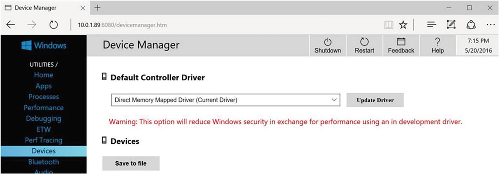
Setting the Direct Memory Mapped Driver on the Device Portal
When you select the direct memory mapped driver from the drop-down menu and click Update Driver, the portal warns you that the driver is a development-level prerelease and may not perform at peak efficiency. For our purposes, you can ignore the warning, as it has no bearing on the project. The device needs to reboot to complete the change.
You will receive a dialog to restart your device. If the device doesn’t restart, you can power off the device and power it back on. Once restarted, the device will be using the updated driver.
Remember , if you want to return your device to normal, you will have to go back to the Device Portal and change the drive back to Inbox Driver. Be sure to do that after you are finished with this project if you are not continuing on to Chapter 12.
You want to reverse this step once you have finished the project and before starting a new project that does not use the lightning library.
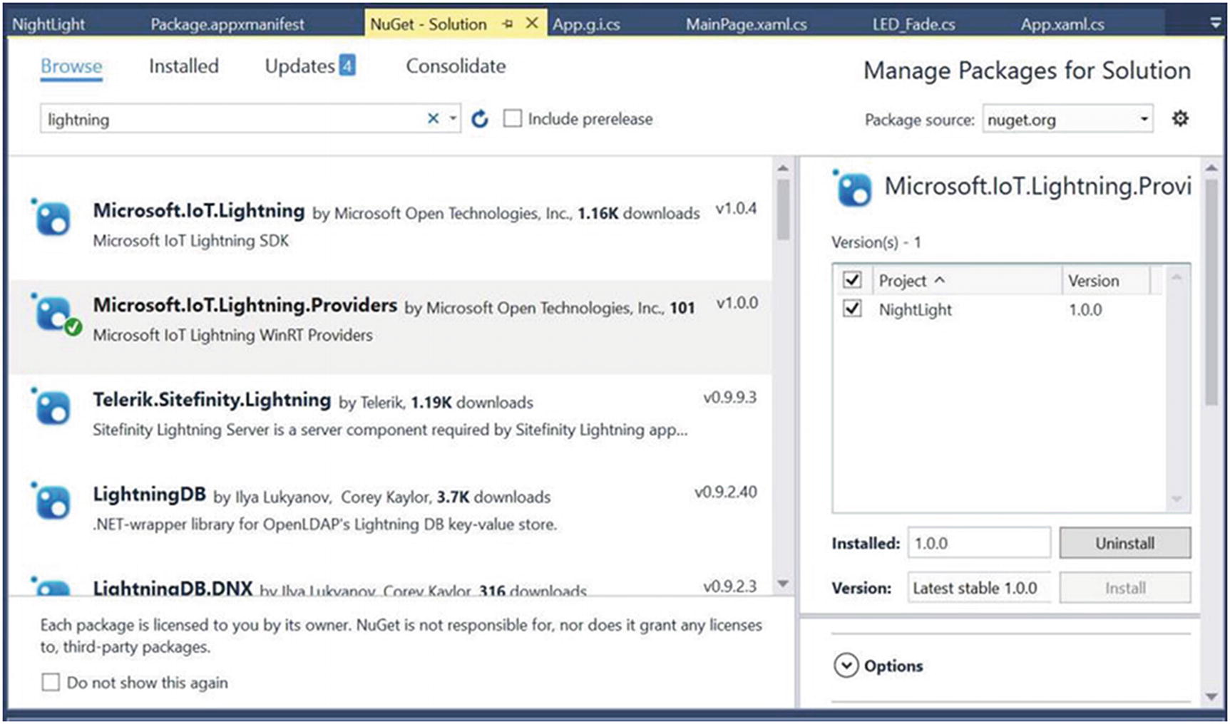
NuGet Package Manager
Select the entry named Microsoft.IoT.Lightning in the list, tick the project name (solution) in the list on the right, and finally click Install. The installation starts and you may get a confirmation dialog where you click OK to continue. Visual Studio downloads a number of packages and then asks your permission to install them. Go ahead and let the installation complete. A dialog box tells you when the installation is complete.
You can also download this library and install it manually if the NuGet manager fails. See https://docs.microsoft.com/en-us/windows/iot-core/develop-your-app/lightningproviders for more details.
Since this library isn’t integrated with Visual Studio or the Windows UWP libraries, you must make a small alteration to the project files to grant permission to use the library (reference) in the project. Failure to do this step leads to some strange execution issues (but it compiles without errors or warnings). More specifically, the InitLightningProvider() method fails because the LightningProvider.IsLightningEnabled property is False.
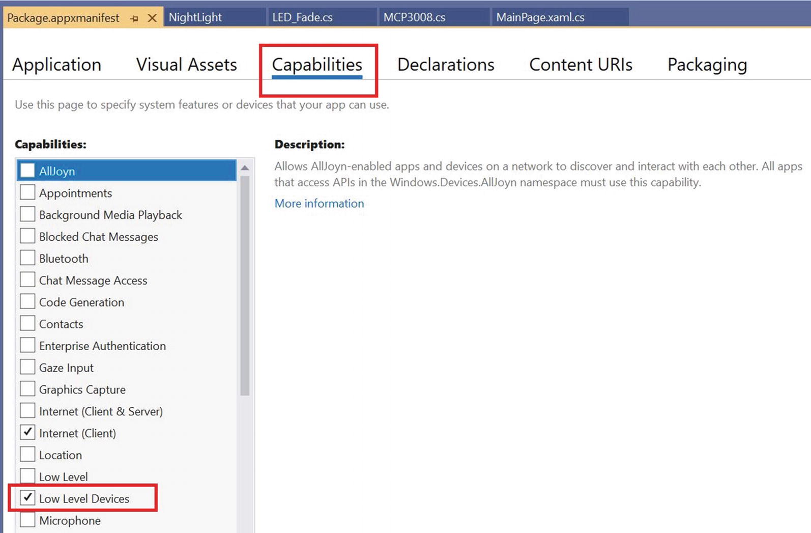
Enabling capabilities in package manifest
The bulk of the code for the SPI and PWM are contained in the new classes you will add shortly. But first, let’s implement the user interface and complete the MainPage class.
User Interface
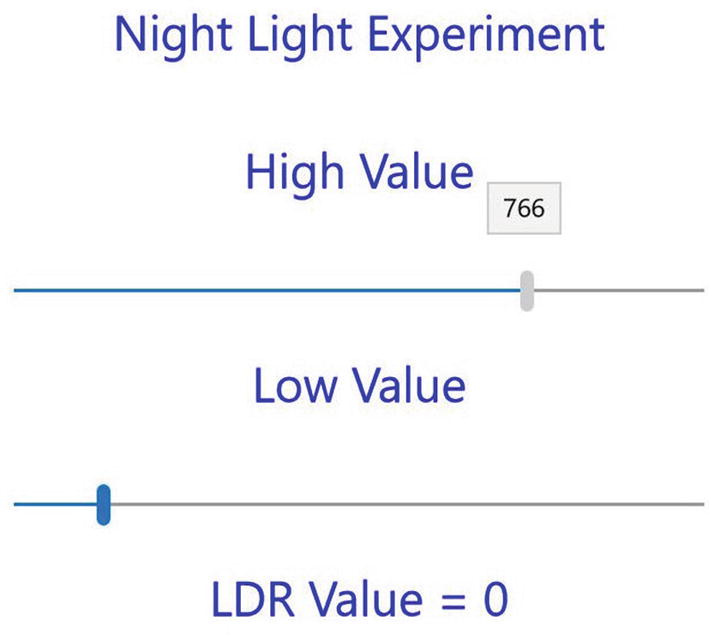
The user interface is deliberately simple consisting of only a few labels and two sliders. The sliders control the minimum and maximum values for the range of sensitivity for the LDR. One of the labels displays the value read from the LDR. You can use this value to help tune the fade effect.
That is, you can set the lower value to the value read during ambient light levels. This effectively sets the percent power to 0 where the LED is off (or very dim). You can use the higher value slider to set the maximum value for the scale. You can find out what that value is by placing your hand over the LDR and reading the value. Thus, you can tune the nightlight effect to match ambient light readings.
User Interface (XAML) Code
This code needs one extra step to ensure that you stay within the limits of the slider. See if you can spot it yourself. Hint: What happens when the high value is already at the highest setting? Although not essential for our experiment, you should strive to improve error handling to include the fringe values and conditions.
Now let’s see the code to read from the value of the LDR and fade the LED.
Controlling the LED
Timer Code
Wow, that’s a lot of code. For the most part, it is similar to the timer event from the last project. However, the calculation for the percentage to use for the PWM is new. Here, the percentage represents the brightness of the LED. The higher the percentage calculated means the faster the LED pulses and therefore appears brighter.
I have added an interesting bit of data at the end of the method. This demonstrates how to calculate the voltage that is flowing through the LDR. You may need this technique for any projects where you are reading analog voltage.
Take some time to read through the code. You will see a number of additional debug statements that you can use when testing the project in debug mode. There is code to update the label in the user interface with the value read and the voltage calculated. If you are curious, you can use a multimeter to measure the voltage on the ADC side of the LDR (positive lead on the LDR and negative lead on the ground). You should see the same voltage on the multimeter as shown in the user interface.
Now let’s see how to put all of these pieces together.
Completing the Main Class
MainPage Code Layout
Now let’s see how to create the code for the two new classes.
Code for the MCP3008
The code for the ADC class is very similar to the class you used in the last project. The difference is you will use the lightning providers to communicate with the ADC rather than the Windows 10 IoT extension. This is because the Windows 10 IoT extension and the lightning provider are incompatible. That is, you cannot use the same code from the last project together with the PWM code from the lightning provider. Fortunately, the lightning provider has SPI support.
Constructor—MCP3008(): Log instantiation with a debug statement
Initialize(): Initialize the SPI interface
getValue(): Read a value from the ADC on a specified channel
ADCToVoltage(): Return the voltage read for a specific value
The Initialize() Method
This method is very similar to the class that you used in the last project. The biggest difference is you can get the SPI device with a single class to the provider. This code is a pattern for the other providers in the Lightning Providers library. In fact, you see very similar code in the PWM class.
The getValue() method is the same as the class used in the project from Chapter 10 (the ADC_MCP3008.cs file). You can simply copy it from the last project and paste it in the new class. I omit the details from the list for brevity.
The MCP3008 Class Layout
Notice the last method. This is a helper method that you can use to calculate the voltage read from the channel. You used this in the MainPage class to display the voltage when the value is read from the LDR.
If you want to copy a class from another project, you can copy the file into the project folder and optionally rename the file. To add the class to the solution, right-click the project and choose Add ➤ Existing Item… and select the class file. If you renamed the class file, you may also have to rename the class itself as well as change the namespace to match the current project/solution.
Now let’s look at the code for the PWM class.
Code for the PWM
Constructor—LED_Fade(): Log instantiation with a debug statement
Initialize(): Initialize the PWM interface
set_fade(): Set the duty cycle (percentage of time the LED is on) for the GPIO (LED) pin
The Initialize() Method
This code is a bit different than the SPI code. In this case, you need to open a pin for controlling the PWM and set the starting duty cycle (percent). In this case, you set it to 0, which effectively turns off the LED. Finally, you start the PWM class.
The LED_Fade Class Layout
That’s it! The code is complete and ready for compilation. Be sure to check the prior listings to ensure that you have all the code in the right place. Once you have entered all the code, you should then attempt to compile the code. Correct any errors that you find until the code compiles without errors or warnings.
Deploy and Execute
Now it is time to deploy the application! Be sure to fix any compilation errors first. You may want to compile the application in debug first (but you can compile in release mode if you’d prefer). In fact, in order to see the debug messages, you will need to be using the debug build.
Target device: Remote Machine
Remote Machine: The name of your device
(Optional) Uninstall and then re-install: Checked
(Optional) Deploy optional packages: Checked
Application process: Managed Only
Background task process: Managed Only
Once you make any changes in this dialog, be sure to save your solution. Building or deploying does not automatically save these settings.
We should also change the package name in the package manifest. Recall from Chapter 6 (see the “Deploying Your Application (No Debugging)” section and Figure 6-9), we can change the package name. Do that now so you can find your application easier in the Device Portal.
Example Debug (Output Window)
Of course, you can run the application by starting it on your device using the Apps pane. You use the small triangle or arrow next to the application name to start it and the square icon to stop it or the trashcan icon to delete the application.
If everything worked correctly, you should be able to place your hand over the LDR and see the LED brighten. If it doesn’t (and there is a good chance it won’t), don’t worry. Conduct an experiment by clearing away anything that can cast a shadow on the LDR and take note of the value in the user interface. Let it run for a few minutes and note the values. You should see it bounce around a bit but should settle to within about 20–30 of normal. For example, in my office, the ambient light level value was about 220. Next, place your hand over the LDR and note the change in value. Let the values settle and note the value range. In my office, the value was about 450.
Now, adjust the high value slider to the value when your hand was over the LDR and the low value to the value for ambient light. Once set, you can experiment with the LED brightness by slowly placing your hand over the LDR. The LED should go from a very dim setting to full (or nearly) brightness. It may take some additional runs to fine-tune the high and low values, but once set, the project acts as a light-sensing nightlight. How cool is that?
Summary
IoT solutions often require using analog components. Moreover, you may need to control analog components by adjusting the voltage to the component. This often requires using additional libraries and features that may not be in the standard libraries. In this case, you had to use a special library named the Microsoft IoT Lightning Providers to get access to PWM and SPI interfaces.
You saw a number of new things in this project, including another way to use an ADC with an SPI interface, how to read values from an LDR, and how to use PWM to control the brightness of an LED. While the project itself is rather simplistic, the code clearly was not, and it was a bit more code than you’ve seen so far.4
The next chapter continues the set of example IoT projects that you can use to learn more about building IoT solutions. You learn how to write code to read more sensors. In Chapter 12, you create a project to report weather data from several sensors, and then in Chapter 13, you learn how to collect and store the data generated.