
Some of the more interesting IoT solutions are those that implement actionable devices or features that allow you to control hardware remotely. This could be controlling a remote control toy (car, truck, drone), moving a camera (pan, tilt, zoom), opening or closing a gate, and so forth or simply controlling lights or locks remotely.
That’s the real key and trick to the solution—making the solution available remotely. One of the best ways to do that is to use networking protocols running on the device and control it using an application on another PC or device (via the user interface). More specifically, you implement a server that supports actions (events) that allow you to control the actionable devices, lights, locks, and so forth from a client.
In this chapter, you will see one method for building IoT solutions that control hardware remotely using TCP sockets. You have already discovered the tools and techniques for turning LEDs on/off, reading data from sensors, and implementing PWM-controlled devices.
Unlike previous projects, the code for this project is not overly complicated, but it is different from the techniques you’ve seen. That is, you will use C# and a library from NuGet to remotely control hardware. There is an optional part that requires some soldering and cutting or drilling to assemble, making the hardware for this project a bit more complicated than previous projects. Regardless, you can take the concepts presented and make all manner of interesting solutions. Let’s get started.
Overview
Available: You are available.
Do not disturb: You do not want to be interrupted.
Out to lunch: You are away from your desk on lunch break.
Be back later: You are away from your desk but expect to return.
Gone for the day: You are not returning to your desk until the next business day.
A servo operates with pulse-width modulation (PWM).2 That is, the faster the pulses you send it, the more (further) it will rotate. Typically, you would choose specific patterns to move the servo to one of several positions. Servos are used in all manner of solutions from mechanical movements in toys, robots, remote control planes, cars, and even 3D printers. Basically, if you need a small motor to move a lever, rotate something, steer, or move something in a precision manner, you may want to use a servo.
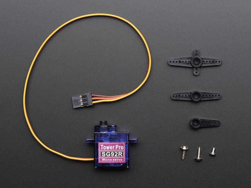
Micro servo (courtesy of Adafruit)
As you can see in the photo, servos typically come with a number of arms you can use to connect a thin wire or rod from the servo to another component that you want to move. Servos have a range of motion of 90 degrees. A special form of servo—called a continuous rotation servo—can rotate 360 degrees. For this project, the normal 90-degree range of motion is all that you need.
When you use a servo, you must discover the positions you want for the feature. For example, in this project, you simply want to raise a flag, so you need to know only two positions: one for when the flag is down and one for when the flag is raised. To do this, you need to know how to use PWM in your projects. Fortunately, you have seen an example of how to do this. Recall that you saw how to use PWM in Chapter 11. However, you’re going to cheat a little and use a nifty new product from SparkFun called a Servo Trigger (www.sparkfun.com/products/13118).
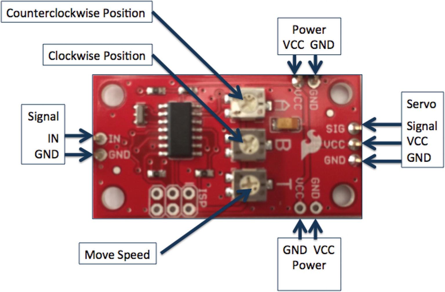
Servo Trigger from SparkFun
On the left is the signal connector with only two wires—a ground and signal. On the right is the connector for the servo. On the top and bottom are power connectors for the servo. This allows you to power the servo using 5V (most servos can operate on 3–9V). There are two connectors so that you can wire several Servo Triggers in series, so you can use less wire for connecting power.
While the Servo Trigger makes using a servo for this project really easy, it does not come with any headers soldered. Thus, you will have to solder headers to the board. At a minimum, you need male headers on the signal, one of the power connections, and the servo connector. Soldering is not difficult, but if you do not know how to solder, ask a friend to help you. If nothing else, you now have a really good reason to learn how to solder!
The Servo Trigger is customized via the programming interface. See the product site on SparkFun for a complete guide (called the hookup guide).
Servo Wires
Ground (Pin 1) | Power (Pin 2) | Signal (Pin 3) |
|---|---|---|
Black | Red | White |
Black | Brown | Yellow |
Black | Brown | White |
Black | Red | Yellow |
Brown | Red | White |
Brown | Orange | Yellow |
To learn more about servos, see jameco.com/jameco/workshop/howitworks/how-servo-motors-work.html.
You will also use a number of LEDs to indicate a message for your coworkers. That is, when the LED is on, it indicates the current state. For example, if the flag is set to IN and the LED for “Do not disturb” is turned on, you are in the office but working on things that require your attention (such as a phone call or similar meeting) and do not want to be interrupted.
Finally, you will use C# to write two solutions: a server that runs on the device and an application that runs on your PC that, together, allow you to control the hardware.
What you should gain from this project is how to write small applications to control hardware via TCP sockets, how to use a servo (with help from SparkFun), and how to create specialized network-based solutions in Windows 10 IoT Core.
The really fun part of this project is building the sign itself. You have two options: (1) build the circuit on the breadboard, which allows you to explore all the basic concepts without the extra work, or (2) build the solution in an enclosure using a simple cardboard box that you can mount the LEDs, servo, and flag. You can hang this box on your cubical wall so that visitors can see your office status at a glance. However, this option does require a bit of soldering.
I present both options; thus, I recommend doing the first (on a breadboard) and then later build the solution in an enclosure. But first, let’s look at the hardware needed for this project.
Required Components
SparkFun Servo Trigger (www.sparkfun.com/products/13118)
Servo (www.adafruit.com/products/169 or www.sparkfun.com/products/9065)
(4) red LEDs
(1) green LED
(5) 150 ohm resistors
Jumper wires: (10) male-to-female, (1) male-to-male
Breadboard (full size recommended but half size is OK)
Raspberry Pi 2 or 3
Power supply
The servo mount and flag are available in the source code download. They are 3D printer STL files that you can download and print or have printed for you using a 3D printing service.
Set Up the Hardware
Connection Map for Out-of-Office Project
GPIO | Connection | Function | Notes |
|---|---|---|---|
5V (2) | Power for Servo Trigger | Power to breakout board | |
GND (6) | Ground for Servo Trigger, LEDs | GND on breakout board | |
20 | Servo Trigger Signal | Engage Servo | |
21 | Green LED | LED on | |
22 | Red LED #1 | LED on | |
23 | Red LED #2 | LED on | |
24 | Red LED #3 | LED on | |
25 | Red LED #4 | LED on |
Connections on the Breadboard
From | To | Notes |
|---|---|---|
Breadboard GND Rail#1 | Breadboard GND Rail#2 | |
Breadboard Power | Servo Trigger VCC | |
Breadboard GND | Servo GND (power in) | |
Breadboard GND | Servo GND (signal) | |
Servo | Servo Trigger servo header |
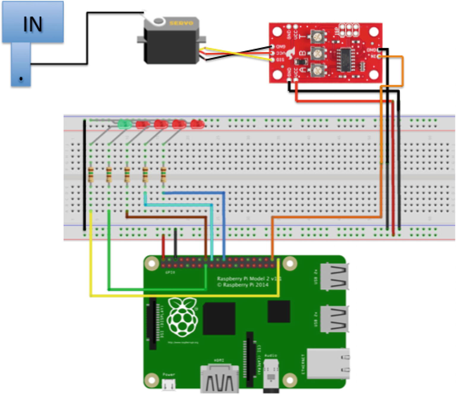
Connections for the out-of-office project
Here, you see the breadboard implementation of the project. Recall from earlier discussions, this is how most projects start out—as a set of circuits implemented on a breadboard before being transferred to an enclosure, a printed circuit board designed, and so forth.
There are GPIO connections for each of the LEDs with the negative lead plugged into the breadboard for each LED. You also see a GPIO pin for the Servo Trigger as well as power connections for the Servo Trigger and ground for the LEDs. Lastly, you see the servo depicted connected to the Servo Trigger and an arm connected to the flag to raise and lower it on command.
If you are following along with this chapter working on the project, go ahead and make the hardware connections now. Don’t power on the board yet but do double- and triple-check the connections.
SparkFun has a really neat adapter for working with the GPIO header on a Raspberry Pi with a breadboard. It’s called a Raspberry Pi Wedge (www.sparkfun.com/products/13717). It comes with a 40-pin ribbon cable that you connect to your Raspberry Pi, thereby allowing you to position the Raspberry Pi farther away from the breadboard or simply reposition the device without disturbing the breadboard circuits.

If you use this device, you can save yourself some time looking for the correct GPIO pin since they are clearly marked on the board (but they are not in the same order as the GPIO header on the board but, in my opinion, grouped together a bit more logically).
Write the Code
Now it is time to write the code for the project. Since it is written in C#, it is very easy to follow; however, the networking portion is not as intuitive as some of the previous projects. Recall, we will create two projects: one for the server that runs on the device (Raspberry Pi) and another that runs on your PC (or another IoT device). Let’s begin with creating the server, walking through each of the parts that you need to implement. We’ll see the client solution in a later section.
Don’t worry if you’ve never written any code for working with networking protocols like TCP sockets. We’ll be using a special library that makes it very easy to use. As you will see, you only need to know the basics of socket programming.
For more information and a concise overview of network programming, see www.codeproject.com/Articles/10649/An-Introduction-to-Socket-Programming-in-NET-using or www.tutorialspoint.com/Socket-Programming-in-Chash.
Writing the Server Application
You will use a new project template. In this case, we want the application to run in the background, so we will use the C# Background Application (IoT) template. Use the name OfficeSignServer for the project name. You can save the project wherever you like or use the default location. The majority of the code for this project will be implemented in its of class named Server. But before we write that code, let’s add the resources we need for the project.
The resources required include two libraries we can get from NuGet. First, we need the EasyTcp library, which encapsulates the code needed to work with TCP sockets (making it very easy). We also need the System.Text.Json library, which enables us to work with JavaScript Object Notation (JSON3). Let’s see how to get and install each of these.
EasyTcp
EasyTcp is a library that supports working with TCP sockets. It also takes care of the low-level communication for you. All you need to do is instantiate the class and call the methods to read the data to/from the network. We will use version 3.6.3 of this library for this project. Newer versions may not work with the project code.
See https://github.com/Job79/EasyTcp to learn more about EasyTcp.
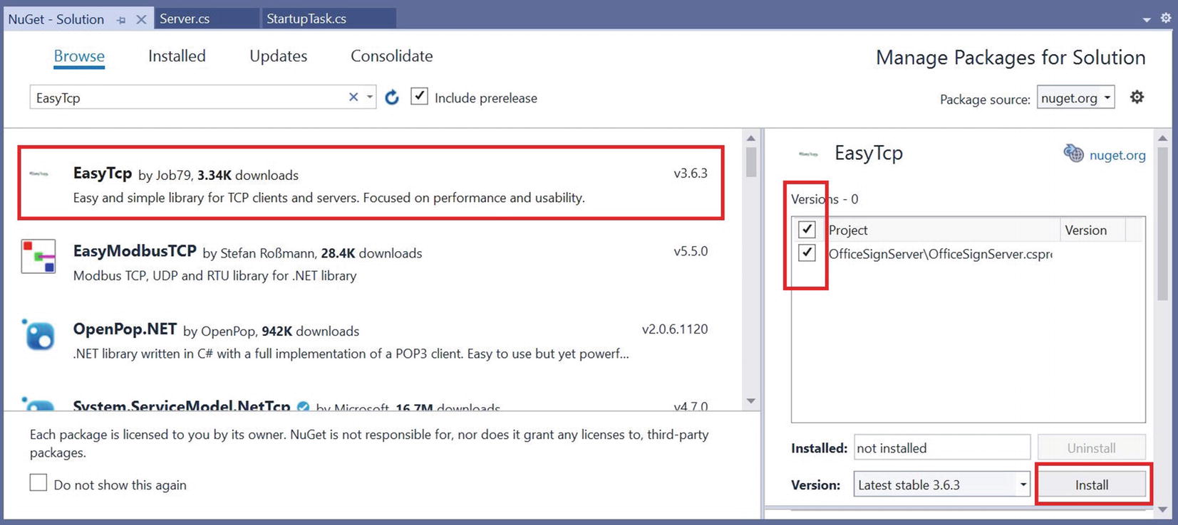
NuGet Package Manager, results for EasyTcp
Select the entry named EasyTcp in the list, choose version 3.6.3 in the Versions list, tick the project name (solution) in the list on the right, and finally click Install. The installation starts and Visual Studio downloads a number of packages and then asks your permission to install them. A dialog box will open to tell you that the installation is complete.
System.Text.Json
System.Text.Json is a library that supports JSON objects, which we will use for our communication protocol between the server and the client. That is, we will pass JSON data that has a command inside that tells the server how to control the hardware (the sign). Cool, eh?
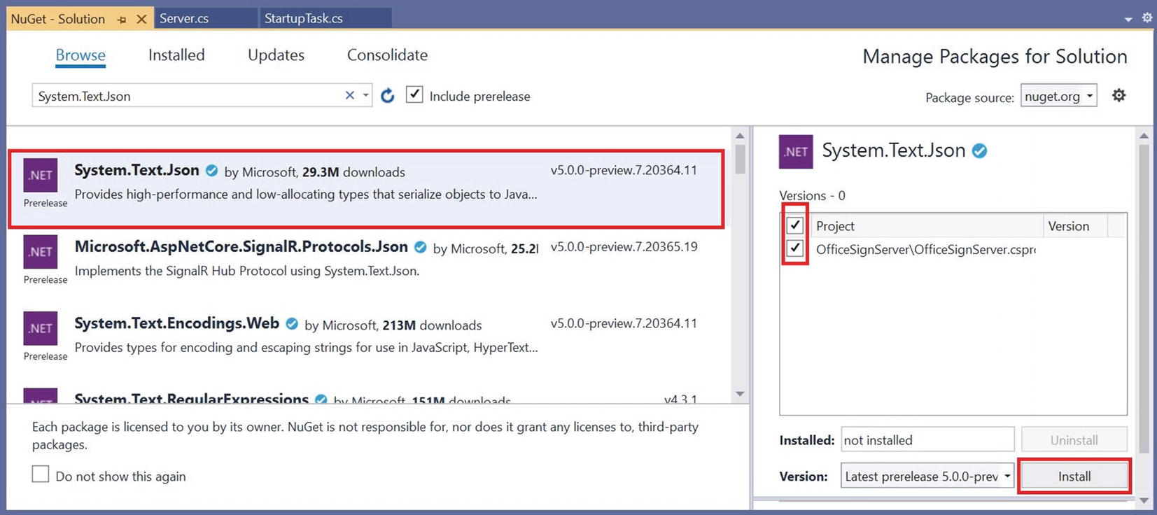
NuGet Package Manager, results for System.Text.Json
Select the entry named System.Text.Json in the list, tick the project name (solution) in the list on the right, and finally click Install. The installation starts and Visual Studio downloads a number of packages and then asks your permission to install them. Go ahead and let the installation complete. A dialog box will open to tell you that the installation is complete.
OK, now we have the references we need. Now, let’s write the code for the server class.
Server Class

Adding the Server class
Once the dialog closes, double-click the Server.cs file. This is where you put most of the code for the project for working with the TCP socket. We will also place the code for the GPIO interactions in this class since it doesn’t require many lines of code. If the project were more complex (or for your own projects), you may want to consider placing the GPIO code in its own class. This choice is typical of what a developer would encounter and is often a balance between convenience (all code in one class) and complexity, maintainability, or readability.
Notice we use the C# get and set directives to automatically generate the get() and set() methods for the class. This will come in handy later when we read the data from the client.
Server Class Constants and Variables
Next, we will need a few methods including a constructor, methods to set up the GPIO, start the server, and respond to incoming messages. Let’s look at each in turn.
Server Class Start Server Method
Notice there are two attributes: inOffice, which is a Boolean that we can use to set the flag, and location, which is an integer. The client sets the location based on the radio button chosen for the location. We use an integer starting with 0 so that it can be used to reference the LEDs in the array. That way, what is sent to the server matches the interface on the client. That is, when the radio button at array index 0 is ticked, LED index 0 is turned on. While this message is quite simple, it shows the power you can build into your client/server applications and the level of sophistication you can achieve to pass data.
Notice something familiar here? Yes, that’s right. The attributes in the JSON string are the same names as those in the embedded class we created earlier. If you’re thinking that is significant, it is! More on that in a moment.
Server Class Initialize GPIO Method
Finally, we add a method to process the messages from the client. We will name this method OnMessageReceived. This method is responsible for deciphering the message from the client by converting the JSON string into an instance of the OfficeStatus class. Yes, you do that! That’s part of what makes using JSON so nice—we can convert it to a C# class and call our get/set methods on it.
Server Class OnMessageReceived Method
Notice we used a loop to loop over the array of LEDs. We set them on or off depending on the value of the location attribute . If location is 0, the first LED is turned on and the reset turned off. Cool, eh?
Well, that’s the complete code for the Server class. Now, let’s look at the code for the base application, which is a special background task class known as the StartupTask.
StartupTask
StartupTask Class
But there is a trick here. Do you see it? Yes, it’s that deferral thing. It turns out, Windows 10 IoT Core will only allow a background task to run so long and then it gets stopped. To prevent that from happening, you can simply declare a variable of type BackgroundTaskDeferral and retrieve it with taskInstance.GetDeferral(). This will keep the operating system from closing the application after a timeout.
For more information about the background deferral, see https://docs.microsoft.com/en-us/uwp/api/windows.applicationmodel.background.backgroundtaskdeferral?view=winrt-19041.
Also, notice the use of the IP address 192.168.42.15 and port 13001. This information comes from your IoT device. It should match the IP address of where you plan to run the server (on your Raspberry Pi), not your PC. The port is largely arbitrary, but it should match the one you use in the client. In fact, we will see the same port and hostname (IP) when we look at the client application.
OK, now we’re ready to look at the client application.
Writing the Client Application
The client application is a Universal Windows application also written in C#, so we will use the C# Blank App (Universal Windows) template. Use the name OfficeSignClient for the project name. You can save the project wherever you like or use the default location or save it with the server project.
This application is similar to the server application with the addition of the user interface. We will use the same libraries and create a client class named Client. However, unlike the server application, there is no GPIO code in the Client class because there is no GPIO! Rather, we will have a user interface that we will use to form a message that is sent to the server. Thus, the client portion of the networking code is quite basic.
Rather than repeat the steps for installing the NuGet packages, refer to the preceding sections named “EasyTcp” and “System.Text.Json” to install the packages. Once that is done, you’re ready to code the client class.
Client Class
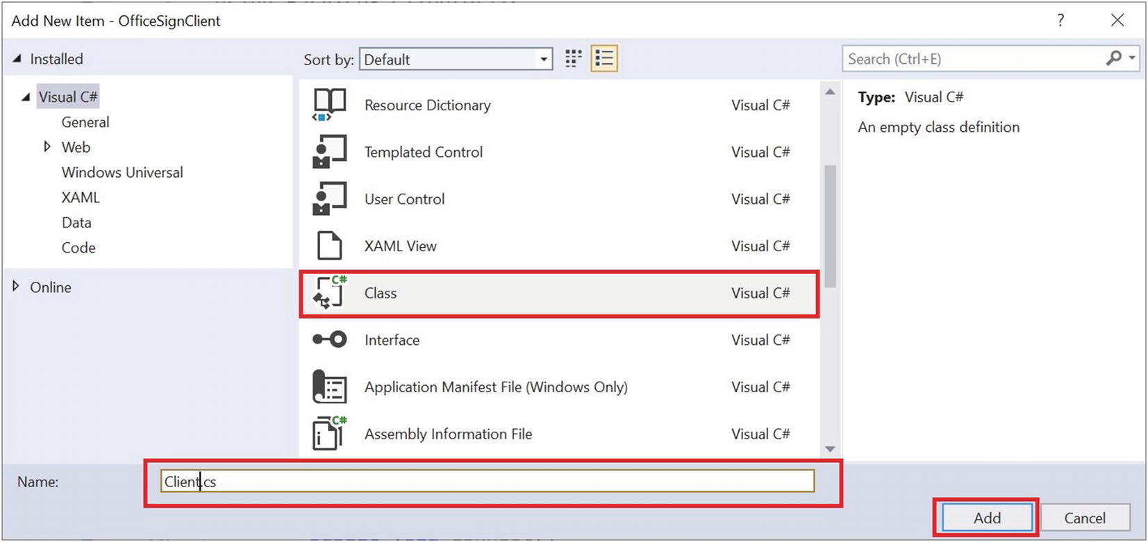
Adding the Client class
Once the dialog closes, double-click the Client.cs file. This is where you put most of the code for the project for working with the TCP socket. In this case, the class will simply send the message to the server. The user interface will be responsible for building the JSON string (message) to send to the server.
Connect Method for the Client Class
SendMessage Method for the Client Class
Now that the client class is complete, let’s look at the code for the user interface.
User Interface
User Interface for the Client Class
Now, to wire in the client class to send a message, we use the same embedded class we had in the server code to contain the message and use the “on” events for the radio button groups to set the values in the embedded class. We then send that message to the server each time it is updated (the status is changed).
MainPage Constructor for the Client Application
Make sure the host (IP) and port match those values you used in the server application. If they do not match, the client will not connect, and nothing will happen when you change the radio buttons in the user interface.
We are almost there. We need only two more methods: one for when the IN/OUT office radio buttons are changed and another for when the location radio buttons are changed. These methods are also straightforward in that we simply change the data in the instance of the OfficeStatus class and send the message to the server. Let’s look at the details of each method.
Recall from the XAML user interface, we named the IN/OUT group of radio buttons Status, so the event for when those buttons are changed will be named Status_Checked(). This method is fired as an event (in a thread) when any of the radio buttons in the group are changed (checked). When the method is fired (run), we need to do several things.
First, if the officeClient (the variable that contains the instance of the client class) is null, we do nothing (we return). This is necessary because, during startup, we set the initial values of the radio buttons and thus this method is fired, but this can occur before the client is instantiated or connected to the client. Thus, we only want to execute this method if we have a connected, viable client instance.
Status_Checked Method for the Client Application
Locations_Changed Method for the Client Application
There is one last thing you need to do. Recall from previous projects, we must modify the package manifest to include the Internet (Client & Server), Internet (Client), and (optionally) Private Networks (Client & Server) capabilities. You can do this by clicking Package.appxmanifest and then the Capabilities tab and selecting the items in the list.
OK, now you’re ready to deploy the server application to your device and then run your client application on your PC. Go ahead and set everything up and power on your device.
Deploy and Execute
Since we have two applications, let’s look at the specifics of deployment for each. You should begin by deploying the server application first. This will avoid potential connection problems on the client. That is, starting the client before the server may result in the client not connecting (timing out before the server is ready).
Deploy the Server
Target device: Remote Machine
Remote Machine: The name of your device
(Optional) Uninstall and then re-install: Checked
(Optional) Deploy optional packages: Checked
Application process: Managed Only
Background task process: Managed Only
Once you make any changes in this dialog, be sure to save your solution. Building or deploying does not automatically save these settings.
We should also change the package name in the package manifest. Recall from Chapter 7 (see the “Deploying Your Application (No Debugging)” section and Figure 7-8), we can change the package name. Do that now so you can find your application easier in the Device Portal.
Since this is a startup task application, you can start and stop the application using the Device Portal. You won’t see it in the list of applications in the default user interface on the device. In fact, you don’t even need a monitor for the device to run this project. As the name suggests, the startup task can be set up (again, in the device manager) to start when the device is booted. Later, we will see one example of creating an enclosure for the project that allows you to install the office sign anywhere you want without the need of a keyboard and monitor. Cool!
Now you can deploy your application. Go ahead and do that now. You won’t see anything appear on the device screen, but you may hear the servo initialize, and you should see the LEDs illuminate; the available LED should be lit. Nothing else is going to happen at this point because the client isn’t connected. Let’s deploy that now.
Deploy the Client
Deploying the client is easy. You simply set the platform to x86 or x64 and start the application in Visual Studio. It is best to start it in debug mode initially so you can see the debug statements and check that everything is working correctly (there are no errors). Be sure to fix any errors that occur and be sure to double-check that your device is connected to the network and you have the correct host (IP) and port specified in the client.

Client user interface
Now, turn your attention to the server and try out the radio buttons. You should see the servo turn to one position when the IN input is clicked and another when the OUT input is clicked (and back again). This may not seem very interesting since you want to use the servo to raise and lower a flag, but you can use your imagination at least and see the wonder of remotely controlling mechanical devices. In fact, I show you how to build an enclosure complete with the mechanical flag apparatus in the next section.
You do not have to complete the enclosure task. I provide it as a mild diversion to show what is possible. As you will see, it requires a bit of mechanical aptitude (must be able to use a hobby knife, hand tools, etc.) as well as a bit of patience to get it going. If nothing else, it may be an interesting read that sparks your own ideas.
If you got this to work, congratulations! You have now been introduced to a whole new venue of IoT applications—making things move. If this interests you, I encourage you to look for more helpers and aides, such as the Servo Trigger board from SparkFun. There are an awful lot of cool projects you can imagine with just a servo or a dozen. But making things move in your IoT projects isn’t limited to servos. There are stepper motors, continuous rotation motors, actuators, and much more that you can explore.
Now let’s go over how to get started embellishing this project by prototyping an enclosure.
Prototyping the Out-of-Office Sign Enclosure
The following is a brief detour from your discovery of Windows 10 for the IoT. In this section, I present one possible way to take the preceding project and make it into something you could use every day. That is, one thing that separates an experiment from a practical application is how it is packaged.
You could leave your components plugged into a breadboard and use it, but some projects like the one in this chapter aren’t very practical. In this case, it is because you have a mechanical element—the IN/OUT flag. Wouldn’t it be nice to see this in an enclosure so you can see the flag move?
You may be wondering how to get started. Or perhaps you have doubts about how to build such a thing. Read on to see one approach to discovering how to build a permanent enclosure. You’re going to use a technique called prototyping , where you build a solution with the intent to experiment on how best to solve the problem.
Most prototypes therefore are called throwaway prototypes because they often are of lower quality and makeshift at best. Moreover, they often have little or no aesthetic value. However, prototypes can also result in a near-complete form that can be used without modification. The example in this section is one of those—one way to build a functional enclosure. In this manner, prototypes are often used to prove a concept. That is what you will do in this section. The goal is to see how to design an enclosure, but you also build it so that you can dismantle it either to build a permanent solution or to recover the components for use in other projects.
3D printed parts from the source download
- Assorted M3 screws and nuts (or equivalent)
(1) M3x20 bolt for the flag
(4) M3x12 bolts for the Raspberry Pi
(4) M3x60 bolts for the enclosure
(8) M3 nuts
(1) M3 Nylock
(5) M3 washers
(4) M3 lock washers
(2) M2x10 bolts
Mini breadboard with adhesive tape
Additional male/female jumper wires
Soldering iron and solder
6 to 8 inches of small gauge wire to connect servo to the flag
OK, so that’s a lot more than a few items. And, yes, you are going to be soldering a bit. You could skip this part, but you need some way to attach wires to the LED legs and resistors to the LEDs. As you will see, the board that you will build isn’t complicated. If you do not know how to solder, ask a friend to help you—now is a great time to learn!4
IN/OUT flag
Servo mount
Front plate
Rear plate
(4) spacers
The enclosure forms an open-sided box and is designed to allow you to attach the parts (including the Raspberry Pi) to the front and rear panels using a minimum of hardware. In fact, you need only a few bolts as described earlier. The servo mount and servo controller boards can be attached to the rear of the front plate by melting the nubs that correspond to the mount points.
If you do not have a 3D printer or don’t know anyone who does, you can visit a number of online 3D printing services, which you can upload designs to and (for a fee) they will print and ship them to you. I like www.shapeways.com as they have an excellent reputation and offer a variety of materials and finishes. However, you could also check out freelance 3D printing services, such as 3D Hubs (www.3dhubs.com), which allows you to search in your area for someone willing to print parts for you—sometimes at a much reduced price or even for only the price of the weight of filament (plastic) used. Enthusiasts are cool like that.
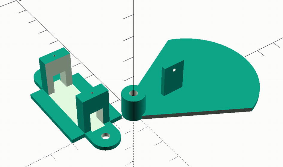
3D printed parts for enclosure (flag, servo mount)
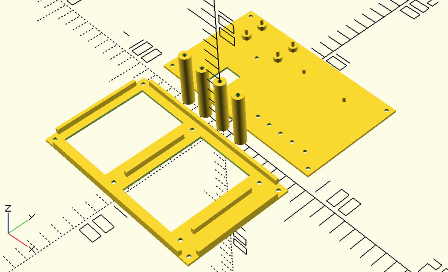
3D printed parts for enclosure (front and back panels, spacers)
Cardboard boxes make excellent prototyping material. They are plentiful, cheap (free), easy to cut, you can write on them, and more. Best of all, if you mess one up, just throw it in the fire and start over with a new one! You could use a cardboard box instead of the 3D printed parts if you’d like. However, you will need to use a double-sided tape to attach the servo mount and servo controller board. Of course, you’ll need to do some experiments with cutting the holes. Hint: See the template overlap for guidance.
Now, let’s see how to assemble the enclosure.
Assembling the Enclosure
The assembly of the enclosure isn’t difficult, but it does require using either a hot glue gun or a 3D printer pen to secure the LEDs, servo mount, and servo controller board.
Front Panel
Mounting the LEDs in the enclosure
The 3D print file is set to create holes for 3mm LEDs. If your printer settings differ or you use larger LEDs, you may need to drill out the holes or open the 3D printer source file in OpenSCAD and change the size of the holes.
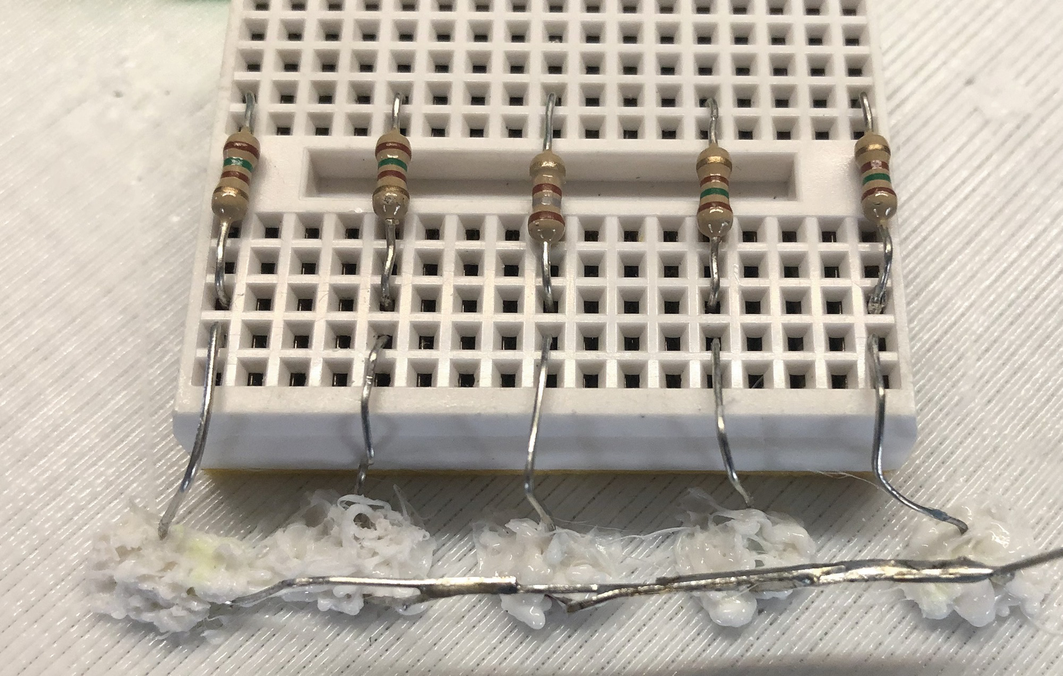
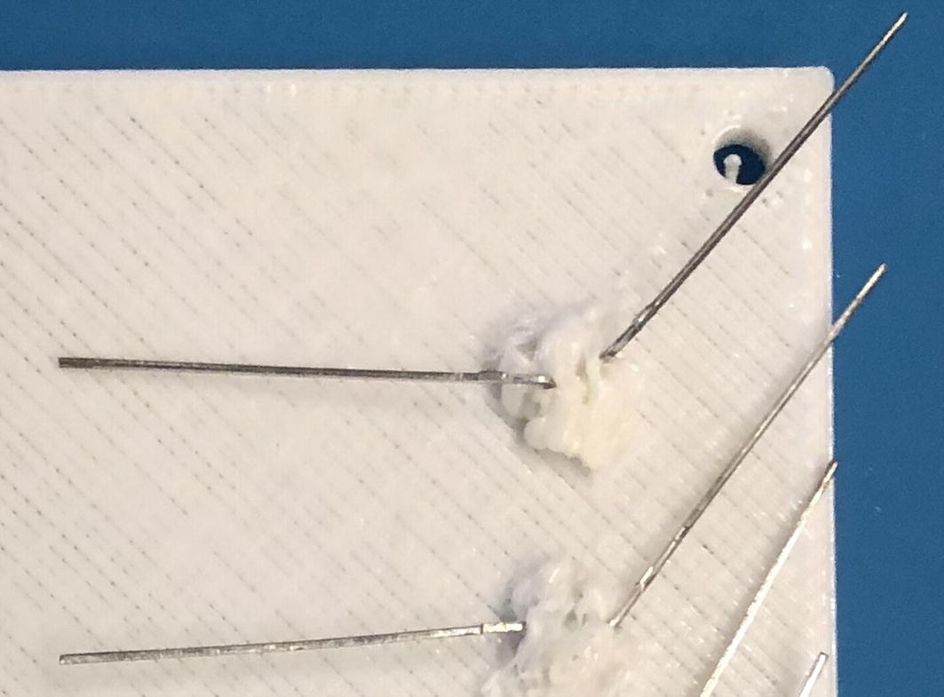
Soldering the LED negative pins

Mounting the servo mount and servo controller
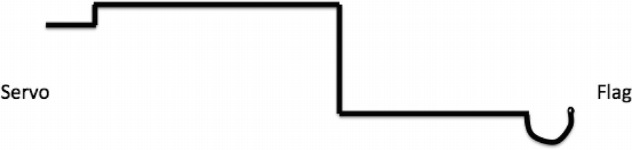
Forming the servo rod/cable

Masking the flag
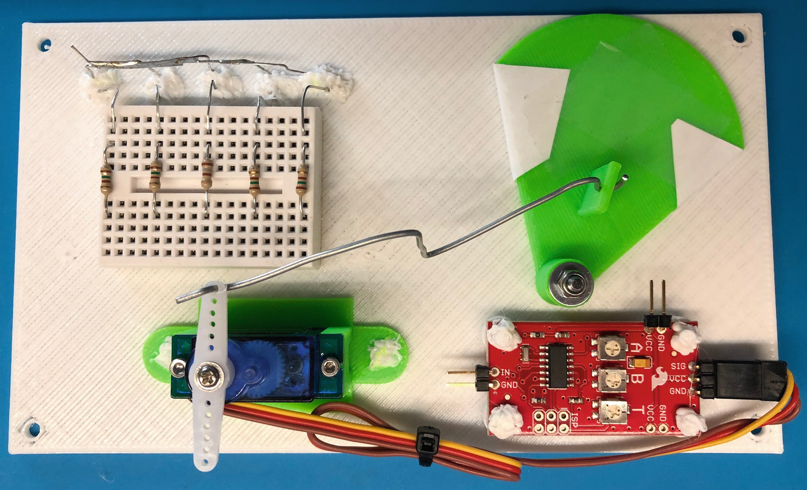
Completed front panel
Never rotate a servo when it is powered on. Also, never connect or disconnect a servo when the circuit is powered on.
Note that we haven’t written anything on the flag yet. We save this until we get the project working. More specifically, we write “IN” on the flag when the flag is in the correct position and the client has sent the correct message. Similarly, we write “OUT” on the flag when the client sets the flag to the out position.
Now, let’s work on the rear panel.
Rear Panel
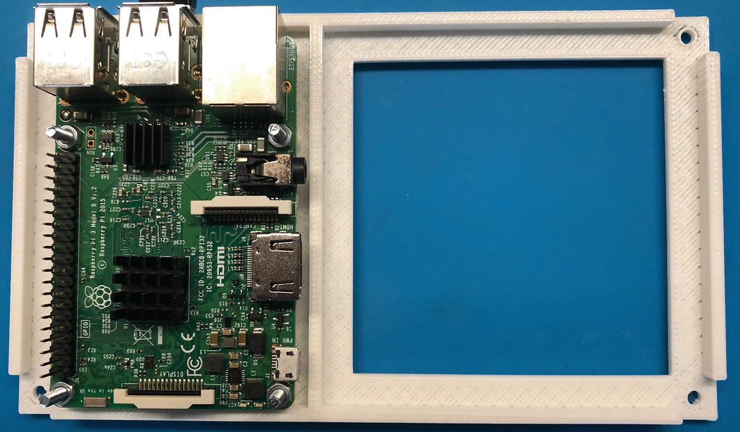
Mounting the Raspberry Pi
Now you can make all of the remaining wiring connections.
Putting It All Together
For this step, lay the front and rear panels face down on a flat surface with the rear panel on the right. Go ahead and place the long M3 screws through the front panel and slide the spacers over them. Use a GPIO map to locate all of the pins from Table 14-2.

Wiring completed
Be sure the Servo Trigger is unobstructed or at least positioned so that you can get to the three potentiometers on the board to tune it should you need to do so.
Be sure to double-check and triple-check your wiring before powering on your device. There are a lot of wires in there, and it is very easy to get things mixed up. Use the tables earlier in the chapter as a guide to trace each and every wire from the Raspberry Pi GPIO pin to the device. For example, ensure that GPIO 20 is connected to the Servo Trigger signal pin.
OK, now you can carefully assemble the panels. Lift the rear panel and place it over the front panel and align the screws. Be careful not to disconnect any of the wires. Secure the panels with M3 lock washers and M3 nuts.

Faceplate template
There’s just one more step to perform. You need to tune the servo so that the flag moves correctly, and it is shown in the window.
Tuning the Servo Trigger
The Servo Trigger has three small potentiometers on the board for adjusting the servo. Use these to change the off and on (triggered) positions of the servo so that your flag clearly shows in the cutout window and that it travels far enough to change from one value to another (from IN to OUT).
Use a small flat blade screwdriver to adjust the potentiometers. The A potentiometer adjusts the off position, and the B potentiometer adjusts the on (triggered) position. If you find this to be the opposite, you can either roll with it that way or simply rotate the entire servo mount 180 degrees.
You may find that you have to experiment a bit to get this right. This is really the hardest part of the prototype and the reason you’re using temporary housing. You may have to adjust the wire that connects the servo arm to the flag shortening or bending it so that the action runs smooth. You may also have to detach and realign the servo arm to get it in the correct location.
Once you get the servo tuned correctly, take a moment to draw a small outline of the cutout on the flag in each position. You can then disassemble the flag and write IN and OUT in those locations.
OK, now you have your components assembled and the servo tuned. Let’s test it out!
Testing the Prototype
OK, so now the real fun begins. Before you power on the device, if you haven’t already done so, write the IN/OUT values on the flag and label the LEDs. I added my own comments here and there.
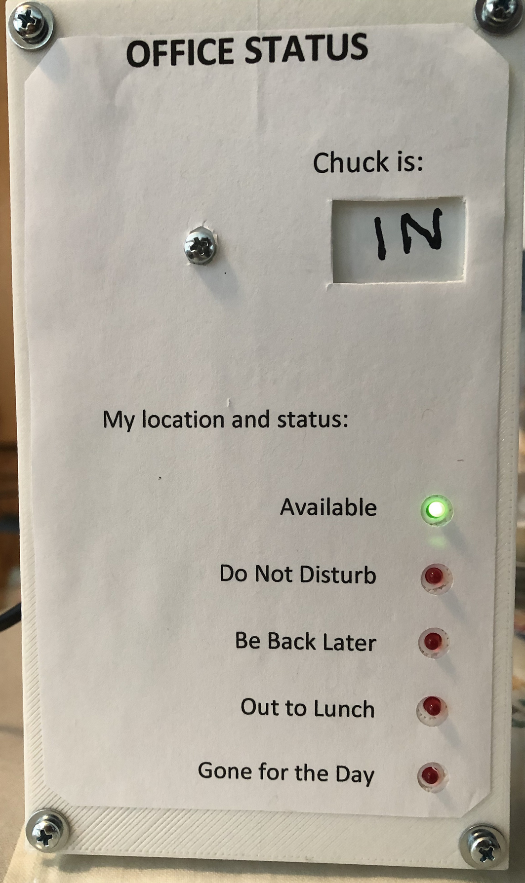
Chuck is in his office!
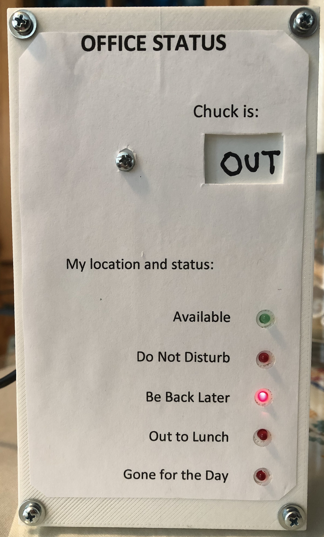
Chuck has left the building…
Now that everything is working, I am sad to say the coolness and jubilation eventually wears off.
Taking It a Step Further
I chose to use 3D printed parts for the enclosure for the project because it is easy to modify and reprint. However, you may want to consider implementing this project using a more robust enclosure. For example, you could purchase a plastic or aluminum enclosure and cut or drill the holes for the LEDS and flag mount. Another possibility is using a small piece of thin plywood to make the bezel and mount it in a deep photo frame or shadow box.
If you like this project and had as much fun as I did building it or better still if you want to take it to work and put it in service, I encourage you to consider taking the project a step further with a better enclosure. See Chapter 17 for ideas on where to publish your work. Be sure to reference this book as the origins of your idea.
Summary
I find those IoT projects (or any project) with mechanical elements really fun to design and implement. Mechanical movements allow you to bring a bit of whimsy and wonder to your projects. My interest in mechanical movements began as a child when I saw the early animatronics displays at Disney World and other amusement parks. Now that you have had a small taste of one method you can use to create such devices, you can begin to think about how to incorporate similar mechanisms in your projects.
In this chapter, you discovered how to build a nifty out-of-office sign with a mechanical flag and LEDs controlled across the network. This represents the fundamental building blocks for other remote controlled IoT projects.
In the next chapter, you explore an exciting new venue for Windows 10 IoT development—a brief introduction to how to take your IoT ideas into the enterprise, commercial realm. Yes, that’s right. You can build consumer, enterprise, and even industrial solutions with Windows 10! How cool is that?