
After learning about going straight and turning, you're now able to give your robot just enough information to get seriously lost on the game field. No matter how well your robot navigates in any direction, it won't take long before it loses track of where it is facing. This is just the nature of LEGO robots; they're never going to be consistently accurate without a little help and some realignment.
When your robot starts running a few missions, you'll notice that after just a few navigation changes, such as going straight, turning 90 degrees, going straight again, and then maybe backing up, it will rarely end up in the exact same place again, much less be pointing in the same direction each time. When you plan your robot's missions, it's always a good idea to build in some expectations of error by about an inch. Doing so will be important when you're thinking through your strategies for completing a mission. But there also ways to use your environment to get your robot pointing in the right direction even after you've left base.
Winning robots will constantly realign themselves throughout the game to ensure consistency for each mission they attempt. The trick is to locate the points on the game field that your robot can align with to get the best results. You're looking for anything that is a constant on the field, things that don't move and remain in the same position relative to the rest of the field at all times. Such things can be markers printed on the game field, such as lines or shapes or the actual walls of the game table itself, which can be very useful when the game mat is lined up properly on the table. Or there could be actual field objects that are affixed to the mat throughout the game and won't be moving or removed.
When you are coming up with your mission strategies, think about things that can help you square up your robot again after just a few moves. Is there a wall close by after you make a 90-degree turn? What about the field mat; is there some kind of line or border that your robot can try to detect and line up with? Maybe the mission object itself has some way for you to use it to square up before or after you've completed the mission. These are all things you want to think about as you do your planning. They will be the keys to having successful and accurate robot runs.
One of the obvious objects to use for aligning your robot is a wall of the game table. Most LEGO robot events will have either walls or field edges that you can use to square up with. In FLL, every game has them; every season they are one of the true constants of FLL games. This is one reason that it is important to have a game table when practicing for an FLL event. I know some schools don't have room for the tables in their classrooms, so teams just lay the field mats on the classroom floor during meetings. While this works well for space conservation in the classroom, it will not prepare your team for the actual game-day competition environment. To be successful in winning an FLL event, you are going to need a practice field that's as close as possible to what you'll be running on at your robot event.
You have already learned that the table walls are our friends because we can use them to help us go straight in wall following, and now you know that they can help us get our robot back on track and facing the right direction. There are multiple ways to line up a robot using the walls: we can include sensors on our robots to detect the walls or use some simple passive techniques.
Let's say your robot has traveled straight, parallel to the table wall, down the game field and made a 90-degree turn. Afterward, you would expect the rear of your robot to be perpendicular to the wall of the table, and if you built a proper robot and followed some of the techniques we talked about in previous chapters, most likely you would correct. But what if there was a ripple in the mat or one of your wheels slipped some when you turned? A number of things could mess up your robot's navigation. How do you guarantee that your robot is pointing in the correct direction?
The easy way would be to simply back up the robot into the wall. If your robot has a nice flat, even back surface, you can simply slowly back up the robot until it meets the wall and then push against the wall until your robot chassis is flush with the wall. This is a passive method because we're not using any kind of sensors to detect the wall; we're simply using some time and pushing up to the wall until we assume we're straight with it. You can see in Figure 6-1 that DemoBot's rear chassis is designed to allow for flush contact with the wall.
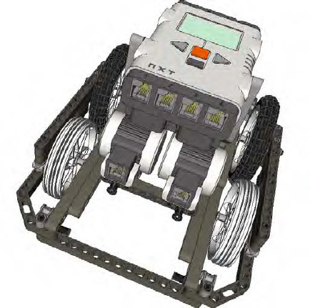
Figure 6.1. DemoBot has a flat rear surface on the chassis to allow for flush contact with the wall when squaring up.
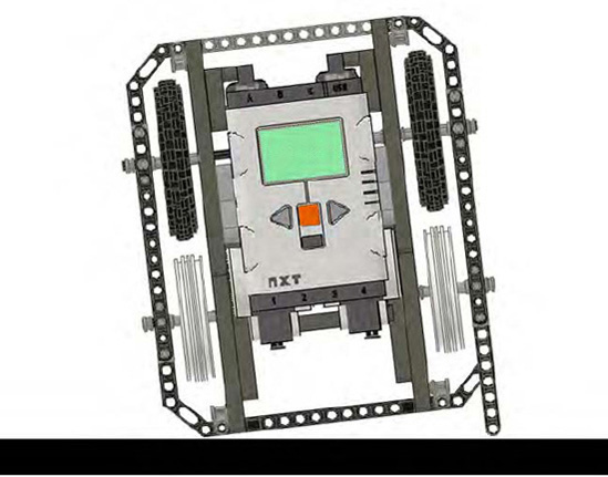
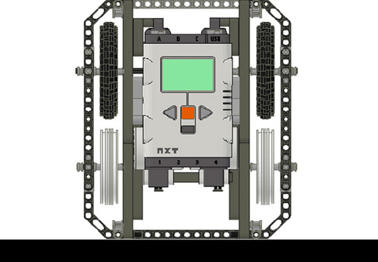
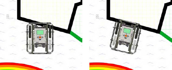
The passive approach only works if your robot chassis is flat on the back. If anything extends beyond the back of the robot, that extension will contact the wall and could cause the robot to wind up in an undesired angle for your next approach. So again, for this approach to work, you need a rear surface or even bumper on the your robot's chassis that is square with your robot's drive system and will allow the robot to become square when pushed flush with a flat surface, such as the table walls. Also, be sure that the contact point on your robot is fairly centered in height relative to your robot's chassis as well. If it is too low or high, you could get unexpected results as the robot pushes against the wall. The goal is to make a nice smooth touch and gently line up the robot. You can see in Figure 6-2 that the robot fails to square up properly, because access to the rear of the robot's chassis is obstructed, but in Figure 6-3, DemoBot has no problem squaring up with the wall.
Code for implementing the passive approach is very simple; a Move block with both drive motors running at the same slow, steady speed toward the walls is all that is needed. Since we are not using any kind of sensors to detect the wall itself, a duration of time can be set for executing the Move block. The actual time used will have to be calculated based on how far the robot is expected to be from the wall at the time. It's a safe bet to give the robot an extra second or two to help a robot that is further off angle than expected. In Figure 6-4, you can see a sample program that aligns the robot with the wall after making a 90-degree turn, and Figure 6-5 shows the path the robot took when running the sample program.
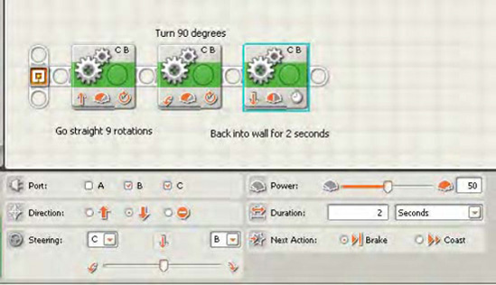
Figure 6.4. The Move block at the end of the program will allow our robot to square up with the wall, giving it 2 seconds to do so.
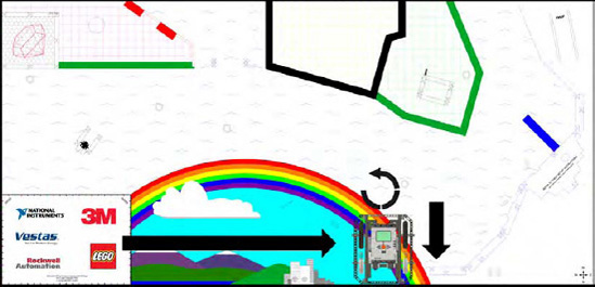
Figure 6.5. The path that the robot follows as it follows the code in Figure 6-4: After making the 90-degree turn, the robot backs up and squares with the wall.
I would avoid using rotation or degrees for your duration, because doing so can cause the robot to get stuck. With passive wall squaring, we're expecting some tire slippage when the robot makes contact with the wall, but if this slippage doesn't occur and we're using rotation or degrees as the duration, the duration value will never be met since the tires are not slipping, thus causing the robot to become stuck. With time as the duration, even if the robot does not spin the tires, the duration value will be met, since time is not dependent on tire spin.
If you desire a little more feed back when aligning your robot with the wall or other field object, Touch Sensors on the rear of your robot can come in handy. The most straight-forward system would be to mount two NXT Touch Sensors on the rear corners of your robot chassis. You will want to keep them spaced at a distance close to the width of your robot to help ensure that the robot is truly lined up square with the wall.
The advantage of receiving feedback when touching the walls is that you remove the guesswork we had with a passive solution. Instead of our program relying on duration of time, it will simply have the robot back up till both touch sensors have triggered a positive response, letting the program know that the robot is aligned and ready for the next statement in the program.
The disadvantages of such an alignment method are that you have used up two sensor ports on your NXT brick and two NXT Touch Sensors. Now, if you can make use of these sensors this configuration for some of your other mission task, using them for squaring up is not a disadvantage at all. For example, you may use the sensors for alignment but also use them to detect when your robot reached a mission object. In Chapter 7, we'll talk about bumpers and Touch Sensors for helping detect such objects.
In Figure 6-6, you can see DemoBot configured with a pair of NXT Touch Sensors on its rear chassis. As the robot backs into the wall for alignment, the Touch Sensors may trigger at separate times depending on the approach angle of the robot. The NXT-G brick will be programmed to continue driving backward slowly until the Pressed condition state of each Touch Sensors is met, as shown in the sample program Figure 6-7.
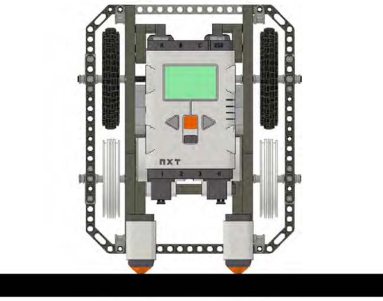
Figure 6.6. DemoBot with dual NXT Touch Sensors installed on the rear of the chassis for interactive wall detection
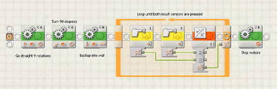
Figure 6.7. An NXT-G program driving the robot into reverse into the wall until both NXT Touch Sensors have been pressed
When using NXT Touch Sensors for alignment, it is very important to put the touch sensors in a location on the robot from which they will make solid contact with the wall or object that you are attempting to detect. One year when judging at the FLL World Festival, I witnessed a team using such a technique for alignment, but it had put the robot's sensors too low. The robot chassis actually flexed some when the robot made contact, preventing one of the two Touch Sensors from ever completely pressing in far enough to detect the wall. This caused the robot to get stuck where it was as it continued to try to drive in reverse while waiting for both sensors to detect the wall.
The sad scenario I've just described could have been avoided in two ways. First, the team could have raised the sensor higher on the robot to move it closer to the actual robot chassis, so the chassis didn't flex as much when making impact. Even some extra bracing would have helped. Second, the team could have added some logic to the robot that said, "Move backward until both Touch Sensors are pressed or until 3 seconds have passed." Adding that second duration condition of time would require a bit fancier programming, but it would have saved the team in competition. In your own designs though, you may prefer to focus on the simplicity of good structural design as a way of avoiding the problem.
Tip
You can implement a similar approach using two NXT Light Sensors located on the rear of your robot chassis facing up toward the wall instead of down at the game mat, and just look for both sensors to be in a state where they no longer read ambient light from the room. However, this approach is not likely going to be the best use of your light sensors. If you really desire feedback when aligning with the wall, use the NXT Touch Sensors. They are better designed for such usage.
Besides the table walls, most game fields will have some type of printing or markings on the field that your robot can use for alignment. You can align with those markings with light sensors, using some of the techniques discussed earlier in Chapter 5. The trick is that you need to use a second NXT Light Sensor for alignment. Only one is included in the LEGO MINDSTORMS kits, but a second one can be purchased for a relatively small cost.
Aligning the robot using field markings can be very effective and can give you a bit more flexibility than solely relying on the table walls. Of course, ideally, your robot will take advantage of both types of squaring—wall and field marking. With the field markings, you will be able to align the robot with various angles depending on the actual markings on the field. For example, in Figure 6-5, which shows the FLL 2008 Climate Connections game field, you can see that different areas have nice thick colored lines outlining them. These lines, if used correctly, where great for helping line up a robot for some of the various missions.
We will use the line as we did the walls for lining up, but instead of being pushing up to the wall, we will need to have some smart code for our NXT to recognize that we are at the line and to determine which direction the robot will need to turn to align itself with the line or marking.
First, we will mount two NXT Light Sensors to the robot and make sure they are parallel with each other and as wide apart as we can get them on our chassis. Having the sensors far part allows our robot to make less-drastic turns when lining up. The closer together the sensors are located, the faster the second sensor will approach the line edge as the robot turns to square up to the line. A greater distance between sensors will allow for a smooth and precise alignment. If this doesn't make sense right now, don't worry; it will once we talk more about the logic involved to turn the robot.
Begin the alignment process by turning on both Light Sensors and searching for the color line that you have been told to expect. For example, say the mission we're going to tackle has a black line in front of it. Well, you know from Chapter 5 that a black line will register a low number reading on our Light Sensor. So our NXT-G code, as shown in Figure 6-8, will tell each light sensor to be on the lookout for a light reading with a low number, maybe 30 or lower depending on if there is any other printing on the field that we need to be concerned with reading by accident. We don't want to trigger a false positive on something that is not our line.
Now, let's say that the robot is running along and the Light Sensor on the right side of our robot detects a black line. Now, we need to find the line with the left Light Sensor. All the robot has to do is stop moving forward and turn to the right until the left Light Sensor also detects the line. Once both Light Sensors have found the edge of the line, the robot should now be aligned with that line.
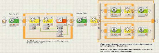
Figure 6.8. NXT-G program aligning the robot with a line detected on the game field using NXT Light sensors
So, what is your robot actually doing? It's using the first Light Sensor that detected the line as a pivot point. Your robot then turns along that pivot point until the other Light Sensor reaches the line, as shown in Figure 6-9. Again, having the light sensors a good distance apart from each other ensures that you get a nice straight alignment with the line. If the sensors are too close together, it leaves much more room for error when making proper alignment.
Knowing that the robot is aligned with the edge of a line or wall can be very powerful in accurate navigation. Good alignment gives the robot a sense of where it's facing on the field. If your robot can make such alignments after every few navigation moves, you will have a robot that can move around the game field with confidence, and you won't have to worry about things such as ripples in the mat, extra tire spin, or even an unexpected field object hitting your robot. Winning robots are self-correcting, and the concept of field alignment is a key part of that.