You're ready to build your robot, but what kind of robot design do you need? You know the rules and the requirements, so now you need a design will best meet your goal of a winning robot. No single design will ensure a winner. The goal is a robot that can deliver consistent results over and over again. And it must be able to perform with the same consistently in different environments. The first part of meeting that goal is to start with a sturdy and effective chassis.
I have found one of the better ways to build a chassis is to start with the drive system and work my way up, this allows room to experiment and see what work design best works. Don't forget to make room for the motors to attach, but you can get a lot done before the first motor is put in place.
Here, we'll cover some design aspects and LEGO elements that can be used in your chassis design. Understanding the principles is important but so is experimenting. Play with the parts in your kit and see how they fit together and interact with each other. You may come up with some variations that someone has never tried before.
Designing your winning robot is going to require balancing size, power, and speed. These three principles are connected with each other; for example, the faster your robot can travel, the less power it will possess. The bigger your robot, the slower it will become, because it will require more power to move. The more power your robot has, the slower it will travel.
You will need to think of your requirements and decide what things are important for your robot. Does it need to be fast? Will it have to push a lot of things and thus need to be strong? Are there lots of small places on the game field that your robot will need to access, thus requiring a small robot? These are the kinds of questions you will need to keep in mind when while you learn about chassis designs.
When building your robot, try to decide how big you want it, but don't think so much about exact size; think more generally. Imagine the desired size as a box; the goal is to keep your robot small enough to fit within that box. With LEGO robots, it is very easy to get carried away with their size. Adding new parts is easy, so things can quickly get out of control.
Remember, even though LEGO parts are relatively lightweight, their weight will add up quickly, and soon, you'll find that you have built something that is going to require a lot of motor power to move around the game field.
When I speak of power, I'm talking about the strength of your robot. Some robots need to push heavy things or even pull some objects. If this is the case, your robot is going to be required to be very strong. Even though we're dealing with LEGO robots, if you gear one correctly, they can produce a great deal of torque, thus giving your robot a lot of power. You do need to be careful, because if you overdo the power, you will break some pieces. I've seen many LEGO gears and axles twisted and snapped from being having too much torque applied.
No one wants a slow robot; we all love build things that go fast. In FLL, you only have 2.5 minutes to complete as many missions as you can, so speed is important. But remember: in gaining speed, the effectiveness of other design principles, such as power and size, will be sacrificed. It's not easy for a big robot to go fast. Also with speed, the risk of mistakes can increase; it's easy for a speedy robot to miss goals. Many times, it's hard for a fast robot to be accurate, so it's a good idea to start out slowly and then increase the speed as you practice your missions.
Even though I didn't list batteries as one of the design aspects, they do have an effect on all three of the principles—size, power, and speed. Obviously, the faster your robot runs, the more battery power it will consume. The same goes with motor power; producing more torque means consuming more battery power as well. These are things you need to keep in mind with your robot design. With LEGO MINDSTORMS robots, you only have a few battery choices, and only two have an effect on the actual size of your robot design.
You can use replaceable or rechargeable AA batteries. If you choose to do this, you will be replacing batteries quite often during practices and competitions. Keep this in mind for your chassis design, and give yourself easy access to the batteries.
Even though the FLL game is only 2.5 minutes long, you will want fresh batteries for each run to ensure consistent performances from your robot. Also, be sure to always use the same type of batteries, running on Alkaline batteries at the beginning of a season and then switching to Lithium batteries will cause big differences in your robot's performance, most likely unexpected and undesired behaviors. So be consistent with your battery choice.
The easiest thing to do for batteries is to use the LEGO MINDSTORMS rechargeable battery pack. This is included with the FLL robot kit and can be purchased separately from LEGO Education as well. Even though the rechargeable battery packed actually runs at a slightly lower voltage than AA batteries, it will produce a more consistent power level for a longer period of time. Remember, consistency is a good thing for LEGO robots.
Be sure to keep the size and location of the recharger port on the battery pack in mind when building your robot. The battery pack will add about a quarter inch to the thickness of your NXT brick, and this could affect the design if you were originally using the changeable AA batteries. The recharger port needs to located in such a way that you can plug in the charger with out having to remove the battery or the NXT from the robot. You'll also want to be able to see the charger indicator lights on the battery pack so that you know you're connected and getting a good charge. Nothing is worse than leaving the robot charging to only find out later that that plug wasn't connected properly and it didn't charge at all.
For your robot to perform consistently, it will need to be properly balanced; all wheels or threads need to keep in contact with the game field at all times to ensure consistency and repeatability during each mission run. A robot that tips over or wobbles will be very hard to control and program for dependable mission attempts. Balance depends on a couple of things: the center of gravity and the wheelbase of the robot. The wheelbase is any area within a region created by drawing lines between each of the wheels on your robot, as shown in Figure 2-1. The area with in this region is the wheelbase of your robot. For your robot to stay balanced, the center of gravity should be inside the wheelbase; the closer to the center of the wheelbase that the center of gravity is located, the more balanced the robot will become.

For a robot to stay balanced and stable, the center of gravity needs to stay within the wheel base area of the robot; otherwise, the robot could lose its balance and tip over.
The center of gravity is the point of the average location of the weight for the robot. This is not the center of your robot, but the point at which the weight is equal above and below and on all sides. There are multiple ways to find the center of gravity of your robot design; the easiest is to simply balance your robot on a fulcrum of some kind. Balancing the robot front to back will find your longitudinal balance plane (see Figure 2-2), and balancing it from side to side will find your lateral balance plane (see Figure 2-3).


The intersection of these two planes will be the line along which your robot's center of gravity is located. You will need to find the vertical balance plane to pinpoint the center of gravity.
To find the vertical balance plane, tilt your robot up on either its front or back and gently try to balance the robot without letting it fall. Once you feel the robot is balanced, line up a ruler with the vertical plane. The place where this plane intersects the longitudinal and the lateral planes will be your center of gravity.
Keep in mind that you need to build your robot in such a way that all your wheels are touching the ground and have equal weight resting on them. When you start adding attachments to your robot, they could change the center of gravity considerably and put your robot off balance again. We will talk more about that in Chapters 8 and 9, but do keep in mind that you may need to add some kind of counterweight or shift your center of gravity to make room for attachments.
Another concern that can affect your robot's balance is inertia. Ever been riding your bike and then slammed on the brakes really hard? How did your body react when the bike stopped? It most likely kept moving forward, in some cases your body, or even the bike, may have been lifted up. When you felt this happening you experienced Newton's first law of motion. This behavior of objects is called inertia, and it effects your robot's balance as well. The formula to calculate inertia is simple; its force equals mass times acceleration (F = ma).
Note
Newton's first law of motion says that an object in motion will stay in motion and an object at rest will stay at rest unless acted on by an unbalanced force.
A robot with a high center of gravity can become unbalanced if it's moving and then stops, turns a corner, or climbs an incline. All of these scenarios can be avoided by locating the center of gravity low on the robot and in the center of the wheelbase. Robots with wide wheelbases are going to handle the effects of inertia much better than robots with small wheelbases.
Your robot is going to need to move, and how fast or powerfully you want it to move may determine how you set the gears on it. The current NXT motors have some built-in gear ratios that make them acceptable for direct drive to your wheels if desired. But if you want something a bit faster, or better yet stronger, adding some drive gears could be the way to go. Gears can also be used to change the direction or axis of the rotation or even to change rotation to a linear movement.
The LEGO MINDSTORMS kit offers an array of different gear types:
Spur
Crown
Bevel
Double bevel
Worm
Pulleys
Knob
The following subsections describe each of these types. You'll learn how each type works and what it is best used for.
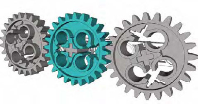
Spur, or straight-cut, gears (see Figure 2-4) are the simplest of gears; they are what most people envision when you talk about gears. When you are simply trying to transfer power from one location to another along a straight line, these are the types of gears that you would most likely use. The teeth are straight and aligned parallel to the axis of motion. To work correctly spur gears must be combined with other gears on parallel axles.
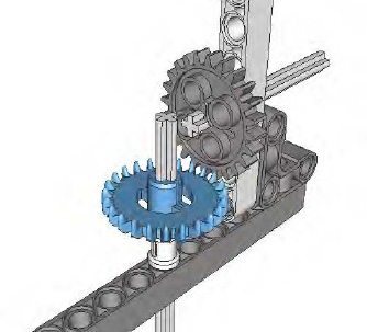
Crown gears (see Figure 2-5) have teeth that are raised on the edges, giving them a crown-like appearance. They are normally used when axles are meeting at a right angle, but they can also be used in the same manner as a spur gear if needed.
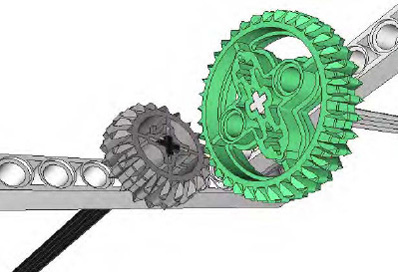
There are two types of bevel gears: straight-tooth and spiral-tooth. LEGO only makes straight-tooth bevel gears (see Figure 2-6). Bevel gears have a slightly conical shape and are useful when axles meet at a right angle in a small space. The bevel gears are much smaller than crown gears and work well in tight situations; they also cause less friction that a crown gear. Angles other than 90 degrees are possible, but using bevel gears at those angles runs the risk of slippage. Also bevel gears, unlike crown gears, can only be used with other bevel gears.

The double bevel gear (see Figure 2-7) is a great mixture between the spur gear and the bevel gear. The double bevel comes in various sizes and allows for a smooth meshing of teeth at various angles. It can be used in parallel and in various angles, and the double bevel can be used with various other gears as well.
In today's NXT robots, double bevel gears are the most popular. Not only are the gears versatile but they tend to mesh together better than the traditional spur gears, giving a smoother motion to your robot and less friction between the gears.
Worm gears are similar to a screw (see Figure 2-8); they have threading that runs along the outside of a cylinder. When meshed with a spur gear at a right angle, the worm gear can create a very high gear ratio. The worm gear will move one rotation for each tooth on the connected spur gear; this is an n:1 (n-to-1) reduction. A worm gear meshed with a 24-tooth gear will produce a 24:1 reduction. Nothing can beat the shear strength and size of a worm/spur gear combination for power, but be careful because the torque can be too much for some LEGO pieces and cause separation or actually break a piece.
It's important to note that the worm gear must be used as the input axle, since the output axle connected to a worm gear cannot turn the input axle. Basically, a worm gear can turn another gear, but another gear cannot turn a worm gear. This one-way relationship can work to your advantage for locking and holding things in place; it might not be so useful in chassis movement but is great for attachments.
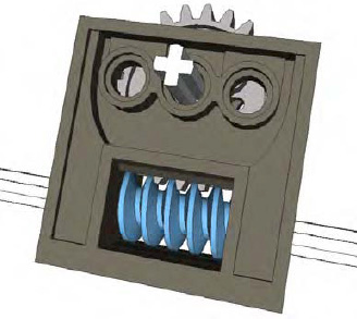
Clutch gears (see Figure 2-9) are special because they are designed to allow the axle to rotate around the gear when the maximum allowable torque is applied to the gear. They contain an internal clutch that will slip and no longer move with the axle once the maximum force is applied. The LEGO 24-tooth clutch gear has "2.5-5 N.cm" printed on the front of it; this is the torque rating for the gear. The clutch gears are useful for saving motors and keeping your robot from breaking or tearing up itself when too much torque is applied to the gear. At this time, LEGO only produces one size of clutch gear.

Pulleys (see Figure 2-10) are unlike gears in that they do not have teeth but have grooves that hold belts in place. LEGO offers a variety of pulley and belt sizes. The ratio of the pulley sizes is similar to the ratios that we get when meshing gears together. Pulleys can be a great choice when trying to deliver power in unusual spaces that gears don't necessarily fit. The drawback of using pulleys is that they will slip when high amount of torque is applied to them, but this behavior can be used to your advantage as an alternative to the clutch gear for creating limited slip mechanisms. Just be careful of relying on pulleys too much in an FLL robot; the belts are not the most dependable for staying in place. You'd hate to have one shoot off during an event.

The knob wheel is an unusual type of gear; it doesn't even look like a gear (see Figure 2-11). But if you look at it closely, you'll realize that it is just a simple four-tooth gear. Similar to the bevel gear, the knob wheel is good for 90-degree, low-speed connections and for applying high torque in angles without the risk of gear slippage.

Knowing all the different gears is great, but how do you connect them together? It's important to understand gear ratios. The gear ratio is how much the output axle turns based on the rotation of the input axle. For example, if you have an eight-tooth gear on your input axle and a 24-tooth gear on your output axle, for every complete rotation of the input axle, the output axle would have turned one-third of the distance. This would produce a 3:1 gear reduction ratio, as in Figure 2-12.
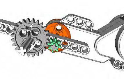
You can read this 3:1 ratio as saying that for every three turns of the input, the output will make one turn. When slowing down the rotation with gears, we call this gearing down or gear reduction, and it can increase the torque generated by the input source, such as a motor.
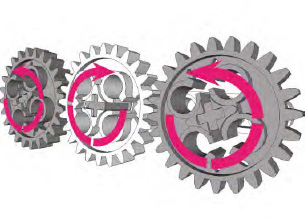
You can reduce the gears more by meshing gears of even higher differences in teeth count, such as combining an eight-tooth gear with a 40-tooth gear to produce a 5:1 reduction. For even greater reductions, you can join pairs of gears together. Two sets of 3:1 gears would produce a 9:1 reduction, as shown in Figure 2-13. You can continue this concept to create extensive gear reduction to produce far more torque than you'd ever need for an FLL robot.

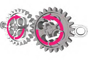
As you can imagine, if you switched the input to the 24-tooth gear and the output to the eight-tooth gear, you would cause the gear ratio to switch as well. The new ratio would be 1:3; for every turn of the input axle, the output axle would turn three times. This is called gearing up and is a way to gain more speed from an input source, such as a motor.
When putting gears together, also note that an even number of gears will reverse the direction of the input, while an odd number of gears will keep the input traveling in the same direction, as shown in Figures 2-14 and 2-15.
One of the most import decisions you will make in regard to your robot design choosing your wheels. Wheels are required to keep your robot stable, to help it handle various terrains, to make it go fast, and to keep it accurate during navigation. With the LEGO MINDSTORMS FLL kit, there are a variety of different tire and wheels to choose from; with the wide variety of wheels available from LEGO, it's hard to know which ones to choose. The larger the diameter of the tire, the faster your robot will travel, but as we talked about previously, a fast robot is not going to be as strong as a robot with smaller tires. So with your design considerations in mind, you will need to carefully think through your needs.
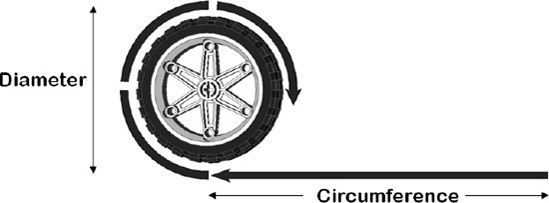
Knowing the circumference of a tire is important when considering which wheels and tires you want on your robot. The circumference will be the distance that your robot will travel after the wheel has made one rotation, or more simply, it's the distance around the circle of your wheel (see Figure 2-16). Knowing this information will be very important when we talk more about navigation in future chapters.
For now, all you have to know is that to calculate the circumference, you simply multiply the diameter of your tire by pi (roughly 3.14), so C = πd. To determine the diameter of your wheel, simply lay the wheel on a ruler and measure the distance across the wheel at the widest outside part.
When mounting wheels to your chassis, it's important to give your axles proper support. If your wheel is mounted close to the chassis, be sure to include a bushing so that the wheel does not get pressed against the chassis. At the same time, you do not want the wheel to be too far from the chassis unless it's supported correctly.
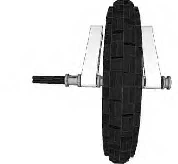
Most robot chassis use a cantilevered assembly to attach the wheels to the chassis. In Figure 2-17, you can see that a single bushing holds the wheel just the right distance to prevent it from rubbing the chassis and is only supporting the axle on one side. This creates friction on the axle as it is being pressed against the chassis. In Figure 2-18, the wheel has been placed further from the chassis with multiple bushings. Because the wheel is further away from the chassis more force is put on the axle and chassis, causing more friction between the two. Also, this setup is going to cause the wheel to camber and give us unpredictable results when trying to navigate. And over time, the axle itself will begin to bend, thus making the robot's performance even more unpredictable.
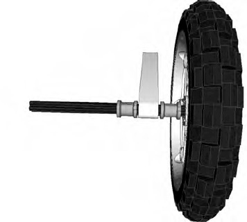

Figure 2.18. Multiple bushing spacing on a wheel axle, moving the wheel further from the chassis causing more friction
The most dependable solution is to have a chassis that fully supports the wheel axle on both ends, giving maximum support the wheel and axle and removing a great deal of friction on the it; see Figure 2-19. We will cover this concept in more details in Chapter 3, and I'll explain the physics behind it. For now, you need to keep in mind that proper support of the axle and wheel are important your chassis design to ensure the reliability of your robot.
When a lot of people think of robots, they don't think of wheeled bots but of ones with treads, like many of the popular movie robots. One pair of treads comes in the LEGO MINDSTORMS kit.
Robots with treads tend to be very low to the ground and have a stable center of gravity; they can also be very agile in small places. Crossing bumpy and uneven ground is easy for them as well.
Even through treads are cool looking and very easy to build, they are not always the best choice for FLL robots. Unfortunately, treads are inaccurate when it comes to navigation. Precision turning is difficult, and even a simple task such as going straight suffers when driving on a flat surface. Treads tend to hop when driving, making accurate navigation on an FLL mat an extra challenge.
There are basically three types of robot chassis: those with wheels, those with treads, and those that walk. Chassis with wheels and treads are the most common in FLL. I've never seen a walker robot compete in FLL; although I'm not saying it can't be done, I'll stick with talking about common wheeled and tread designs.
Also differential steering (or skid steer) is the most common steering design in FLL robots. This is where two motors turning in opposite directions are used to steer the robot. In Chapter, 4 we will talk about steering techniques in greater detail.
One of the simplest designs is the two-wheeled robot design shown in Figure 2-20. This consists of two wheels, each attached to its own motor, with some kind of skids or ball casters to help the robot keep its balance. Depending on the game field, these designs can actually do very well in FLL events. Many times, the simple designs perform the best.
The center of gravity can be a concern with two-wheeled robots just because the wheels tend to be close to the front, and once any attachments are connected, this can cause the robots to fall forward. So it's always a good idea to test and retest the design as you add new features to your robot chassis to ensure that you have not shifted the center of gravity off-center in the wheelbase.

A very common LEGO robot design is the three-wheeled robot, or tribot (see Figure 2-21). The three-wheeled robot is similar to the two-wheeled robot but has a caster wheel instead of skids; the robot will have two wheels, each driven by a separate motor, and a caster wheel in the rear. The passive caster wheel will turn and travel in the direction of the robot. The third wheel is just in place to give balance to the robot chassis and to reduce friction on the game surface caused by skids.
Four-wheeled robots are much more stable that a two- or three-wheeled ones. Having a wheel on all four corners of the chassis provides a large area for the center of gravity, thus making the robot very stable and able to avoid losing its balance. Using differential steering on four-wheel robots is a bit more difficult than with two- or three-wheeled robots, but with proper programming, that issue can be overcome. In Chapter 4, we will talk about this more.
There are two types of four-wheeled robots: two-wheel drive and four-wheel drive.
Two-wheel drive works very similar to other robot designs in the fact that two of the wheels are each driven by single motors; the other two wheels are passive and just tagging along for the ride to add stability for the robot. Steering can be a challenge with two-wheel drive, since one wheel on each side of the robot is going to be skidding while the robot turns. If these wheels have good traction on the mat, they can cause a lot of resistance during the turn. Since these passive wheels are not being powered, they really don't need to have a tire (see Figure 2-22); you can run the wheels without tires to allow them to skid freely on the mat when turning.
A four-wheel drive robot is a bit more work to build; each pair of wheels on the side of the robot needs to be driven by a single motor. In most cases, this is going to require some type of gearing setup. Four-wheel drive is useful when you need to have a strong robot or one that can climb steep inclines. A four-wheel drive robot will steer the same way other differential steering robots do, but instead of having just two turning, two wheels will turn in one direction and two in the other. There will be some skidding by the wheels, but turning all will minimize this. Also, the closer the wheels are to each other, the less resistance they will encounter when turning.

Six-wheeled robot chassis are great when designed correctly. The wheel selection in the LEGO MINDSTORMS FLL kit is a bit limiting for such designs, but if you have access to some of the huge variety of other LEGO wheels, a six-wheeled robot can be done quite nicely. There are really two types of basic design ideas for a six-wheeled robot.
The first design option is very similar to the four-wheeled robot but with an extra set of wheels either in all-wheel-drive mode or still just two-wheel drive. If you need power, six-wheel drive works well but is not always the best choice for FLL challenges. Steering can become a bit challenge as well as navigating tight spaces. So even though using six wheels makes for a cool design, this is often not the best choice.
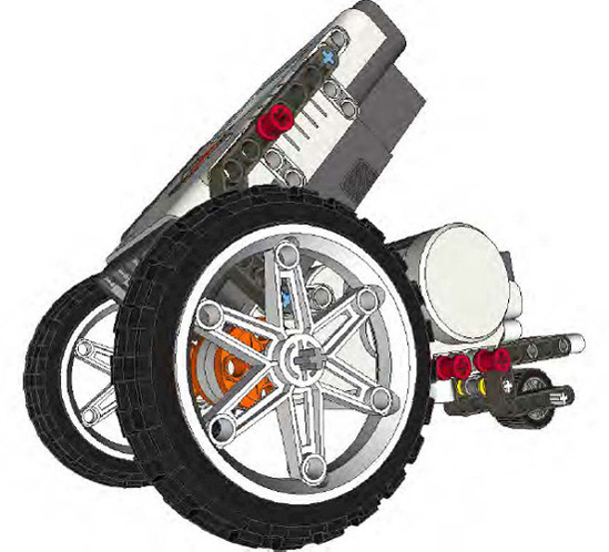
Now, the other six-wheeled design involves middle wheels that are larger or set lower that the wheels on the ends; this is sometimes referred to as a West Coast chassis. The idea is that the center wheels are the drive wheels, so when the robot turns, the balance of the robot will shift as needed to either the front or the rear wheels. However, the amount of friction during the turn is limited, since the balance will fall mainly on the center wheels.
For this design to work properly, your robot chassis needs to be balanced over the two middle drive wheels. When you do this properly, you can have a very nimble robot chassis that can still be of a substantial size, as shown in Figure 2-23.

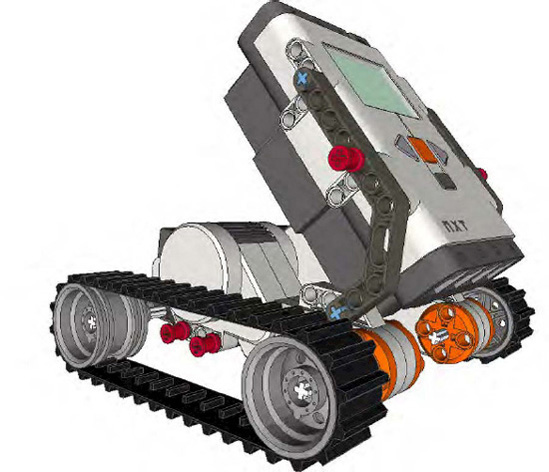
A tracked robot can have a similar wheelbase to a wheeled robot, but of course, it's using a set of LEGO rubber tracks. The tracks give the robot chassis a very stable stance and a naturally low center of gravity (see Figure 2-24).
A tracked robot chassis is very helpful when tackling obstacles that involve crossing over an opening or uneven surfaces. The 2009 Smart Moves challenge featured a dyno-meter that the robots could cross to access part of the field; the spinning nature of the dyno-meter caused many of the wheeled robots great headaches, while the tracked robots tended to do better at making the crossing.
Unfortunately, the drawbacks in using tracks tend to outweigh the advantages. Tracked robot chassis have a hard time traveling in a straight line and tend to hop on a smooth surface. Also, keeping tension on the tracks can prove to be challenging at times. Often, a third wheel inside the tracks will help relieve any issues with tension but will not help the tracks to remain predictable during missions.
I don't want to discourage a team from using tracks on its robot, so try them if you like the idea of using them and they meet the requirements of your mission task. As with everything, experiment and see what works best for your situation.
Once you have completed your chassis, if you find that it seems to be misbehaving and not moving smoothly, there are a few areas you should check. First, make sure all your gears are positioned at the correct distances and not meshing too hard or binding. Sometimes, gears seem to fit together but are causing too much friction because they're meshing too tightly with the other gears. Also, check all your bushings to ensure that none of them are pressing against the chassis too tightly. Wheel rub is another thing to check; if you don't put the correct spacers on the backs of your wheels, the wheels tend to slide some during practice and could rub your chassis and cause friction.
These are LEGO robots, and parts will move around even when you don't want them to. So it's a good idea to give your robot a good looking over before each event to see if anything has come loose or tighten up.
With any building project, having a good foundation is important to success. This is the same for a winning robot design. Before the robot can be expected to perform well, it needs to start out with a good chassis design. Many teams team to rush the design of the robot so that they can begin working on game missions and then later pay the price of having issues and frustrations because of a poor chassis design. Take the time to get the chassis design right.