
A smart robot can detect its surroundings and make decisions based on its findings; a smart robot is a winning robot. One of the ways to make your robot smart is by giving it the ability to receive input from the game field. Using a light sensor on your MINDSTORMS robot is a great place to start when adding some intelligence. I have found that many new teams are intimidated by using sensors other than the rotation sensors built into the NXT servos, but this doesn't need to be the case.
One of the great things about the NXT Light sensor is that it's pretty much a passive sensor from a hardware perspective: you simply put it on your robot facing the direction you wish to use for detection and wire it up, and it is ready for action. With that said, you will need to have a good understanding of how the sensor works and what you'll use it for in order to get the most out of it. Also, being able to develop smart programming code to interrupt the input received from the NXT Light sensor will be important.
First, you need a better understanding of what the NXT Light sensor is and how it works. Then, we can talk about how we can make use of it.
The NXT Light sensor allows your robot to visually analyze its environment, basically giving your robot the gift of sight. It will be able to detect the differences between light and dark, either by detecting the ambient light of its surroundings or by analyzing the color of something in front of the sensor.
The LEGO MINDSTORMS Education NXT Base Set (9797) includes one NXT Light sensor. The retail product LEGO MINDSTORMS 2.0 no longer includes the NXT Light sensor but instead has an NXT Color sensor. The NXT Color Sensor can be used in the same manner as the LEGO Light Sensor so anything in this chapter regarding the Light Sensor also applies to the Color Sensor.
In FLL, you are allowed to use two NXT Light sensors on your robot. One is often enough, but having a second sensor is helpful with some designs. The rules can change each year regarding the rules in FLL so be sure to always refer to the current rule listings each season.
The NXT Light sensor contains an LED and a phototransistor; the phototransistor actually reads the reflected light from the LED or ambient light in the room. The Light sensor ideally is reading from a very narrow field of vision; this field is based on the distance of the sensor from the source. For example, if you were to point the light sensor at the light in your ceiling, you would get a very high-level reading. Now, if you hold a black LEGO brick in between your robot and the ceiling light, the sensor would not recognized the brick simply because the field of vision is too great. However, if you placed the brick on a table and pointed and held the light sensor just a few inches over the brick, it would be able to detect the dark-colored brick. Keep this in mind when placing your Light sensor on your robot's chassis. Don't position your sensor so far away that it cannot distinguish what you want it to.
The NXT Light sensor can read light in two modes: ambient light and reflective light. Ambient light readings are the actual light values in the current room coming from a light source other than the LED on the NXT Light sensor. Reflective light is measuring the light values returned from the lit LED on the NXT Light Sensor.
The Light sensor can be used to measure the ambient light in an area by turning off the "Generate light" option on the NXT-G Light Block in your program.. Leaving that option off will allow the sensor to use the light in the room as the main source for the Light sensor. For example, you may have a program that wants to know what the actual light levels are in the robot's current location. If the robot is sitting in a room with little or no light, the ambient light level would be very low. If the location is well lit, the ambient light level would be high. Using these kinds of reading is rare in an FLL-type event. During most robotic competitions, the robot is trying to detect markings on the game field and not really concerned about the actual room lighting.
We will be using the Light sensor is to read the reflected light levels, which is the intensity that is returned from the surface that the LED light reflects. On our Light sensor block, we will want the "Generate light" option enabled. When properly calibrated, the intensity levels will range from 100 to 0, but when you look at the actual uncalibrated values of the Light sensor, you will see that the range is much smaller, more like 70 to 30. The range is smaller because the Light sensor can read a much wider spectrum of colors than our human eye can see. So the calibration process puts the values into a range that we can find useful. Later, in the "Calibrating the Light Sensor" section, I will describe the process for calibrating the Light sensor.
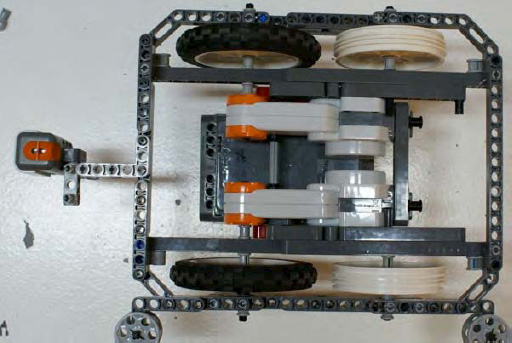
The location of the Light sensor on your robot is very important to how well the robot will respond when doing line following, and a great deal of the location choice it depends on what type of lines you plan on following. If the Light sensor is located close to the pivot point on your robot, as in Figure 5-1, the corrections the robot makes will be very drastic on a sharp curve. When using a differential steering robot, recall that the pivot point is the midway point of the track, and the track is the distance between the two drive wheels. Put the sensor close to this point, and the robot will overshoot a curve more quickly and will be forced to make drastic corrections to get back on track, thus making the robot seem very jerky when traveling a curved path. On the other hand, if the robot will be commonly following straight lines, having the Light sensor close to the pivot point will give a very smooth response.

Of course, the opposite is true for sensors mounted far ahead of the pivot point, as in Figure 5-2. This forward location is ideal when following an arc, because the robot can make corrections quickly and will not need to make drastic turns. But when traveling on a straight line, more zigzag motion will be seen because the line detection is more sensitive with the Light sensor ahead of the pivot point.
Keep the light sensor position and the consequences of its location in mind when analyzing the game field and putting together your strategy for completing the missions. Test frequently and feel free to move the sensor around on your chassis to find what location works best for your design. Do remember that your sensor may need to be recalibrated after each change since its location can have an effect on the light readings.
One of the things you learn quickly with using light as an input source is that it varies from place to place. The light in your classroom or basement can be very different than the light where the robotics event is being held. The idea behind calibration is to adjust your sensor to the conditions expected in the room.
Depending on the room, you may only need to calibrate one time in the room in which you will be running your robot, even if you are running it multiple times within the same day. But if the room has light conditions that may change, such as large windows that allow in natural sunlight, you need to think about how that light will be changing throughout the day. You may want to calibrate your NXT Light sensors before every run. Proper shielding of your light sensors is important for getting consistent light sensor readings as well; we will talk more about that in later sections.
Don't start calibrating your sensor until you have them located where you want them on your robot's chassis, because changing its location on the chassis can affect the values read by the sensor. Ideally, you're going to want to keep your NXT Light sensor close to the game field; 2–3 centimeters is a safe distance, but makes sure your robot can clear any obstacles that it may have to climb. You don't want your robot getting caught on the sensor because of low ground clearance. I've even seen robots that raise light sensors when more clearance was needed and then lower the sensors when a light reading is needed. Such design is maybe is a bit of over-engineering for an FLL robot, but they are fun to watch.
Now, we need to calibrate our sensor so that we can set the real-world values for light and dark. In an ideal environment, the NXT believes white to be maximum light value returned and black to be the minimum value return. These values are represented in the NXT-G code as values between 0 and 100 but rarely will an uncalibrated sensor return either of these two endpoint values. Most of the time, the real values will come back within a range of 30–70.
By calibrating the NXT sensor, we are resetting the limits of the light reading range based on light readings in the current environment. Also, calibrating the light sensor allows the robot to run in different environments without having to actually change the program code to recognize the new room light values.
Note
One year an FLL qualifier was held in an airplane hanger. The location was great, but the lighting was horrible for robots, because every game table in the room had different lighting contrast. This was an excellent opportunity to have a robot that would calibrate its light on each run, and it was too bad our team didn't have such a calibration plan at the time. We did get lucky with a very good run on a table with some consistent lighting; our other runs of the day were not as impressive.
We can perform the calibration in two ways: using NXT-G's own Calibration block that stores the calibrated values in the NXT's memory or by creating our own calibration program that will store the values locally in a file on the NXT brick.
In the NXT-G Advanced tool menu, there is a Calibration block, which is used to calibrate the maximum and minimum levels for both the NXT Light and Sound sensors. The values read by the Calibration block are stored on the NXT brick and remain there until they are deleted or the sensors are recalibrated, even if the NXT brick has been turned off.
Note
If you are using two NXT Light sensors on your robot, the calibration values stored by the Calibration block will be applied to both sensors; the NXT brick does not store separate values for each sensor.
To use the Calibration block, you simply add it to your NXT-G program. Most likely, you would add it in either a separate calibration program or at the beginning of the program you are about to run. If you wish to include calibration in all of your programs and calibrate before each run, creating a My Block with your calibration code would be a good idea.
For example, you could create a My Calibration block; within this block, you would include two Calibration blocks, one to read the minimum light value and one to read the maximum light value. Between the two Calibration blocks, you would write a trigger event such as a Wait block. In the example presented in Figure 5-3, the first Calibration block will read the maximum light value and then wait for the NXT orange button to be pressed before it reads the minimum light value.
The logic for the program shown in Figure 5-3 is as follows:
Hold the robot's light sensor over a light area of the field (on a white or very light color), as shown in the left-hand side of Figure 5-4.
Press the orange button on the top of the NXT brick.
Hear the confirmation tone.
Move the robot's light sensor to a dark area of the field (the darker the better), as shown in the right-hand side of Figure 5-4.
Press the orange button on the top of the NXT brick.
Hear a confirmation tone.
Now, you might want to elaborate on the program. For example, you could add some display prompts to let the user know where to placing the robot's Light sensor and what to do next.

Also, if you attach your NXT brick to your computer via the USB cable or Bluetooth and then select Calibrate Sensors from the Tools menu in the NXT programming software, you will be prompted with a dialog box that will allow you to download an NXT-G calibration program to your NXT. That program will work very similar to the one I've just described and will already have all the prompts in place for easy use.

For various reasons, you may not wish to use the Calibration block that comes with NXT-G. For example, perhaps your robot has two light sensors, and you wish to store a separate calibration value for each sensor. The solution is to calibrate from values that you store in a file. You can apply separate calibration values to each sensor by creating your own calibration program and then storing the resulting values in a text file on the NXT brick. You will be able to read that file each time your other programs are run and retrieve the stored light calibration values.
The processing of storing and retrieving from a local file is really not as complicated as it sounds and can be made into really nice program with not too much effort or code. In Figure 5-5, you can see that, instead of using the Calibration block, the code invokes a Light sensor block that copies a value from the Intensity value of the Light Block into a text file. If you are using multiple Light sensors, you could do this same process for each sensor thus allowing you to have a unique light range for each (again, when using the NXT-G Calibration block, the value calibrated is applied to all Light sensors connected to the NXT brick).

To use the values that you saved, your line-following program first reads the saved values from the files and then calculates the desired light value range. That calculation requires a bit more math for a conditional line-following program but fits right into the proportional line follower that I discuss later, in the section on "Line Following."
One thing that has confuses people about calibration is the process of seeing the newly calibrated values. The NXT brick has a built-in utility to allow you to view the values of its various sensors, but it always displays the uncalibrated values from the Light sensor. So if you use the Calibration block and store new calibration values for the NXT Light sensor in the NXT brick's memory and then use the built-in light sensor viewer, you'll find that it will not show you the newly calibrated values, because it continues to display the original uncalibrated values.
To see the real values, we can write our own Light sensor value viewer that will show us the calibrated values being returned from our light sensor. It's important to know these values so that when we start writing our line-following routines, we know the proper range values our robot will be attempting to detect.
The program is simple, as shown in Figure 5-6. We create a loop that contains a Light Sensor block and is wired to a Number to Text block. The loop will convert the numeric value returned from our Light sensor to text so that we can display it on our NXT screen. The converted value is now passed to the Display block. Then, we wait a second and take another reading of the light sensor.
A program like the one shown in Figure 5-6 will be very helpful in figuring out the initial range for your line-following program, when you're debugging your program, and when you're simply experimenting with different Light sensor positions on your robot chassis. For example, you can move the Light sensor around and get a feel for the difference in light readings based on things such as distance from the game field or even various light sources in your room.
I find it helpful to have such a viewing program running and then shine various light sources at my robot as it sits still on the game field to see what kind of lights have an effect on the reading. Try the lights at various angles too, because many times shadows cause more issues that the light itself.

The NXT-G Calibration block also has a delete function that will clear out any calibrations currently stored in the NXT brick's memory. It could be helpful to clear out such values at the beginning of your calibration process just so you know you're working with clean values in your NXT brick, especially if you're in a classroom where different people are sharing an NXT brick.
Figure 5-7 shows a basic Calibration deletion program. First, the program waits for the user to press the orange NXT button and then it deletes the current calibration via the Calibration block. Finally, it plays a confirmation tone.

Although calibration of your light sensors is important, shielding the light sensors is just as important if not more. The NXT Light sensor produces its own source of light via the LED, so outside light is really just a nuisance. Many robots that depend on light sensors for navigation work best in a dark room, where the only reflected light they are reading is from the LED on the sensor.
I had one coach tell me that his team's robot had perfect light sensor programming, because it worked just as well with the lights turned off. I hated to tell him that the true test is not removing light sources but adding them. And it's not so much the extra light that will get you as the shadows cast by the lights.
One year, I held a scrimmage match at my home for a few teams, and we quickly realized that my basement wasn't going to be big enough to hold the game tables and the teams, so we moved everything outdoors onto the driveway—in the direct sun light! The shadows cast by the sun as it went behind the trees caused the robots to completely lose control. They were constantly reading shadows as black lines and missing their marks, causing them to make some spectacular crashes on the game field. That scrimmage turned out to be more helpful that we expected, since it showed everyone how sensitive their robots were to the extra lighting. After that day, the teams learned to better shield their light sensors from outside light sources.
The first thing to do is keep the light sensor low and perpendicular to the game field; having the sensor at an angle will not give you the results you desire. Around 3 centimeters off the game field is a good distance. Don't get so close that the sensor can't detect the light, but at the same time, don't get so far away that outside sources have an effect on your readings.
If you can build some kind of cover for your light sensors, this is great for preventing distribution from outside light as well. Many teams will mount the sensors under the bulk of the robot chassis to use the actual robot frame itself to block out the room light. Figure 5-8 shows a robot built with shielding around the light sensors.

In Chapter 3, we talked about going straight and having a well-tuned robot. I mentioned using the field environment for help in traveling a straight line, such as running along the wall of the field with wall followers. Well, another great way to navigate along the field is to follow any lines that may be present on the field map. For example, the FLL 2009 Smart Move field was a line follower's dream. There were nice thick black lines that could guide a robot to most of the important places on the field. In fact, those lines were placed specifically to encourage teams to incorporate line following, or at least line detection, in their robot's logic.
I believe a lot of teams recognize that line following is useful but struggle with how to build and develop a good line-following robot. The code doesn't have to be scary. Yes, you can have some very complicated line-following logic and use lots of fancy algorithms to keep your robot traveling smoothly, but there are simple solutions as well. I will try to explain some of the different techniques available. Remember, though, that these are just examples. I encourage your team to use these as a starting point and build on them; see how much better you can make them.
The simplest of line following programs will be a dual-state program, where the light sensor either sees black or white and adjusts accordingly. The robot is not actually trying to follow the line but is trying to find the edge of it. You just need to decide if you wish to follow the left or the right edge of the line. The robot will oscillate back and forth over the line constantly checking for either black or white values; even if the line is straight, the robot will continue to move back and forth searching for the line. The robot is basically looking for two conditions: a light value that is dark or bright. Based on these values, the robot will either go to the right or the left. In other words, the robot is really working in a mode where it has only two conditions (dark or bright) and two actions (turn left or turn right).
This kind of program is a good start for teams just learning about line following and trying to get a grasp on what is going on with the robot and the code. Most advanced teams will use something a bit more complex or at least smoother running. The more the robot oscillates, the slower it will perform. The goal is to follow the line as straight and as fast as possible.
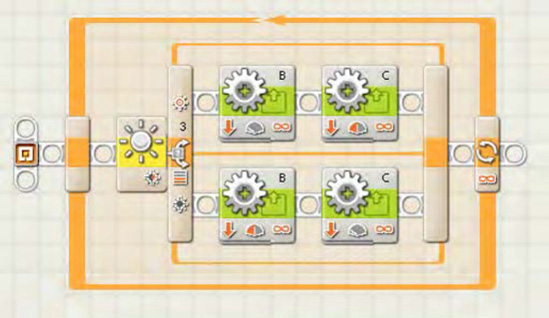
The code for such logic is fairly simple, as shown in Figure 5-9. We're going to assume that our robot is only using one NXT Light sensor at this point. This example will have a master loop that runs continuously. In a real-world situation, you would need to include some kind of condition that would break the robot out of this loop, but for this example, having the robot stay in a constant line following mode is fine.
We will have a Switch block that uses a Control type of sensor, and the Sensor will be our Light sensor. You will need to also configure what port the Light sensor is connected to on your robot; on DemoBot, the light sensor is connected to port 3.
We are going to assume that the robot's light sensor has been calibrated at this point, so our Compare value for the Switch block is going to use 50 as the middle point. If the light value returned is less than 50 (dark), we will turn the robot to the left looking for a value is greater than 50 (light). You can see that the power settings on the various Motor blocks differ depending on what direction we wish to turn, as we talked about in Chapter 4. Next, we'll loop back and check the Light sensor value again. Again, there is no condition in this loop that will allow our robot to go straight; it will always be going to the left or the right.
You will notice that this program is not following the line itself so much as the left edge of the line. If your line has lots of arcs to the right, you might want to switch up the program and follow the right edge of the line instead, since any sudden changes in the direction of the line could cause this simple program to miss the line and send your robot out to Neverland. This type of program works best with lines that stay relatively straight or only curve slightly.
In the dual-state example, the program only had two conditions to deal with: a light value either greater or less than 50. The problem with that approach is that the robot will tend to overcompensate for changes in the light value. Think of a car traveling down the road and one tire starts to go off the roadway. Turning the car's steering wheel drastically to the left will bring the car back onto the road but could very well cause the car to lose control and run off the other side of the road. Instead, the driver will gradually turn the car back toward the road and remain in control of the car, since the compensative reaction is in relation to the amount of error that needed to be corrected. We can do the same thing with our LEGO robots by adding more conditions to our switch logic.
Think about the value returned from a calibrated light sensor; it will be between 0 and 100. If the value is close to 0, we are going to want to make a more drastic change in our direction compared to a value around 35, where we'd need only a slight correction in direction. What we do is divide our possible light range (0–100) into smaller sections. Let's create a series of five smaller ranges (numbered 0–4) by dividing 100 by 20; this will give us new condition values that we will use in our Switch block. I refer to this method as the complex condition method. Table 5-1 shows what code we will put for each condition in our code.
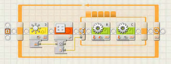
Our example code, shown in Figure 5-10, will again contain a master loop that runs continuously with a Light sensor block. The Intensity value from the Light sensor block will be wired to a Math block, where we will divide the intensity value by 20 and round it off to the closest value. This value will be what we pass to the Switch block. Since it is possible to get a return value of 5 when the light value is higher than 90, we simply just set our condition 4 as the default condition on our Switch block, thus forcing condition 5 to implement the same actions as condition 4.
Within each condition of the Switch block, the Move blocks are set at various power levels to force the robot to turn in one direction or the other, but when the condition value is 2, both Motor blocks are set to the same power level to allow the robot to travel straight.
If you want to make line following, especially of curved lines, even smoother, you could take the complex state method and break down the light sensor Intensity value even more. For example, you could go from five conditional states to ten. Eventually though, you'll have more conditions that you'll want to manage in NXT-G; large Switch blocks can become very clumsy to deal with them in the NXT-G interface. One solution is to implement a proportional algorithm.
Whenever you start talking to anyone about robotics and line following, the term "PID" will come up; it stands for proportional, integral, and derivative. But most LEGO NXT-G programs that people claim are PID really are just "P." For NXT-G, a proportional type of program is very doable, while a full PID program is a bit much to for such a simple programming language (but I'm sure someone, somewhere, has implemented the PID approach in NXT-G).
A proportional system uses a bit of math to calculate the amount of correction that is needed to get the robot back on the line that it is following. Instead of using a set value to correct the direction of the robot, we actually calculate the direction change based on the value read by the light sensor. If the error value is small, the robot corrects very slightly, whereas a larger value results in a stronger correction.
We'll begin our example of a proportional NXT-G by creating the Variable blocks described in Table 5-2.
Table 5.2. Variable Definitions Used in the Proportional Line Following Program
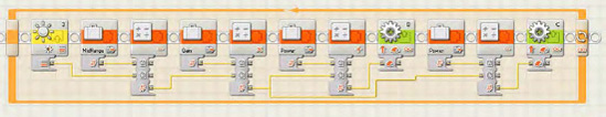
Now, the logic in our code is fairly simple, as shown in Figure 5-11. We first calculate our Error value by subtracting the MidRange value from the Intensity value returned from the Light sensor. Next, we calculate the Correction value by multiplying the calculated Error by Gain. The Correction value will be applied to our Power value and then passed to the Motor block. The trick is to invert the value between the two motors, so for Motor block B, we will add the Correction to the Power, and for Motor block C, we will subtract the Correction from the Power. You can see in Figure 5-11 this logic put into a NXT-G program. Remember that different robot designs will require some adjustments to the Power, Gain, and MidRange depending on your robot's response.
The examples so far have all dealt with robots using a single light sensor to detect the edge of the line you were following. But what if you added a second light sensor and straddled the line? The FLL rules do allow for two Light sensors, even though none of the LEGO MINDSTORMS kits include a second sensor (you can purchase a second sensor separately if desired).
When you have two Light sensors, you are going to want them to be spaced on your robot just a bit wider than the line you will be trying to follow. Set them too close together and you'll never get a valid state for going straight; too far apart and you will find your robot over compensating for direction changes when it hits the line. Ideally, neither sensor will see the line when the robot is centered over the line; they should only see the area next to the line. In Figure 5-13, you can see the DemoBot with two light sensors installed.
If we wanted to use the complex state method we talked about previously, we simply add a second Switch block, so there's one for each Light sensor, and each Switch block would now only have three conditions as shown in Table 5-3.
Table 5.3. Complex State Conditions for Robots with Dual Light Sensors
Light Sensor | Range Value | Action |
|---|---|---|
Left | 0 | Turn sharply to the left; slow down motor B. |
Left | 1 | Turn slightly to the left; slow down motor B slightly. |
Right and Left | 2 | Stay straight; keep both motors equal. |
Right | 1 | Turn slightly to the right; slow down motor C slightly. |
Right | 0 | Turn sharply to the right, slow down motor C. |
Both Light sensors need to start off straddling the line. If the robot gets into a position in which both light sensors see black, the robot will simply slow down. That's because the conditional switches would slow down both motors, and thus try to force the robot to turn in both directions at once. This can happen when a robot leaves base expecting a line to follow just outside of base and it detects the border around the base. To remedy this, either a delay needs to be added to the program when leaving base to prevent line detection, or you just allow the robot to slow down when it first detects the border then speed up again after it is past the border. Figure 5-12 shows and example of how you could write dual Light sensor logic in NXT-G.


The lines on a game field can serve other uses for navigation besides line following. Various areas on a game field often are outlined by a line of some sort. The outline might not even be a true line, just a shape or an image of some sort. These graphics are still important and can be very helpful when trying to determine if a robot is in the right location. Also, be aware that these lines might not simple black lines; many times, they will be colored lines and requite a bit more effort to detect properly with a NXT Light sensor.
In the game field for FLL 2008 Climate Connections (see Figure 5-14), parts of the field were outlined with various colored lines. These were very useful when trying to navigate to a given area to perform a task. What made them tricky to use was the fact that they were colored lines. Also, you had to cross over a large rainbow printed on the mat. The solution wasn't as simple as driving forward until encountering, say, a red line. You had to time when your robot would begin looking at the correct red line and move past the rainbow, or you had to count how many red lines you encountered.
Let's talk about finding lines in general. Then we'll look at how color lines appear to an NXT Light sensor.
If you take a look at the 2008 FLL Climate Connections field mat shown in Figure 5-14, you will see that it doesn't have a lot of lines that would be helpful for line following. However, there are lots of thick lines that either outline or could guide a robot to a particular location on the field. These lines aren't there just for looking pretty. They are there for you to use to help your robot navigate to particular locations. In the middle of the field, you will see a lot of open space, and it would be very easy for your robot to get lost in this space. Having the borders enables you to better program your robot to detect when it has reached a location that you are targeting.
Say, for example, your robot leaves base and is heading to the location I've marked as "Zone A". After the robot leaves base, it will be very dependent on odometry to find its way across the field. During this time, it should start looking for the thick black border around Zone A using its Light sensor. You will have to be careful that the other colors on the field don't confuse your robot. In real life, that rainbow at the bottom of Figure 5-14 tripped up many robots. You need to think, when planning the task for your missions, about what things can be in your way. What other markings on the mat can confuse your robot?

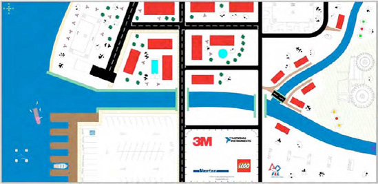
Now, look at the FLL 2007 Power Puzzle field mat in Figure 5-15; it was very different from the 2008 Climate Connections mat in that it had much better defined zones with easy-to-track borders. There were a few roads that you could use for line following. Plus, the blue rivers were great for breaking up the different areas of the mat, giving your robot quick feedback for where it was located currently on the field. Notice the three obvious black lines down the middle of the mat crossing the robot's path as it leaves base heading north. Counting these lines is a great way to help the robot learn where it is located.
Now, when you count lines, remember that you cannot just count how many times your light sensor sees a black line, because as a light sensor travels over a line, it will read it multiple times. You will have to include edge-detection logic in your code, along the following lines:
Look for a black line, or rather a black reading.
Increment a counter when black is encountered.
Begin looking for a transition to white, (i.e., for a white reading).
Go back to step 1 when white is encountered.
Once you find white, start looking for black again; this process would continue for however many lines you're expecting to encounter. In Figure 5-16, you can see an example of what such code would look like in NXT-G.

In this NXT-G line-counter code, the robot runs forward and waits for the Light sensor block to detect a black line. Then, the next Light sensor block will wait to find the next nonwhite area, letting us know that we have completely crossed the black line. When the loop counter reaches three, this Loop block exit and the Move block at the end will stop the robot.
You will notice that, on the field mats in Figures 5-14 and 5-15, many of the lines or areas are not simple black-and-white lines; actually, many of them are colored lines or edges. Even though we're using the NXT Light sensor and not the NXT Color sensor, we can still detect different colors. We do so by interpreting the different colors as shades of grey. The values returned for a given color will fall somewhere in the spectrum between 0 for white and 100 for black.
Ideally, you will still be able to calibrate your Light sensor on a white-and-black source, and the color values will fall between the calibrated range of 0–100. It is best to first calibrate your Light sensor, and then by using the light value view program place your light sensor over the various colors on the game field map and use the light value view program to read and record the values for each color. As long as you can calibrate your robot consistently the color values should be read the same.
Be careful! Some colors will share the same value. For example, many times red, green, and gray will return the same intensity values to the NXT Light sensor. This is why it is important to get a good reading on each color and keep track of which values register the most consistent results.
Also, when you are thinking through your strategies for navigating a game field, look for colors that contrast more drastically with other colors to help avoid confusion and make finding the navigation points easier. Thick lines are, of course, going to make better markers than thin or fussy lines and edges. You are really looking for anything unique that can produce consistent readings back to your program. Consistent markings are going to produce consistent results.
Light Sensors are one of the most helpful sensors when trying to navigate most robotics game fields. In FLL the game field maps are full of clues that can be utilized by Light Sensors. Many teams will shy away from using them just because they have a bit of a learning curve when first using them. But almost all winning teams take advantage of Light Sensors when navigating the field....