CHAPTER 10
WBS Examples and Descriptions
This chapter includes examples of different types of work breakdown structures (WBSs) that are analyzed to illustrate how the principles presented in this book apply universally. They complement the examples covered in earlier chapters and include a brief analysis of key features.
The examples include the following projects:
1. Implementation of Enterprise Resource Planning—Version 1
2. Implementation of Enterprise Resource Planning—Version 2
3. Book-Writing Project
4. Dinner Party Project
5. Museum Project—Project Definition Phase
6. WBS for a Planning Phase
7. WBS for a Major Department of Energy Program
8. Information Technology Program
9. NASA Standard Base Maintenance Service Contract
11. The Rural Meat Company, Enterprise Resource Planning (ERP) Implementation—Class Project
12. Roaming to Win Project at National Wireless, Inc.—Class Project
Excluded from this list are WBSs for large DoD projects that fit one of the eight templates included in MIL-HDBK-881A. Figure 8-1 in Chapter 8,however, presents a typical WBS of this category.
There are also many examples scattered throughout the book, such as Figure 6-2, Generic Consumer Life Cycle Program, that provide insights and templates for WBSs.
1. IMPLEMENTATION OF ENTERPRISE RESOURCE PLANNING—VERSION 1
Figure 10-1 is an example of a WBS that represents the work required to implement an ERP program.
FIGURE 10-1 ERP Implementation Project

Figure 10-1 is an example of a results-type WBS, where there are a standard set of phases or stages—from Analysis through Cutover—that the program team progresses through to achieve the result of a successful implementation of ERP. Actually, this WBS is sufficiently general to be used for any software project with a prototyping phase.
2. IMPLEMENTATION OF ENTERPRISE RESOURCE PLANNING—VERSION 2
On his website, Richard Byrom provides a template (see Figure 10-2) prepared in Microsoft Project that he states “should provide any parties interested in implementing Oracle applications with a framework for doing so. It contains the detailed tasks involved and lists the associated resources that may be needed.”1 The WBS codes tie back into the Oracle AIM documents that should be prepared for each task and phase. This WBS was derived from the suggested Microsoft Project file using WBS Chart Pro. Note the unique WBS numbering used in Figure 10-2.
FIGURE 10-2 Oracle ERP Implementation

Figure 10-2 also is the WBS for a results-type project, and the work progresses by phase from the Definition phase through Production. An overall Project Management WBS element is missing, but Byrom has incorporated equivalent Project Management WBS elements in each phase as a Planning WBS element. The author would have kept “Project Management” separate as a cross-cutting item at Level 2, with the phantom WBS element “ERP Implementation Program” at Level 1.
3. BOOK-WRITING PROJECT
Writing a book or preparing a report where research is required is a common activity. There is a tendency to identify the research or the writing as the primary output, when the primary product is the actual published book. The sample in Figure 10-3 is included to provide more detail than was included in the Book Project WBS shown earlier in Figure 2-18.
FIGURE 10-3 Sample Book Writing Project

The Research element is both an analytical element and a process element. The Writing element is a process element representing the writing phase of the project. After the writing is complete and the chapters are edited, the next and final phase of publishing the book proceeds. Note that the Level 2 Research element generally covers the work that applies to the book as a whole, and that the Research work packages at Level 4 relate to chapter-specific research.
4. DINNER PARTY PROJECT
The dinner party project in Figure 10-4 is a service-type project. “Project Management” is the only cross-cutting element at Level 2, which is typical for this category of project. This WBS was initially prepared from the bottom up by first listing all the activities, as shown, and then grouping them into the logical categories, as shown at Level 2.
FIGURE 10-4 Bottom-Up WBS for a Dinner Party

This WBS contains work elements at Level 1 and Level 2, and activities at Level 3. Note that “Food and Drink” could be separated at Level 3 and the activities under each would be at Level 4. Similarly, the “House Preparation” category could be separated into work areas related to “Cleaning” and the “Dinner Environment.” There is no logic in the order of the activities listed under each WBS element.
A top-down WBS would have been structured as shown in Figure 10-5, where the initial focus would be on the objectives and outputs. The primary output is the actual dinner, and other outputs are the invitation activities and house preparation. In any event, the WBS elements, except for “Project Management,” are service elements and represent the logical grouping of activities to facilitate planning.
FIGURE 10-5 Top-Down WBS for a Dinner Party

A WBS for a service project, where there is not a tangible product, does not usually have any cross-cutting elements other than “Project Management.” The reason is that there is usually a main event, like the dinner itself, but there is no inherent physical structure to the elements, only a logical grouping. The other elements are also convenient and logical categories of work that complement the main event. The 100 percent rule applies, but it is more difficult to determine if all the work is represented at each level.
5. MUSEUM PROJECT—PROJECT DEFINITION PHASE
Figure 10-6 is the WBS for the project definition phase of the Museum Exhibit Program outlined in Figures 6-5, 6-8, and 6-9. This WBS was developed as a team effort of the organization responsible for exhibit programs and was designed to be a template for future projects. Each phase in the program was planned as an independent project, and each phase has its own WBS.
The Project Definition phase of the project life cycle begins when the Idea Statement is approved and the go-ahead is received to define the project. The primary output of this project is an approved Statement of Purpose, with supporting documents. Secondary outputs are WBS and scope descriptions, schedules and budgets for the Planning Phase and an initial WBS, scope statement, and schedules and budgets for the successor phases of the program.
This product-type project has cross-cutting analytical WBS elements in “A.1 Content and Concept Development” and “A.2. Research and Evaluation.” The primary product is “A.3. Statement of Purpose Report,” with secondary products of “A.4 Development and Marketing” and “A.5. Project Management.”
It should be mentioned that the numbering system deviates from the strictly numerical system discussed previously. Each phase (project) is assigned a letter prefix that is used with all elements in that phase.
FIGURE 10-6 Museum Exhibit Program—Program Definition Phase WBS

6. WBS FOR A PLANNING PHASE
The U.S. Department of Agriculture has published the comprehensive Information Technology Capital Planning and Investment Control Guide in response to several laws that impact operational and management practices, particularly the Clinger-Cohen Act of 1996 (formerly the Information Technology Management Reform Act, ITMRA). The Guide covers life cycle concepts, program planning, use of the WBS, implementation of an EVMS, and responsiveness to OMB requirements.2
Of particular interest is the recognition that phases need to be planned as projects. Figure 10-7 is the WBS for the planning phase of a project.3
FIGURE 10-7 WBS for a Planning Phase—USDA Version


It is generally preferred that the individual WBS elements not include verbs but be nouns, modified by adjectives when necessary (for the reasons discussed in Chapter 1); nevertheless, it reflects good practice to plan all the work, not just the primary output of the program. Figure 10-8 presents the same WBS, but following the recommended discipline for naming WBS elements.
FIGURE 10-8 Plan Project—Recommended Version


In this revision, several of the original elements, such as “Determine activity dependencies,” “Allocate resources,” and “Schedule activities,” are normal parts of the preparation of the project master schedule that would be prepared and discussed as part of Element 220, Project Schedule. Another change was to move a work element related to the project plan, that is, 310 Assemble project plan, to comply with the 100 percent rule and also to broaden the category to cover printing as well as assembly work.
The revised WBS can then be used as a framework for identifying specific activities to be performed under each of the third-level WBS elements (numbered 210, 220, 230, etc.). For example, a set of hypothetical activities under WBS 210, Project Objectives, could include:
210 Project Objectives
211 Establish objective development team
212 Develop project objectives
213 Review project objectives with USDA management
214 Approved project objectives available (milestone)
Similarly, activities should be developed under each of the other WBS elements, as shown in Figure 2-15, with a final major milestone, MPMP 1, at Level 4.
7. WBS FOR A MAJOR DEPARTMENT OF ENERGY PROGRAM
Figure 10-9 is the project summary WBS for the Spallation Neutron Source (SNS) project. The SNS is an accelerator-based neutron source being built in Oak Ridge, Tennessee, by the U.S. Department of Energy. The SNS will provide the most intense pulsed neutron beams in the world for scientific research and industrial development. At a total cost of $1.4 billion, construction began in 1999, and the system went operational in 2006.
This WBS is an example of a top-level, product-oriented structure. It contains product as well as cross-cutting elements, with 1.1, 1.2, and 1.10 as the cross-cutting elements. “1.1 Research and Development” appears to be integrative, “1.2 Project Support” is project management, and “1.10 Pre-Operations” is a process element.
FIGURE 10-9 WBS for a Major DOE Program

The WBS dictionary for the Level 2 elements is as follows:
1.1 research and Development—R & D necessary to support the project.
1.2 Project Support—Administrative and managerial activities that integrate across the entire project, such as management, regulatory compliance, and quality assurance.
1.3 Front-End Systems—Ion source for H-beam, low- and medium-energy beam transport lines (LEBT, MEBT), radio frequency quadrupole (RFQ) accelerator, beam-chopping systems, and required support systems.
1.4 Linac Systems—Drift-tube linac (DTL), warm coupled-cavity linac (CCL) and cold cryomodule sections, radio frequency (rf) drive systems, beam diagnostics, support systems, and MEBT chopper.
1.5 ring and Transfer Line Systems—High-energy beam transport (HEBT) from linac to ring, injection/extraction systems, accumulator ring systems, transport to target station, beam cleanup and scraper systems, and required support systems.
1.6 Target Systems—Target and moderator systems required to produce suitable neutron pulses, their required support systems, beam transport, the linac and ring tune dumps, and the neutrals dump.
1.7 Instrument Systems—Instrumentation and equipment associated with SNS facility research.
1.8 Conventional Facilities—Preparation of the site, design and construction of buildings, and provision of all utility systems.
1.9 Integrated Control Systems—Development, procurement, and installation of the integrated plant control system.
1.10 Pre-Operations—Materials, equipment, services, etc., required for commissioning.
The Department of Energy, Office of Engineering and Construction Management, has a comprehensive program and project management manual that describes its project management systems, including the role of the WBS, EVMS, and risk management.
8. INFORMATION TECHNOLOGY PROGRAM
Figure 10-10 is a WBS is for an IT program and is an expansion of Figure 6-6. A description of the work performed in each stage follows. This WBS and the description of the work are good templates for most IT projects.

Project Initiation Stage
At the start of any project, there will be a variety of ideas and opinions about the purpose and scope of the project, what the final product of the project will be, and how the project will be carried out. The project initiation stage is concerned with taking these ideas and intentions and developing them into a formal, planned, resourced, and funded project.
To define a project in this way, it is first necessary to clearly and explicitly define what the project is intended to achieve and what its scope of interest will be. By defining this first, a benchmark is created for assessing the quality of what is actually produced at the end of the project.
The project initiation stage also must define what resources and associated time commitment are required to carry out the project.
Initially, the overall project schedule is not at a sufficient level of detail to enable the allocation of actual resources to activities or to control progress. It is necessary to produce a more detailed plan for these purposes. This detailed plan is produced for only the next stage of the project, usually covering an elapsed time of two to four months.
The way the project is managed and executed is the key to its success. Involving the right people for data capture and decision making also is crucial. It is necessary to identify and recruit these people at the start of the project and to define the project organization structure. It also is necessary to establish the procedures that will be used by the people in the project organization structure to carry out and control the project work.
Finally, to establish a resourced and funded project, it is necessary to establish a clear and convincing business case for the project. This business case should be reviewed and accepted by management. The business case will identify the projected benefits of meeting the objectives of the project and balance these against the costs and risks associated with realizing these benefits. The business case also can be used as a benchmark to compare against actual results, costs, and benefits to assess the ultimate success of the project.
The project initiation stage is performed as a sequence of steps. Many of these steps occur in parallel, and the step products are developed iteratively because there are many dependencies between the steps. Despite this, project initiation should be conducted in a relatively short time frame when compared to the rest of the project.
The products of the project initiation stage are an overall plan for carrying out the whole project and a more detailed plan for the next stage of the project: the design phase. A project schedule often is confused with a project plan. A schedule is one component of a plan. The complete plan for the project consists of:
![]() Clearly defined scope
Clearly defined scope
![]() Overall schedule of activities for the project
Overall schedule of activities for the project
![]() Project organization
Project organization
![]() Clearly defined project control procedures to:
Clearly defined project control procedures to:
– check and confirm quality
– control resource/cost/time
– manage change
– manage issues
![]() Clearly stated business case for the project
Clearly stated business case for the project
![]() Budget for the project
Budget for the project
In addition, the plan for the next stage consists of:
![]() Detailed schedule of activities for the stage
Detailed schedule of activities for the stage
![]() Quality review standards for products to be produced
Quality review standards for products to be produced
![]() Identified resources and associated costs
Identified resources and associated costs
![]() Control tolerances
Control tolerances
Design Stage
The objective of the design stage is to define and design a new system in a way that (1) rapidly establishes, agrees on, and prioritizes the critical requirements for the new system; (2) develops a functional description (data and process models) of the required system; (3) establishes a prototype based on real-world business scenarios; (4) establishes a detailed set of acceptance criteria and an associated system test; (5) produces a logical design for the system; and (6) produces a detailed physical design for the system so that its construction can begin more quickly.
The steps and tasks contained in this template represent a subset of:
![]() Analysis
Analysis
![]() Logical Design
Logical Design
![]() Physical Design
Physical Design
Implementation Stage
The objective of the implementation stage is to build and implement the system in a way that meets the agreed-upon specifications, tests for defects, and implements live running of the system in the production environment so that users can begin live running of the system.
This stage develops and implements the application.
Closeout Stage
The closeout stage is the same as the generic project management methodology. All loose ends are tied up, and the project is completed.
9. NASA STANDARD BASE MAINTENANCE SERVICE CONTRACT
Figure 10-11 is the actual CWBS for the Base Maintenance Service Contract at the NASA Marshall Space Flight Center.4 Note that the basic hardware contract format is applicable to a service contract. This CWBS was developed to Level 3, which is the level at which the SOW was developed and the level at which the contractor reported to NASA.
FIGURE 10-11 NASA Base Maintenance Services WBS

10. SEWAGE TREATMENT PLANT
Figure 10-12 presents a partial program WBS for a sewage plant. Although some WBS elements are not shown, such as any cross-cutting elements, the WBS is consistent with the principles discussed in this book; that is, both the Design phase and Construction phase have specific and different output products or deliverables and do not represent organizations working on the same product elements.
The output of the Design phase is a set of drawings that (when approved) provide the basis for initiating the Construction phase. The Construction phase normally does not start until the Design phase is complete or at least until sufficient detail is available for the bid documents. This arrangement is normal when an architectural and engineering (A&E) firm is responsible for the design and construction or when a construction management firm is responsible for the construction. Another reason for using this WBS is that selection of an A&E firm is often done under a separate set of procurement rules. However, if each of the five output products listed under Construction was designed by a separate A&E firm, and the design and construction responsibilities for each output product were assigned to separate project (or subproject) managers, then the five elements under construction should each be Level 2 items and all the appropriate design elements should be included at Level 3 or lower in a normal product-oriented WBS.
FIGURE 10-12 Partial Program WBS Organized by Phase

On the other hand, Figure 10-13 is the representation of a WBS that is incorrectly organized. The problem is that the Level 2 items—Product Requirements, Detail Design, Construct, Integration, and Test—are not phases but work packages. The Level 3 elements of each of these are identical and are really the primary output products of the project.
FIGURE 10-13 Incorrectly Organized WBS

In general, whenever a WBS is presented with all the elements identical in a level, the WBS should be reviewed to see if an orthogonal presentation would be more representative of the product breakdown. The exception is in some situations where a generic breakdown is used as a template, and the user is expected to select the appropriate elements from the suite of possible elements. The preferred WBS for a software product release is shown in Figure 10-14.
FIGURE 10-14 Sample WBS Organized by Output Product

In the preferred version, it was necessary to change the names of some of the WBS elements to be consistent with the work to be performed.
Focusing on the output products—Software, User Documentation, and Training Program Materials—results in a much more coherent WBS, with the work packages at the lowest level of the WBS.
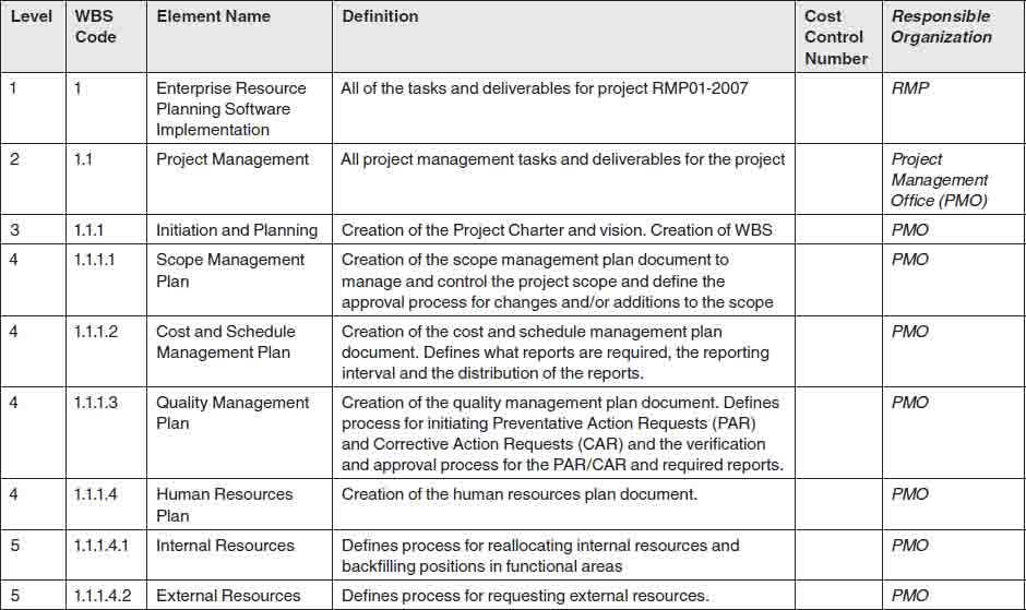
11. THE RURAL MEAT COMPANY, ERP IMPLEMENTATION—CLASS PROJECT
Dr. Ginger Levin is the instructor for a University of Wisconsin–Platteville, Master of Science in Project Management program. This WBS example was developed in October 2007 for the Project Scope Management Course #7080 by her students Dennis Kohlmeier, Daniel Nightingale, John Pando, and Denise Paus.
The author has edited the analytical and explanatory material accompanying the WBS to reduce the size, but the WBS, the WBS dictionary, and the WBS approach are the work of the student team.
Figure 10-15 is an example of a thoroughly thought-out WBS developed by a team and supported by a WBS dictionary. Although this WBS has minor problems, such as having only one subdivision to a particular WBS element, what’s important is the fact that it was developed by a team that understood the project in detail.
FIGURE 10-15 WBS—ERP Implementation


WBS Approach
The group used a top-down approach for the preparation of the WBS. Because the group did not have any appropriate templates to start with, they started deconstructing the project from the top. The starting place for the WBS was the scope statement for the project, which detailed what items would be included in the project. After items in scope were reviewed, the group constructed the level two items in the WBS. After each leg of the WBS was defined, the group then iteratively reviewed and refined each element of the WBS until it was fully decomposed. The group also used brainstorming techniques during the iterative decomposition, which helped to identify elements that should be included in the WBS. The creation of the WBS dictionary also assisted in making sure that the WBS contained sufficient detail to successfully manage the project.
For this project, the top-down approach was most appropriate because it allowed the team to progressively develop and understand the project as the creation of the WBS progressed. The top-down approach also allowed team members to apply their specific knowledge to the areas being decomposed in order to ensure that the WBS element was appropriately and completely defined. The top-down approach was also appropriate due to the custom nature of the project and because only specific elements of the ERP system are being implemented along with several interfaces with other systems. Because of this, a bottom-up method would not be appropriate, because the high-level details of the project need to be understood and captured before the lower-level details can be developed. The group did refer to existing WBS templates to help guide the process and help determine the level of decomposition that should occur.
Utilizing a top-down approach does introduce several challenges to the project, because it is likely that work packages will be overlooked if the appropriate individuals are not involved in the process. It is also likely that the WBS definition could take a significant amount of time as the project team progresses through the decomposition iterations. It is important that the project stakeholders are involved in reviewing the WBS so that they can verify that the detail is sufficient and covers all project deliverables. The stakeholders may also be able to identify items that were previously missed. However, at this point it is important to be cognizant of the project scope and to not introduce items that are outside the baseline project scope statement. If items are identified that need to be included but are outside the project scope, the changes are to be identified and submitted to the change management process.
The WBS for project RMP01-2007 will provide the foundation for integrating and relating all project work, such as scope, schedule, and cost. This WBS is a complete quality-oriented document that will provide the Project Management Office with the ability to efficiently identify and assign tasks as well as track costs and schedules throughout the life cycle of the project. This WBS will provide the framework to enable the project team to successfully execute the project plan with the confidence that all the tasks for the project have been identified.
The WBS dictionary developed by the team is presented in Figure 10-16.
FIGURE 10-16 WBS Dictionary ERP Implementation


12. ROAMING TO WIN PROJECT AT NATIONAL WIRELESS, INC.—CLASS PROJECT
This example was developed by Tonia Glasgow, Heather Dunn, Scott Sedlacek, and Abhijit Vengsarkar for the Project Scope Management Course #7080 for Dr. Ginger Levin, an instructor for the University of Wisconsin–Platteville Master of Science in Project Management program.
Below is the WBS, which, according to the team, is to be applied during the implementation of the “Roaming to Win” project at “National Wireless, Inc.” (NWI), a fictitious entity.
The basic WBS presented in Figure 10-17 was developed by the class. There has been some reformatting of the WBS by the author to conserve space, and the written material originally submitted has been significantly reduced and edited, although the basic material that explains the WBS was developed by the team.
The one significant change the author would recommend would be to recognize that the WBS is for a program consisting of several phases (1.1–1.7, except for 1.2). As a result, the author would have moved “1.2 Project Management” to become “1.1 Program Management” at Level 2 and would have renumbered the WBS. The other item is to note that it is normally poor practice to have only one breakdown under a summary element, whether a WBS or an outline; that is, “1.2.3 Scope Statement/SOW” in Figure 10-17. It appears that “1.2.3.1 Scope Statement,” “1.2.3.2 SOW,” and “1.2.3.3 Change Requests” would be appropriate decompositions. Similarly, the breakdown of “1.7 Roaming Deployment” should be reviewed to either add more items under “1.7” at Level 2 or to move the third-level items up to the second level.
FIGURE 10-17 Roaming to Win Project WBS


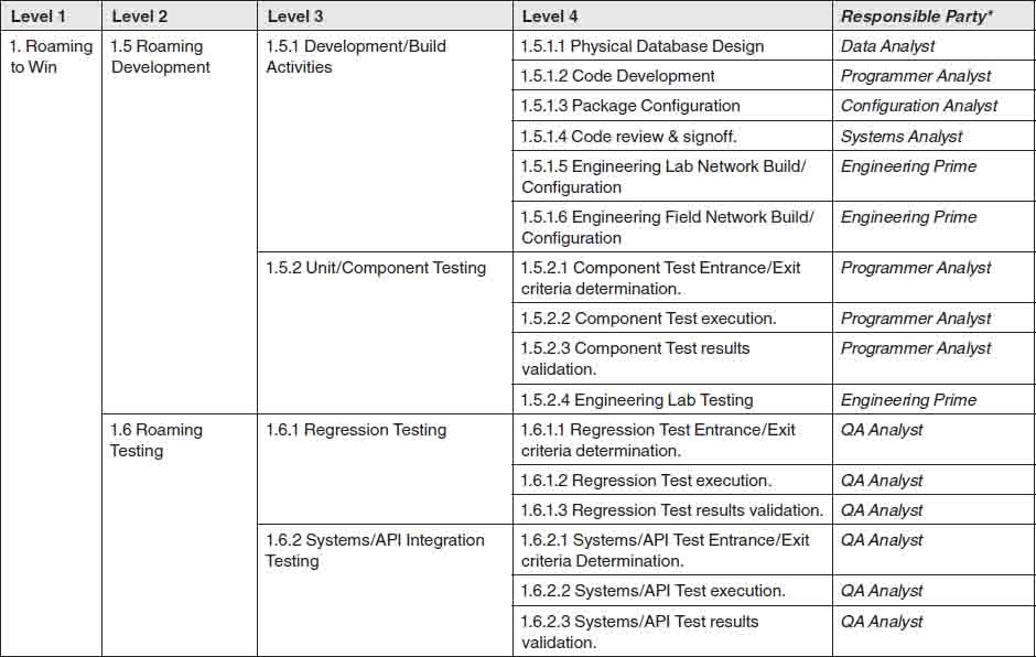

The class instructor, Dr. Levin, also provided some recommendations to the team. One comment was that some of the items in “1.3.1” should have been further decomposed to Level 5. The reviews and signoffs of the various requirements, such as “1.3.1.2,” should have been decomposed to the next level, which would have been more suitable as work packages that had one person/organization responsible for the work.
As stated by the class group, this WBS is a strategic tool to be utilized by the various teams from the different Business Units (BUs) that work collectively in the implementation of the “Roaming to Win” project at NWI.
WBS Analysis
The WBS was structured to comply with the 100 percent rule so as to include all the requirements defined in the scope statement for the “Roaming to Win” project. The WBS was decomposed to appropriate levels as necessary, sometimes going down to the fourth level to help define work effort that could be easily understood by the different teams. The WBS has responsibilities associated with the WBS elements that help provide clear lines of responsibility and accountability between the different stakeholder BUs. The WBS is structured on a hierarchical basis, where the child WBS elements collectively contain all the work defined at the parent level, and it has a simple coding scheme to identify each WBS element. This system helps provide effective reporting and control mechanisms and thereby makes it easier to monitor project progress. Creating a sufficient level of detail on the WBS helps identify issues and risks early in the project so that they can be handled in an immediate and effective manner.
The WBS also has unique “Roaming to Win” characteristics (use-related) reflected in its structure, as can be seen in the Engineering- and IT-based work elements that follow the Software Development Life Cycle (SDLC) principles. Structuring the WBS on SDLC principles and using appropriate terminology help provide clear communication between the IT team members about their work packages and responsibilities. The specific design-, development-, and testing-related work elements also are very specific to a telecom service delivery project, as is evident in this project.
The “Roaming to Win” WBS has been structured to provide decomposition at levels necessary to define, clarify, and monitor the completion of work packages as logically as possible. This logical grouping provides clean lines of responsibility with minimal overlap, especially where areas of integration occur. The logical grouping also allows for accountability at the appropriate level. The WBS has been constructed keeping in mind the 100 percent rule, anchored around a deliverable-oriented structure.
A top-down approach was used to develop the “Roaming to Win” WBS. The “Roaming to Win” project was conceived as a result of NWI’s limited footprint, which constrained the mobility of NWI customers. This project is expected to be the first of many such initiatives that NWI plans to launch with additional carriers. Due to NWI’s initial foray into the roaming space, it was expected that a number of additional deliverables would be uncovered during brainstorming sessions within the project planning stage. A top-down WBS is effective in accommodating additional deliverables and providing logical structuring in such a situation.
NOTES
1. RichardByrom.com. Online at http://www.richardbyrom.com (accessed April 18, 2008).
2. Department of Agriculture, Office of the Chief Information Officer, Information Technology Capital Planning and Investment Control Guide(Washington, D.C.: Department of Agriculture, April 2002).
3. Ibid., 70.
4. National Aeronautics and Space Administration, Work Breakdown Structure Reference Guide (Washington, DC: National Aeronautics and Space Administration, May 1994), D-4.