
Chapter 15
Macros
Macros and procedures are similar because they both call a sequence of instructions to be executed in the main program. Procedures save memory and programming time, but require linkage to invoke the procedure, which requires a CALL and a RET instruction.
A procedure is a set of instructions that perform a specific task. They are invoked from another procedure — the calling procedure (or program) — and provide results to the calling program at the end of execution. Procedures (also called subroutines) are utilized primarily for routines that are called frequently by other procedures. The procedure routine is written only once, but used repeatedly; thereby, saving storage space. Procedures permit a program to be coded in modules; thus, making the program easier to code and test.
A macro is a segment of code that is written only once, but can be executed many times in the main program. When the macro is invoked (or called), the assembler replaces the macro call with the macro code, which is essentially an instruction substitution procedure. The macro code is then placed in-line with the main program, which usually requires more memory than a similar procedure. Macros generally make the program more readable and increase program execution, because there is no CALL or RET instruction.
15.1 Macro Definitions
A macro is specified by a unique name followed by the macro directive (MACRO). The macro may include a parameter list with a comma separating each parameter; otherwise, there is no parameter list. This is followed by the body of the macro, which contains the instructions that define the macro. The macro code is terminated by the end macro directive (ENDM). Thus, the macro definition is bracketed by the MACRO and the ENDM directives.
A macro is a user-defined instruction that normally occurs at the beginning of a program or before the macro is called. The code between the MACRO and ENDM directives is a sequence of consecutive instructions that replace the macro being invoked. A general macro definition is shown below.
macro_name MACRO optional parameter list
assembly language instructions
ENDM
The macro is then called from the main program, as follows:
macro_name optional parameter list
An example of a simple macro definition, called CALC, is shown in Figure 15.1, which adds two single-digit integers. The macro is called in the main program and includes the list of parameters that are to be utilized by the macro. Macro arguments A and B correspond to integers 3 and 4, respectively. Figure 15.2 shows the resulting code after the CALC macro has been invoked.
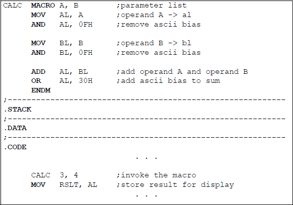
Illustrates the use of a macro to add two single-digit integers showing the macro definition and invoking the macro.

A macro can be called many times in a program and the code in a macro is reproduced each time the macro is invoked; however, there is only one macro definition in a program. Figure 15.3 shows a complete assembly language program that illustrates using the CALC macro, as defined in Figure 15.1 and Figure 15.2. The CALC macro is invoked twice using different arguments (parameters) and the resulting sums are then displayed. The arguments cannot designate a CPU register. The macro is defined at the beginning of the program before any segment is declared so that it can replace the macro reference where it is invoked in the program. Since the macro is called twice, two different result areas are required to store the two sums that will be displayed.
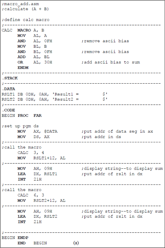

Assembly language program invoking the CALC macro twice to add two single-digit integers: (a) the program and (b) the outputs.
15.2 Macro Examples
This section presents examples using macros with and without parameters. The examples consist of arithmetic operations, a code conversion program, and a sorting program that sorts numbers in ascending numerical order, among others.
Example 15.1 This example uses a macro that contains no parameters. The program adds a 2-digit augend and a 2-digit addend that are entered from the keyboard. The assembly language program uses the ASCII adjust after addition (AAA) instruction in the execution of the program. Figure 15.4 shows the parameter list (PARLST) in the data segment that contains the augend in OPFLD and OPFLD + 1 and the addend in OPFLD + 2 and OPFLD + 3. Figure 15.5 illustrates the program to calculate the sum of the two operands.

Parameter list containing the 2-digit augend and the 2-digit addend that are entered from the keyboard as hexadecimal numbers.
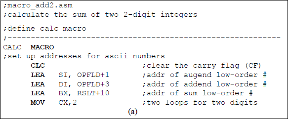
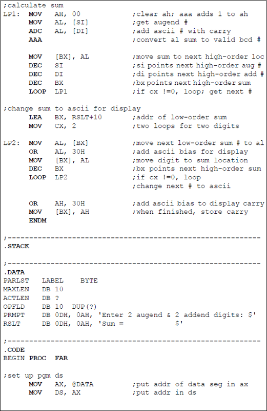

Program that uses a macro to add two 2-digit operands: (a) the program and (b) the outputs.
Example 15.2 This example uses three calls to a macro that contains two parameters. The program obtains the product of two unpacked single-digit BCD operands. The assembly language program uses the ASCII adjust AX after multiplication (AAM) instruction in the execution of the program. Figure 15.6 illustrates the assembly language program to calculate the product of the two operands.


Program using three macro calls to obtain the product of two unpacked BCD operands: (a) the program and (b) the outputs.
Example 15.3 This example presents an assembly language program that converts a binary code to the corresponding Gray code. The Gray code belongs to a class of cyclic codes called reflective codes and is an unweighted code where only one input changes between adjacent code words. The ith Gray code bit gi can be obtained from the corresponding binary code word by the following algorithm:
for 0 ≤ i ≤ n – 2, where the symbol ⊕ denotes modulo-2 addition defined as:
Using the algorithm shown in Equation 15.1, an 8-bit binary code can be converted to the corresponding 8-bit Gray code, as follows:
Gray |
Binary |
|
|---|---|---|
g7 |
= |
b7 |
g6 |
= |
b6 ⊕ b7 |
g5 |
= |
b5 ⊕ b6 |
g4 |
= |
b4 ⊕ b5 |
g3 |
= |
b3 ⊕ b4 |
g2 |
= |
b2 ⊕ b3 |
g1 |
= |
b1 ⊕ b2 |
g0 |
= |
b0 ⊕ b1 |
For example, a binary code word of 10001101 converts to the corresponding Gray code word of 11001011, as shown in Figure 15.7.

Figure 15.8 shows the parameter list (PARLST) in the data segment that contains representative binary data that was entered from the keyboard and stored in the OPFLD section. This data will be used by an assembly language program presented in this example. The first bit entered is the high-order bit and is stored in location OP (OPFLD + 0). The eight bits of the OPFLD depict a binary number of 10001101 in hexadecimal notation, which includes the ASCII bias of 3 for numerical digits. The appropriate bits are then exclusive-ORed, the ASCII bias is added to the result, and the resulting Gray code bit is stored in the result area (RSLT). When two ASCII digits are exclusive-ORed, the result is a digit with no ASCII bias.
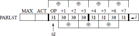
Example of binary data entered from the keyboard and stored in the OPFLD location of the parameter list.
Figure 15.9 illustrates an assembly language program — using a macro (BIN_GRAY) with no parameters — to translate an 8-bit binary code word to the corresponding 8-bit Gray code word. The binary data is entered from the keyboard. Since no operation is required to translate the high-order binary bit to the high-order Gray code bit, a count of seven is entered in the counter general-purpose register CX — Gray code bit g7 is obtained directly from the binary bit b7.
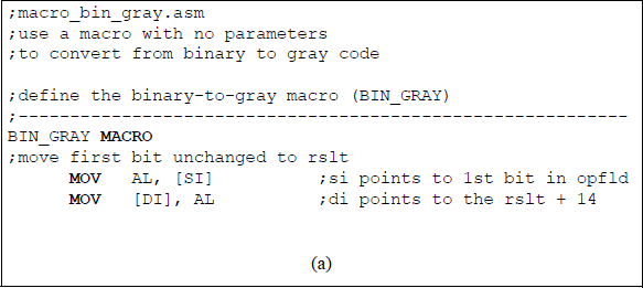
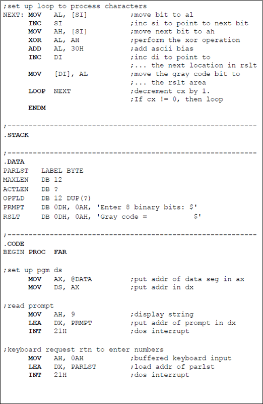
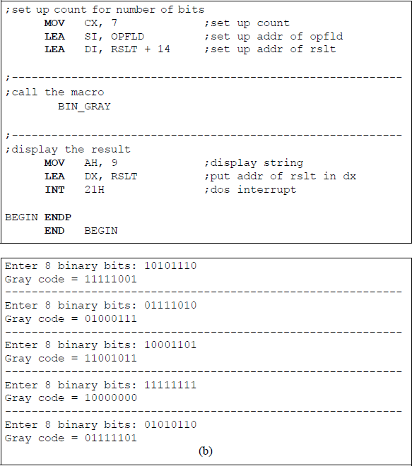
An assembly language program to translate an 8-bit binary code word to the corresponding Gray code word: (a) the program and (b) the outputs.
Example 15.4 Figure 15.10 illustrates an assembly language program to calculate the area of a triangle from two single-digit integers using a macro with two parameters. The parameters represent the base and the height of a triangle. The ASCII bias is removed from the parameters and the base is divided by two using a shift logical right (SHR) instruction. The result is then multiplied by the height and converted to two unpacked decimal numbers in register AX by the ASCII adjust AX after multiply (AAM) instruction. The product is then converted to ASCII for display. The macro labelled AREA is invoked three times.


Program to calculate the area of a triangle using a macro with two parameters: (a) the program and (b) the outputs.
Example 15.5 Figure 15.11 presents an assembly language program that utilizes a macro to sort ten single-digit integers — that are entered from the keyboard — in ascending numerical order. Since there are ten digits, only nine comparisons are required. Also, it is not necessary to remove the ASCII bias from the digits, because all the numbers have the same bias — the only difference is the low-order four bits.
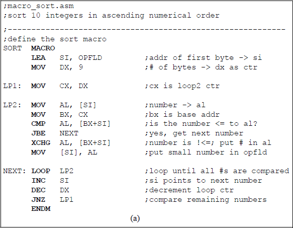

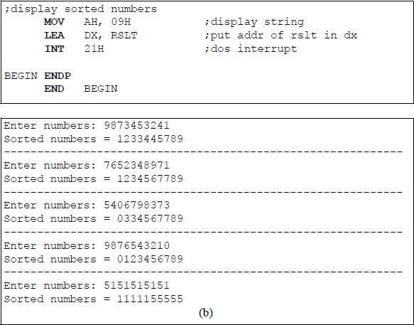
Program to sort ten single-digit integers in ascending numerical order using a macro: (a) the program and (b) the outputs.
Each number is compared to all the other numbers in the OPFLD to determine the smallest number, which is then stored in the next lower-order location of the OPFLD area of the parameter list. The program enters five separate 10-digit sequences, then displays the sorted numbers in ascending numerical order.
Example 15.6 This example uses a macro in a program to detect odd parity in an 8bit code word that is entered from the keyboard. The parity bit is an extra bit that is added to a code word to make the overall parity — the code word bits plus the parity bit — contain either an odd or an even number of 1s, as shown in Table 15.1 for both odd and even parity using a 4-bit code word.
Parity Bit Generation
Code Word |
Parity Bit (odd) |
Code Word |
Parity Bit (even) |
|---|---|---|---|
0000 |
1 |
0000 |
0 |
0001 |
0 |
0001 |
1 |
0010 |
0 |
0010 |
1 |
0011 |
1 |
0011 |
0 |
0100 |
0 |
0100 |
1 |
0101 |
1 |
0101 |
0 |
0110 |
1 |
0110 |
0 |
0111 |
0 |
0111 |
1 |
1000 |
0 |
1000 |
1 |
1001 |
1 |
1001 |
0 |
1010 |
1 |
1010 |
0 |
1011 |
0 |
1011 |
1 |
1100 |
1 |
1100 |
0 |
1101 |
0 |
1101 |
1 |
1110 |
0 |
1110 |
1 |
1111 |
1 |
1111 |
0 |
The parity bit can be generated by modulo-2 addition, as previously defined in Example 15.3. Equation 15.2 depicts a method to maintain even parity for a 4-bit message m3 m2 m1 m0 using modulo-2 addition. The parity bit for odd parity generation is the complement of Equation 15.2.
Parity implementation can detect an odd number of errors, but cannot correct the errors, because the bits in error cannot be determined. If a single error occurred, then an incorrect code word would be generated and the error would be detected. If two errors occurred, then the parity would be unchanged and still be correct; however, the code word would be incorrect.
Figure 15.12 shows the parameter list containing one of the 8-bit code words — 10001101 — that will be used in the program. Bits (30H) and (31H) are hexadecimal notations for binary bits 0 and 1, respectively. Since the exclusive-OR function will be used in the macro, the ASCII bias does not have to be removed. Register SI points to the first bit in the OPFLD area of the parameter list.

Example of the parameter list for a program to detect the parity in an 8-bit code word.
Figure 15.13 shows the program utilizing a macro called PARITY that contains no parameters. General-purpose register BL is used to contain the generated odd parity bit for the 8-bit code word. The register is initialized to a value of 01H and will be toggled when each code word bit is examined, depending on the bits in the code word. Register CX contains a value of eight, which is the number of bits in the code word, and will be used with the LOOP instruction in the macro.

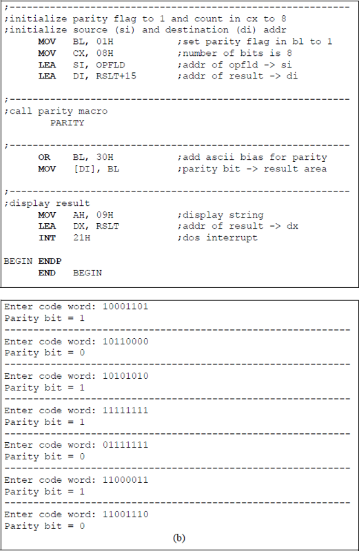
Program to generate the odd parity bit for an 8-bit code word: (a) the program and (b) the outputs.
15.3 Problems
All of the programs in this section are to be written in assembly language, not embedded in a C program.
15.1 Design a program using a macro that adds two single-digit packed BCD operands that are entered from the keyboard and display the results. Use hexadecimal characters 0 through 9 and higher-valued hexadecimal numbers as valid packed BCD numbers, such as the ASCII characters @ (40H) through Y (59H) and ‘ (60H) through y (79H). For example, 2 (32H) + R(52H) = 084 and s(73H) + 9(39H) = 112.
15.2 Write a program using a macro that sorts from two to ten single-digit integers in ascending numerical order that are entered from the keyboard. Enter several different sets of integers ranging from two integers to ten integers and display the results.
15.3 Write a program using a macro that is invoked twice to exchange two single-digit integers and to exchange two alphabetic characters and display the results. The macro is defined using two parameters.
15.4 Write a program using a macro to reverse the order and change to uppercase — if necessary — all alphabetic characters that are entered from the keyboard. Enter several sets of characters of different lengths, both lowercase and uppercase, and display the results.
15.5 Write a program that uses two macros. One macro generates an odd parity bit for an 8-bit code word that is entered from the keyboard. If the parity is odd, then display a 0; if the parity is even, then display a 1. The other macro removes all nonletters from data that are entered from the keyboard.
15.6 Write a program that uses two macros. One macro is called twice to switch the locations of two characters that are listed as parameters. The other macro has no parameters and makes all characters uppercase that are entered from the keyboard. It also reverses the order of the characters.
15.7 Write a program using a macro with no parameters that adds two single-digit integers that are entered from the keyboard. Enter several integers and display the results.
15.8 Write a program using a macro with no parameters that multiplies two single-digit integers that are entered from the keyboard. Enter several integers and display the results.
15.9 Write an assembly language program — not using a macro — that performs subtraction on two 2-digit integers. The program can easily be changed to a macro-oriented program by simply placing the arithmetic part of the program within the macro segment. Enter several different sets of integer pairs in which the entire minuend is greater than, equal to, or less than the entire subtrahend. Also enter integers in which the individual minuend digits are greater than, equal to, or less than the individual subtrahend digits. Display the results of all operations. If the subtraction operation results in a negative difference, then display a negative sign for the result. The parameter list is shown below for this problem.
