
Chapter 16
Interrupts and Input/Output Operations
An interrupt is an asynchronous occurrence that is generally initiated by an input/output device; for example, the device is ready to transfer data or to receive data. When an interrupt occurs, the processor stops execution of the current operation and transfers control to a procedure that is specifically designed to handle the interrupt. Application programs can access these procedures — whose addresses are located in an interrupt descriptor table (IDT) of the operating system — by means of instructions that are similar to the procedure CALL instruction. The IDT provides access to predefined and used-defined interrupts and each entry in the IDT is identified by an interrupt vector number.
An exception is similar to an interrupt, but is a synchronous event caused by a predefined condition that occurs during the execution of an instruction. This chapter also provides an introduction to input/output operations, such as direct memory access (DMA), memory-mapped I/O, and the input/output instructions (IN/OUT).
16.1 Interrupts
This section provides a brief introduction to calling interrupts and returning from interrupts. When an interrupt occurs, the processor suspends operation of the current program and pushes the contents of the following registers onto the stack: first the EFLAGS register, then the code segment (CS) register, and then the instruction pointer (EIP) register. The processor also resets the interrupt enable flag (IF) so that any additional interrupts will not affect the execution of the interrupt program. An error code may also be pushed onto the stack.
A software-generated interrupt is initiated by the call to interrupt procedure (INT n) instruction, which is a typical mnemonic for a call to an interrupt handler. The syntax for a typical interrupt call is shown below.
INT immed8 //immed8 is an immediate
//byte that specifies an
//interrupt vector number
The destination operand of an interrupt or exception specifies an address range of 0 to 255 in the IDT, where each address contains an offset of 8-byte descriptors (protected mode) or 4-byte interrupt vectors (real-address mode: IP:CS). The IDT is referred to as the interrupt vector table (IVT) in real-address mode. The contents of the IDT and IVT addresses point to an operating system procedure for a particular type of interrupt. There are 18 predefined interrupts and exceptions, 224 user-defined interrupts, and 13 addresses in the IDT that are reserved.
Return from an interrupt is generated by the interrupt return (IRET) instruction, which is similar to the procedure far return (RET) instruction. The IRET instruction pops the previous contents of the CS register, the EIP register, and the EFLAGS register from the stack that were pushed onto the stack by the interrupt. The stack pointer (ESP) register is incremented to the correct setting and execution of the interrupted program continues at the instruction immediately following the INT instruction. Four typical interrupt vectors are shown below.
The INT 00H instruction is used to generate an interrupt for divide by zero.
INT 00H //generates an interrupt for//DIV and IDIV instructions if an//attempt is made to//divide by zero,//located at address 000HThe INT 04H instruction is used to generate an interrupt for divide overflow.
INT 04H //generates an interrupt for a//an arithmetic operation if//the overflow flag is set,//located at address 010HThe INT 21H instruction is used to generate an interrupt for screen display using a function code of 09H. This interrupt is used to display a string that is entered elsewhere in the program and is terminated by a $ sign (24H). The string is bracketed by apostrophes. All the INT 21H instructions require a function code to be stored in general-purpose register AH prior to executing the INT 21H instruction.
INT 21H //A function code of 09H in AHThe INT 21H instruction is used to generate an interrupt for buffered keyboard input using a function code of 0AH. This interrupt is used to store a character string that is entered from the keyboard into a parameter list. All the INT 21H instructions require a function code to be stored in general-purpose register AH prior to executing the INT 21H instruction.
INT 21H //A function code of 0AH in AH
The interrupt flag (IF) in the EFLAGS register can be set by the set interrupt flag (STI) instruction. When the IF flag is set by the STI instruction, the processor commences responding to maskable interrupts after the next instruction has been executed, permitting interrupts to be enabled just prior to returning from a procedure. Interrupts can be masked by an external device so that they are ignored by the processor. Nonmaskable interrupts are those that must be acknowledged by the processor. The IF flag can be reset by the clear interrupt flag (CLI), permitting the processor to disregard maskable interrupts.
Input/output devices have highest priority over central processing units when transferring data to or from main memory, because they are inherently slower and cannot have the data transfer stopped temporarily. Disk drives and tape drives are examples of I/O subsystems in this category. This may be resolved by including in the I/O device data bus hardware a first-in, first-out (FIFO) buffer to temporarily store the data during a data transfer operation. Another technique is to grant the I/O device bus control when requested — a process called cycle stealing from the CPU, although this decreases the speed of the CPU.
In summary, interrupts transfer control from the current program to an interrupt service routine (ISR) when an internally or externally generated interrupt request has been generated. Internally generated interrupt requests originate from the CPU — for example, when a divide by zero, a divide overflow, or an INT 21H instruction occurs. Externally generated interrupt requests are asynchronous events that originate from an I/O device and suspend the currently running CPU program. When the interrupt operation is completed, the CPU restores the appropriate registers and returns to the interrupted program.
16.2 Direct Memory Access
Direct memory access (DMA) allows an I/O device control unit to transfer data directly to or from main memory without CPU intervention. This is a much faster data transfer operation allowing both the processor and the I/O device to operate concurrently in most cases. The DMA technique is used primarily to transfer large amounts of data between the I/O device and main memory without continual intervention by the CPU. DMA transfers involve a device control unit specifically designed for DMA operations and replaces software with hardware.
When the CPU receives a DMA request from an I/O device, it suspends its operation at certain breakpoints and releases control of the memory bus, address bus, and control signals, then asserts an acknowledgement to the I/O device. Possible breakpoints are shown in Figure 16.1 for a typical instruction cycle. These breakpoints allow the processor to suspend execution of the current program without loss of program continuity. The breakpoints occur just prior to when the processor requires use of the buses. Interrupt breakpoints are allowed only at the end of an instruction cycle.

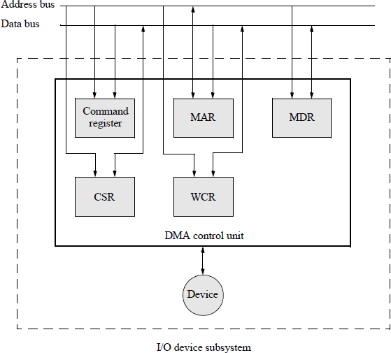
Figure 16.2 shows a typical I/O device subsystem containing a dedicated DMA control unit and I/O device for a single-bus structure. The DMA device control unit contains the following registers:
A memory data register (MDR), which contains the data to be transferred to memory or received from memory.
A memory address register (MAR), which contains the starting address in memory where the data is to be stored or from where the data is to be retrieved. When a word of data is transferred to or from memory, the contents of MAR are incremented to the next contiguous address.
A word count register (WCR), which is used to determine the number of words to be transferred. When a word of data is transferred to or from memory, the contents of WCR are decremented by a value of one.
A command register, which is used to contain the type of DMA operation to be performed — either a read or a write operation. The register may contain several different commands depending on the I/O device. This information may be contained in a separate control and status register.
A control and status register (CSR), which may contain information on the status of the device — whether the device is ready, the type of data transfer operation — read or write, any errors that occured during the data transfer operation, an enable interrupt bit, and any other bits that are specific to the type of I/O device.
A DMA transfer is initiated by the CPU by sending the device control unit the starting memory address, the number of words to be transferred, and a read or write command. When the data transfer is complete, the control unit signals the CPU by asserting an interrupt signal.
The address bus addresses all five blocks shown in Figure 16.2. The data bus contains the appropriate information depending on the specific register that is addressed. The CPU loads the starting address of memory into MAR, then loads the number of words to be transferred into WCR, then sends the command (read or write) to the command register — alternatively, the command may be placed in the CSR. The WCR may send data to the CPU that represents a residual count; that is, a count indicating that not all data was transferred to or from memory.
The command register in Figure 16.2 may contain several different commands depending on the type of I/O device. For example, a tape drive can be issued any of the following commands, among others:
A read command to read a record on tape.
A write command to write a record on tape.
A rewind command to rewind the tape to the beginning of tape.
A back space command to back space over a record or to back space over a specific number of records.
A forward space command to forward space over a record or to forward over a specific number of records.
A write end of file command.
16.3 Memory-Mapped I/O
For single-bus machines, the same bus can be utilized for both memory and I/O devices. Therefore, I/O devices may be assigned a unique address within main memory, which is partitioned into separate areas for memory and I/O devices. Using the memory-mapped technique, I/O devices are accessed in the same way as memory locations, providing significant flexibility in managing I/O operations. Thus, there are no separate I/O instructions, and the I/O devices can be accessed utilizing any of the memory read or write instructions and their addressing modes.
The memory space of an I/O device is associated with a specific set of address values used as registers. Therefore, when the CPU generates a memory address, it may refer to a main memory address or to a register in an I/O device, depending on the address. Using an I/O-mapped technique, I/O devices are accessed using the IN and OUT type of instructions described in Section 16.4.
Figure 16.3 illustrates the organization for a typical memory-mapped I/O structure. A set of four interface paths is required to communicate with memory and I/O devices: a data bus, an address bus, a read signal, and a write signal. The CPU decodes a memory reference instruction, then activates the read or write control signal. This initiates either a memory access cycle or an I/O transfer, depending on the address.
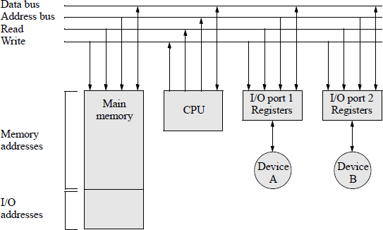
Communicating to an I/O device, therefore, is the same as reading and writing to memory addresses that are dedicated to the I/O device. The same protocol is used to communicate with the CPU and an I/O device as with the CPU and main memory. An I/O port is handled the same as a memory location; however, the memory-mapped I/O technique reduces the number of addresses available for main memory.
16.4 In/Out Instructions
There are two types of instructions that are specifically designed to communicate with I/O subsystems: IN and OUT. The IN instruction transfers data from an I/O port to register AL, AX, or EAX, depending on the size of the input data. The OUT instruction transfers data from register AL, AX, or EAX to an I/O port, depending on the size of the output data. These are referred to as register I/O instructions. The input or output port is specified by either an immediate byte or the contents of register DX.
There are also two types of instructions that are specifically designed to transfer string data between memory and an I/O port: INS and OUTS. The INS instructions transfer string data from an I/O port to memory. These are INSD, INSW, and INSB, which transfer doubleword, word, or byte data, respectively. The OUTS instructions transfer string data from memory to an I/O port. These are OUTD, OUTW, and OUTB, which transfer doubleword, word, or byte data, respectively. These are referred to as string (block) I/O instructions. The input or output port is specified by either an immediate byte or the contents of register DX.
The operation of the string I/O string instructions is similar to the string instructions presented in Chapter 13. The (E)SI and (E)DI registers are used for string operations as source and destination pointers, respectively — they point to string and destination memory elements. The repeat (REP) prefixes specify the condition for which the instruction is to be executed. The general-purpose registers (E)SI and (E)DI are automatically incremented or decremented after each repetition of the string instruction to point to the next byte, word, or doubleword to implement block moves for string operations.
16.4.1 Register I/O IN Instructions
There are six categories of the IN instruction referred to as register I/O instructions: three using immediate operands to indicate the port address for byte, word, or doubleword operands; and three using general-purpose register DX to indicate the port address for byte, word, or doubleword operands.
The syntax for the three IN instructions using immediate port addresses is shown below, where the source operand is the I/O port and the destination operand is a general-purpose register.
IN register, immediate (input from port specified by
immediate to AL, AX, or EAX)
The syntax for the three IN instructions using DX to contain the port addresses is shown below, where the source operand is the I/O port address in DX and the destination operand is a general-purpose register.
IN register, DX (input from port specified by
DX to AL, AX, or EAX)
If an immediate byte operand is used to specify the port address, then the address has a range from 0 to 255 (28 – 1); if register DX is used to specify the port address, then the address has a range from 0 to 65,535 (216 – 1). No flags are affected by the IN instructions.
16.4.2 Register I/O OUT Instructions
There are six categories of the OUT instruction referred to as register I/O instructions: three instructions using immediate operands to indicate the port address for byte, word, or doubleword operands; and three instructions using general-purpose register DX to indicate the port address for byte, word, or doubleword operands.
The syntax for the three OUT instructions using immediate port addresses is shown below, where the source operand is a general-purpose register and the I/O port address is the destination immediate operand.
OUT immediate, register (output from AL, AX, or EAX
to port specified
by immediate value)
The syntax for the three OUT instructions using DX to contain the port addresses is shown below, where the source operand is a general-purpose register and the destination operand in DX contains the I/O port address.
OUT DX, register (output from AL, AX, or EAX
to port specified by DX)
If an immediate byte operand is used to specify the port address, then the address has a range from 0 to 255 (28 – 1); if register DX is used to specify the port address, then the address has a range from 0 to 65,535 (216 – 1). No flags are affected by the OUT instructions.
16.4.3 String I/O IN Instructions
A string is a sequence of bytes, words, or doublewords that are stored in contiguous locations in memory as a one-dimensional array. Strings can be processed from low addresses to high addresses or from high addresses to low addresses, depending on the state of the direction flag (DF). If the direction flag is set (DF = 1), then the direction of processing is from high addresses to low addresses — also referred to as auto-decrement. If the direction flag is reset (DF = 0), then the direction of processing is from low addresses to high addresses — also referred to as auto-increment. The state of the direction flag can be set by the set direction flag (STD) instruction and can reset by the clear direction flag (CLD) instruction. The direction flag is located in bit 10 of the 32bit EFLAGS register.
The input from port to string (INS) instructions transfer a string element — byte, word, or doubleword — from the I/O port designated by the source operand to the destination operand located in memory. The source (second) operand is an I/O port address contained in general-purpose register DX. The destination (first) operand is a memory location specified by the contents of registers ES:DI, ES:EDI, or RDI for 16, 32, or 64 addresses, respectively.
After the transfer is completed, the destination register DI, EDI, or RDI is automatically incremented or decremented depending on the state of the direction flag (DF) in the EFLAGS register. Thus, after each repetition of the string instruction the registers point to the next byte, word, or doubleword to implement block moves for string operations. There are two types of string I/O IN instructions: the explicit-operands form and the no-operands form, as described below.
Explicit-operands form instructions The explicit-operands form explicitly specifies the source and destination operands as part of the INS instruction. The address of the I/O source operand port is in register DX and the destination operand is a memory location whose size is explicitly defined as 8, 16, or 32 bits. There are three input from port to string INS instructions that have explicit operands, as shown in the syntax below.
INS memory, DX (transfer byte, word, or doubleword
from I/O port to a memory location
specified by the contents of
ES:(E)DI or RDI)
No-operands form instructions The no-operands form specifies the size of the operands by the mnemonic; for example, the INSW instruction specifies a word transfer from an I/O port to memory. Like the explicit-operands form, the no-operands form assumes that the address of the source operand port is contained in register DX and the destination memory operand is determined by contents of registers ES:(E)DI or RDI. The syntax for the three no-operands INS instructions is shown below.
INSB (transfer a byte from port addressed by
DX to memory addressed by ES:(E)DI or RDI)INSW (transfer a word from port addressed by
DX to memory addressed by ES:(E)DI or RDI)INSD (transfer a doubleword from port addressed by
DX to memory addressed by ES:(E)DI or RDI)
After the transfer is completed, the destination register DI, EDI, or RDI is automatically incremented or decremented depending on the state of the direction flag (DF) in the EFLAGS register, as stated previously. If the direction flag is set, then the direction of processing is from high addresses to low addresses; if the direction flag is reset, then the direction of processing is from low addresses to high addresses.
The input from port to string instructions can utilize the repeat (REP) prefixes to specify the condition for which the instruction is to be executed. A count in register (E)CX specifies the number of bytes, words, or doublewords that are transferred from the source I/O port to the memory destination for block transfers.
16.4.4 String I/O OUT Instructions
The output string to port (OUTS) instructions transfer a string element — byte, word, or doubleword — from a source operand in a memory location to the I/O port destination operand. The source (second) operand is a memory location specified by the contents of registers DS:SI, DS:ESI, or RSI for 16, 32, or 64 addresses, respectively. The destination (first) operand is an I/O port address contained in general-purpose register DX.
After the transfer is completed, the destination register SI, ESI, or RSI is automatically incremented or decremented depending on the state of the direction flag (DF) in the EFLAGS register. Thus, after each repetition of the string instruction the registers point to the next byte, word, or doubleword to implement block moves for string operations. There are two types of string I/O OUTS instructions: the explicit-operands form and the no-operands form, as described below.
Explicit-operands form instructions The explicit-operands form explicitly specifies the source and destination operands as part of the OUTS instruction. The address of the source operand is a memory location whose size is explicitly defined as 8, 16, or 32 bits. The source operand memory location is specified by the contents of the DS:SI, DS:ESI, or RSI registers. The address of the I/O port destination operand is in register DX. There are three output string to port OUTS instructions that have explicit operands, as shown in the syntax below.
OUTS DX, memory (transfer byte, word, or doubleword
from a memory location specified by
the contents of DS:(E)SI or RSI to
the I/O port addressed by DX)
No-operands form instructions The no-operands form specifies the size of the operands by the mnemonic; for example, the OUTSB instruction specifies a byte transfer from memory to an I/O port. Like the explicit-operands form, the no-operands form assumes that the address of the source operand is specified by the contents of registers DS:(E)SI or RSI and the contents of register DX specify the destination port address. The syntax for the three no-operands OUTS instructions is shown below.
OUTSB (transfer a byte from memory addressed by
DS:(E)SI or RSI to the port addressed by DX)OUTSW (transfer a word from memory addressed by
DS:(E)SI or RSI to the port addressed by DX)OUTSD (transfer a doubleword from memory addressed by
DS:(E)SI or RSI to the port addressed by DX)
After the transfer is completed, the destination register SI, ESI, or RSI is automatically incremented or decremented depending on the state of the direction flag (DF) in the EFLAGS register, as stated previously. If the direction flag is set, then the direction of processing is from high addresses to low addresses; if the direction flag is reset, then the direction of processing is from low addresses to high addresses.
The output string to port instructions can utilize the repeat (REP) prefixes to specify the condition for which the instruction is to be executed. A count in register (E)CX specifies the number of bytes, words, or doublewords that are transferred from the memory source to the destination I/O port for block transfers.
16.5 Problems
16.1 Define an interrupt and indicate the purpose of an interrupt.
16.2 Describe what happens when an interrupt occurs.
16.3 Explain why interrupt breakpoints occur only at the end of an instruction cycle.
16.4 Indicate which of the following instructions are valid or invalid.
IN AX, EA60H
IN AL, 297
16.5 Indicate the use of an interrupt with a vector of 00H.
16.6 Which interrupt type has a higher priority, maskable or nonmaskable interrupts?
16.7 Explain why DMA access to main memory has a higher priority than central processing units access to main memory.