
Chapter 3
Addressing Modes
X86 instructions can have zero or more operands; for example, a return (RET) instruction from a procedure (subroutine) can have no operands or an immediate operand; a negate (NEG) instruction forms the 2s complement of a single operand, NEG AX; a move instruction has two operands MOV AX, BX, which moves the contents of register BX to register AX. In the X86 instruction set, the first operand listed is the destination operand; the second operand listed is the source operand.
The instruction set provides various methods to address operands. The main methods are: register, immediate, direct, register indirect, base, index, and base combined with index. A displacement may also be present. These and other addressing methods are presented in this chapter together with examples. All arithmetic instructions with the exception of unsigned division (DIV) and signed division (IDIV) permit the source operand to be an immediate value.
The source operand can be obtained from the instruction as immediate data, from a general-purpose register, from a memory location, or from an input/output (I/O) port. The source operand is normally unchanged by the instruction execution. The result of an instruction execution can be sent to a destination in a register, a location in memory, or to an I/O port. Memory-to-memory operations are not permitted with single instructions — this type of operation is reserved for string instructions, which require that the source and destination locations be set up before the transfer takes place.
An instruction has the format shown below, where a label is an identifier for a line of code or a block of code, followed by a colon (:). The mnemonic is the name of the instruction, for example, ADD, SUB, MOV, etc. This is followed by zero to three operands — depending on the operation — separated by commas.
Some instructions require an operand to be a quadword (eight bytes), such as a dividend for a divide operation, or generate a quadword result, such as the product for a multiply operation. The dividend or product are contained in a concatenated register pair, such as EDX:EAX, where the colon specifies concatenation.
Addressing modes provide different ways to access operands. A displacement is an 8-bit, 16-bit, or 32-bit immediate value in the instruction and is used to address memory. A base is the contents of a general-purpose register (GPR). The registers normally used for this purpose are (E)BX and (E)BP. An index is the contents of a GPR. The registers that are normally used for this purpose are (E)SI and (E)DI.
b
3.1 Register Addressing
Using register addressing, the instruction selects one or more registers which represent the operand or operands. This is the most compact addressing method, because the register addresses are encoded in the instruction. It achieves fast execution since the operation is performed entirely within the central processing unit (CPU); that is, there are no bus transfers to or from memory. Examples of register addressing are shown below, where the semicolon indicates a comment.
INC BH ;increment register BH
MOV AX, BX ;move contents of register BX to register AX
SUB EBX, EBX ;subtract EBX from EBX (EBX = 0)
XOR EAX, EAX ;exclusive-OR EAX with EAX (EAX = 0)
The source and destination registers can be any of the general-purpose registers, either 8-bit, 16-bit, 32-bit, or 64-bit GPRs. The segment registers CS, DS, SS, ES, FS, or GS can also be used in register addressing as well as the flag register and the floating-point registers, among others. The length of the operand is determined by the name of the GPR.
3.2 Immediate Addressing
Some instructions have a data value encoded in the instruction so that it is available immediately as the source operand. The immediate data can be 8 bits, 16 bits, or 32 bits, which are sign-extended to fit the size of the destination operand. Examples of immediate addressing are shown below for both positive and negative values.
ADD EAX, 3 ;add 3 to register EAX
MOV AH, 00 ;reset AH; AH = 0000 0000
MOV EAX, 0ABCDFFFFH ;32-bit operand ABCD FFFF(Hex) = EAX
MOV AX, 302 ;AX = 0000 0001 0010 1110
MOV AX, - 40 ;AX = 1111 1111 1101 1000
3.3 Direct Memory Addressing
The memory operand can be either the source or the destination operand and is addressed by a segment selector and a 32-bit or 64-bit offset that is part of the instruction. The combination of the selector and the offset generates an effective address that points directly to the memory operand. The segment selector can be any of the following segment registers: code segment (CS), data segment (DS), stack segment (SS), or the extra segment (ES).
A segment selector is loaded with the appropriate value, then the CPU addresses memory using the current (implicit) selector and the offset. Explicit segment selectors are discussed in later section using a segment override prefix. Examples of direct memory addressing using an implicit segment selector are shown below.
MOV AL, [1A33D4H] ;AL = contents of memory at 1A33D4H
INC DWORD PTR [17H] ;incr 32-bit operand at offset 17H
3.4 Base (Register Indirect) Memory Addressing
Base, or register indirect, addressing is used when a register contains the address of the data, rather than the actual data to be accessed. This method of addressing uses the general-purpose registers within brackets; for example, [BX], [BP], [EAX], [EBX], etc., where the brackets specify that the indicated register contains an offset that points to the data within a specific segment. Registers (E)BX, (E)SI, and (E)DI contain offsets for processing operands in the data segment; for example, DS:BX, DS:ESI, and DS:DI. Register (E)BP is used to reference data in the stack segment, such as SS:EBP.
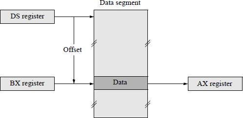
Examples of indirect memory addressing are shown below. In the first example, the notation [[EBX]] in the comments reads "the contents of the contents of EBX"; that is, the contents of memory specified by the contents of EBX are loaded into register ECX. In the second example, assume that BX = 0002H and that memory locations 0002H and 0003H contain 00H and FFH, respectively. Then register AX = FF 00H after completion of the move instruction, where 00H is the low-order byte in AL. This is illustrated in Figure 3.1.
MOV ECX, [EBX] ;ECX = [[EBX]]; If [EBX] = 1000H, then
;ECX = bytes [1000H through 1003H]
MOV AX, [BX] ;AX = [0002H] , [0003H]
3.5 Base or Index Plus Displacement Addressing
This is a variation of base addressing and uses the general-purpose registers (E)AX, (E)BX, (E)CX, (E)DX, (E)SP, (E)BP, (E)SI, or (E)DI as the base address or (E)AX, (E)BX, (E)CX, (E)DX, (E)BP, (E)SI, or (E)DI as an index address, plus a displacement to access memory. A scaling factor may also be used in conjunction with the index register. The displacement consists of a signed number in 2s complement representation that is added to the value in the base register or index register to produce an effective address. When (E)BP is utilized as the base register, the stack segment is the default segment.
An expression using a displacement is usually written as [BX + 4] using BX as the base register with a displacement of 4, or as [ESI + 8] using ESI as the index register with a displacement of 8. Both methods indicate a displacement of four or eight bytes from the base or index address stored in register BX or register ESI. This addressing method can be used as an index into an array, as shown in the code segment shown below, where the DB directive defines the five values as bytes. The compare instruction compares the contents of AL with the byte at location TABLE + 4, which is the fifth byte (4) of the list. The first element (15) of the list is at location TABLE, which has a displacement of zero. Changing the value of the displacement accesses different fields in the same record. Changing the base register accesses the same field in different records.
TABLE: DB 15, 7, 6, 10, 4
...
LEA BX, TABLE ;loads the effective
;addr of TABLE into BX
CMP AL, [BX + 4]
Base or index addressing provides a way to address tables, arrays, or lists which may be located in different areas of memory. A base register can be set to point to the base of a table. The elements of the table can then be addressed by their displacement from the base. Different tables can be addressed by simply changing the value in the base register. A graphical representation of this concept is illustrated in Figure 3.2, which shows relevant information regarding an employee. The contents of register BX can be changed to access a different employee, where the same displacement addresses the rate.

Alternatively, this addressing method can be used to access elements in an array. The displacement value locates the beginning of the array and the value stored in the index register selects an element in the array, as shown in Figure 3.3.

The effective address in Figure 3.3 is obtained from the sum of the displacement and the contents of index register ESI. Indexed addressing is used to access elements in an array at execution time. The value of the index register selects an element in the array; the first element is selected if the index register contains a value of zero. The elements are the same length; therefore, simple arithmetic on the index register will select any element. An instruction to move the contents of an array element to register EAX is shown below, where ARRAY is the address (displacement) of the array (or table) and the element is accessed whose index is in ESI.
MOV EAX, ARRAY[ESI]
ARRAY[ESI] references the contents of the element in the location addressed by the displacement ARRAY plus the contents of ESI — ARRAY + 0 references the first element in the array. To access the next element, simply increment register ESI.
3.6 Base and Index Plus Displacement Addressing
The effective address of the operand is obtained by adding the contents of the base register, the contents of the index register, and the displacement (which may be zero). Base indexed addressing without displacement is frequently used to access the elements of a dynamic array. A dynamic array is an array whose base address can change during program execution. This addressing method can also be used to access a 2-dimensional array in which the beginning of the array is determined by the displacement and the base register; the index register addresses the array elements.
Another application is to access elements in a 1-dimensional array on a stack, as shown in Figure 3.4. The base register can point to the stack top; the contents of the base register plus the displacement points to the beginning of the array. The index register then selects elements in the array. The effective address (EA) is calculated as shown below.
EA = EBP + displacement + ESI

Example 3.1 A 2-dimensional array is shown in Figure 3.5 in which the elements are stored row by row. The elements can be accessed by base-index with displacement addressing. The second element in the first row (56) can be accessed by
[EBX/EBP][ESI/EDI]
by storing the base address of the first element in BX/EBX (or BP/EBP) and storing a 1 in SI/ESI (or DI/EDI) with no displacement — the index register selects the ith element. A 1 rather than a 2 is stored in the index register, because the element whose address is in the base register is the first element (12). To access the second element in the second row (89), a value of 5 is added to the base register— the number of elements in a row — as shown below assuming a value of 1 in the index register.
5[EBX/EBP][ESI/EDI] or [EBX/EBP + ESI/EDI + 5]

3.7 Scale Factor
A scale factor can be used to access elements in an array in which the size of the elements is two, four, or eight bytes. The address calculation can be considered as
where the scale is 0, 1, 2, or 3. This addressing mode is useful for processing arrays and provides an index into the array when the array elements are two, four, or eight bytes. If the array elements are 8-byte operands, then the index register is multiplied by eight prior to calculating the effective address. Since the scale factor is a power of two, multiplication can be accomplished by shifting left rather than by a multiply operation.
(Index times scale) plus displacement The displacement points to the beginning of the array, while the index contains the address of the appropriate array element; that is, the index is the subscript of the array element. The effective address of the operand is obtained by multiplying the index by a scale factor of one, two, four, or eight and then adding the displacement.
Base plus (index times scale) plus displacement The effective address of the operand is obtained by multiplying the index register by a scale factor of one, two, four, or eight, then adding the base register, and then adding the displacement. This addressing mode is useful for accessing array elements in a 2-dimensional array when the operands are one, two, four, or eight bytes. An example is shown in Figure 3.6 using EBX as the base register, ESI as the index register with a scale factor of 4, and a displacement for the following move instruction that moves the addressed operand into register EAX:
MOV EAX, [EBX + ESI * 4 + DISPLACEMENT]

3.8 Segment Override Prefix
The processor selects the applicable default segment as a function of the instruction: instruction fetching assumes the code segment; accessing data in main memory references the data segment; and instructions that pertain to the stack reference the stack segment. When transferring data to or from memory, the processor usually references the current data segment as the default segment. However, a segment override prefix can be used to change the default data segment to another segment; that is, to explicitly specify any segment register to be used as the current segment.
This is accomplished by listing the new segment to be used for source or destination operands followed by a colon and is placed in front of the offset variable. For example, to override the data segment with the extra segment, the coding shown below applies to a move instruction, which moves the 32-bit operand addressed by register EBX in the extra segment to register EAX. When the move instruction is executed, the offset in register EBX pertains to the extra segment rather than the data segment.
MOV EAX, ES:[EBX]
The segment override prefix is a byte that is inserted in the instruction and causes the processor to fetch the memory operand from the designated segment rather than from the default segment. Some segments, however, cannot be overridden. Instruction fetches must be made from the code segment; push and pop operations must be made with reference to the stack segment; and string operations must provide a destination address in the extra segment.
The segment override prefix applies only to the instruction in which it is inserted; that is, it is restricted to a single instruction — all subsequent instructions use the default segment. Thus, the segment override prefix must be specified for each instruction that is to be overridden. Utilizing a segment override prefix increases the execution time of the corresponding instruction.
3.9 X86 Operation Modes
This section presents two of the operating modes for the X86 architecture for the basic execution environment: protected mode that allows for multiple tasks and multiple users and real mode. The operating modes are set by software and specify the instructions and architectural attributes that are available.
3.9.1 Protected Mode
Protected mode allows the system software to use features, such as virtual memory and multitasking, to increase system performance. The architecture provides four levels of protection: level 0 through level 3. Level 0 has the highest priority and is reserved for the operating system; levels 1 and 2 are for less critical operating system functions; level 3 is reserved for application programs.
Multitasking can execute several programs simultaneously. These programs (or tasks) may have separate segments or may share segments. The programs are written as if on a dedicated microprocessor. The multitasking software then simulates a dedicated microprocessor by allocating a virtual processor. The substitution of these virtual processors creates the appearance of a dedicated processor, where each task has an allotment of CPU time. If a task must wait for an I/O operation, it suspends its operation. The computer must be able to switch rapidly between tasks, save and load the entire machine state, prevent interference of tasks, and prioritize tasks.
Protected mode allows reliable multitasking and prevents tasks from overwriting code or data of another task. Thus, if a program fails, the effects are confined to a limited area and the operating system will not be affected. Protection is applied to segments and pages.
3.9.2 Real Mode
Real mode (or real-address mode), is an operating mode that implements the 8086 architecture and is initialized when power is applied or the system is reset. Thus, real mode allows compatibility with programs that were written for the 8086 processor. Real mode allows access to the 32-bit register set and protected mode when processor extensions are in effect. Real mode does not support multitasking.
The real-address mode implements a segmented memory consisting of 64 kilobytes in each segment. Each segment register is associated with either code, data, or stack, which are contained in separate segments. Real mode segments begin on 16-byte boundaries. Memory is accessed using a 20-bit address that is calculated by adding a right-aligned 16-bit offset to a segment register that is multiplied by 16; that is, the segment register is shifted left four bits. This provides an address space of 1 megabyte.
3.10 Problems
3.1 Specify the addressing mode for each operand in the instructions shown below.
(a) ADD AX, [BX]
(b) ADD CX, [BP + 8]
(c) ADD EBX, ES:[ESI − 4]
(d) ADD [EBP +EDI + 6], 10
3.2 Let DS = 1000H, SS = 2000H, BP = 1000H, and DI = 0100H. Using the real addressing mode with a 20-bit address, determine the physical address memory address for the instruction shown below.
MOV AL, [BP + DI]3.3 Let DS = 1100H, DISPL = –126, and SI = 0500H. Using the real addressing mode with a 20-bit address, determine the physical address memory address for the instruction shown below.
MOV DISPL[SI], DX3.4 Let the directive shown below be located in the data segment at offset 04F8H, where DW 10 DUP(?) specifies that a word is defined with an unknown value and duplicated ten times.
Let BX = 04F8H, SI = 04FAH, and DI = 0006H. Let the 10 reserved words beginning at location VALUE be labelled
Indicate the word that is referenced by the memory operand in each of the move instructions shown below.
(a) MOV AX, VALUE + 2(b) MOV AX, [BX](c) MOV AX, [SI](d) MOV AX, [BX + DI − 2]3.5 Differentiate between the operation of the following two move instructions:
(a) MOV EAX, 1234ABCDH(b) MOV AX, [1234H]3.6 Differentiate between the operation of the following two move instructions:
(a) MOV EBX, 1234ABCDH(b) MOV [EBX], 1234H3.7 Use base and index plus displacement addressing to obtain the physical address of the memory operand for the following conditions:
- 3.8 Obtain the real (physical) address that corresponds to each segment:offset pair shown below.
Segment: |
Offset |
|
|---|---|---|
(a) |
2B8C: |
8D21 |
(b) |
F000: |
FFFF |
(c) |
3BAC: |
90DF |