Chapter Eleven
Case Study 1
11.1 The Zero Bills Home launched at BRE Innovation Park, 2016.
A new model for designing cost-effective zero-carbon homes
Why do so few UK homes in the new-build sector offset all operational carbon emissions? Costs have come down and with improved reliability technologies become easier to use, yet national resistance to zero-carbon homes doggedly persists. The Zero Bills Home concept proposes linking technology and cost-based metrics to get the most out of zero-carbon housing design. We will explain why an optimised zero-carbon home can function more efficiently and economically than a building compliant with Part L of the 2013 Building Regulations. We also have thoughts on how zero-carbon homes could be marketed more effectively on their economic, rather than on their environmental or technical, attributes (fig. 11.1).
Introduction
As the cost of the ZEDlife tools reduces with economies of scale, and at the same time we have learnt from teething troubles early on how to close the performance gap between the expectations of design and the sometimes disappointing results of occupation, people are starting to question the benefit of centralised services provision to new buildings.
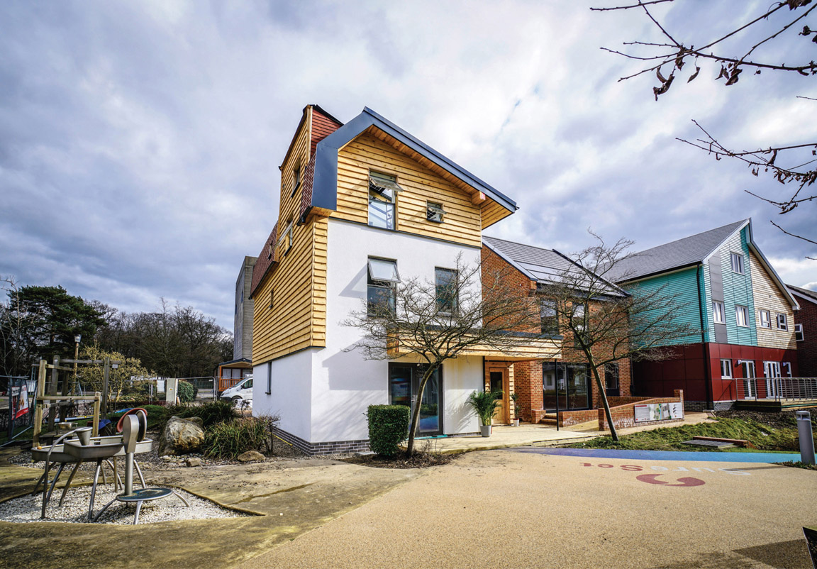
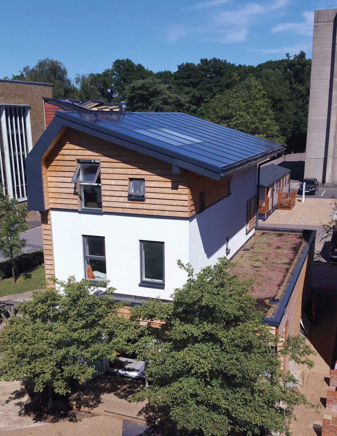
11.2 The Zero Bills Home build at the BRE Innovation Park represents the first show home for a new 96 home zero bills development in Newport, Essex, for the Sir Arthur Ellis Trust. The house generates enough electricity to power its annual demand and to power the average daily commute.
We actually don’t need fracking or nuclear energy and, despite these remaining part of the UK national energy policy, the value of the alternatives manifested in energy efficiency, shorter paybacks on BIPV and decentralised electrical storage, are rapidly becoming clear. As millions of new homes must be built to meet demand, there is a unique opportunity to transform a large section of the construction industry from energy consumer to net producer. For nearly 10 years, the entire housebuilding industry had been following a low-carbon legislative roadmap with performance targets escalating every couple of years, when in 2016, rather than making the BRE’s Code 6 zero-carbon standard mandatory for all new homes, the UK government succumbed to pressure from the volume housebuilders and scrapped the long-awaited Code for Sustainable Homes instead. Implementation was postponed till 2021, just as rising electricity prices and falling delivery costs made the Code 6 target commercially viable. The countries that set the highest environmental performance standards create a high-quality supply chain to meet their internal market. This generates export opportunities, supplying other countries further behind with their own legislation. Sadly, the UK has recently lost this leadership and will be forced to import from Denmark, Germany and China, all of whom have wisely reduced the costs of zero-carbon technologies.
The goal is to deliver zero-carbon homes that are commercially viable, but our local situation is happily not one of total gloom. Just when the UK politicians gave up, some sectors of the industry had actually solved the problem by substantially reducing the construction cost of all-electrically powered homes in a climate that does not really require heating systems. As the cost of building-integrated renewable electricity generation and storage systems comes down, it becomes sensible and practical to build homes that have no net annual energy costs. The funds normally swallowed by energy bills can be redirected to cover the slightly higher capital cost of building these net zero-energy homes.
It’s a shame if the government doesn’t get it, but we, the design teams working with the industry, are already at the point where we can challenge the UK volume housebuilders’ hegemony on simple comparison of cost. Welcome to the Zero Bills Home concept. Let’s just build them anyway.
The Zero Bills Home typology at Newport Eco Village
Zero-energy bills buildings at different density bands
Can this model work at across a range of urban densities, for both residential and commercial uses? The industry wisdom is that contributions from solar harvesting technologies are only meaningful at residential densities of around 30 to 100 homes/ha. This is at the low end of the scale, but experience shows that the urban residential master-planning strategies described here work well in many climatic zones:
- 30 to 50 homes/ha. All solar harvesting surfaces can probably be accommodated on each home’s roof surfaces, with large projecting eaves to maximise roof surface. Enough exposure to solar radiation can be achieved with careful design to minimise overshadowing.
- 50 to 120 homes/ha. Some communal solar canopy or shared solar arcade will be required to meet additional electric demand.
-
Above 120 homes/ha. The ratio of roof surface to floor area of the building fabric becomes too small and the major opportunity for harvesting sunlight is, by necessity, the vertical facades. This frees up the horizontal roof surfaces for roof gardens and shared amenity space – particularly if the vertical circulation cores (lifts and stairs) give access to roof terrace level.
A carefully designed master plan will ensure that each home or floor plate receives enough solar electricity from the electric-generating rainscreen facade system to make a substantially reduced imported electric demand. This has a major implication on urban design, and needs careful exploration and discussion, but the higher values of self-powering homes makes them competitive in the market, with added benefits of sunlight, ventilation and shared amenity space with planting.
The Zero Bills Home was trialled at the BRE innovation Park at Watford, UK, becoming the first show home for a new 96-home Zero Bills development in Newport, Essex, for the Sir Arthur Ellis Trust (fig. 11.2).
The architect and the engineer are responsible for designing buildings that reduce the electric, heat and coolth loads and including them in a wider master plan. The requirements and standards have been described already and each building on the master plan should use the least amount of energy and produce the least amount of carbon. In the past, developers have stated that the cost of zero-carbon design can push up capital costs by 25%. If this were so, the houses in the Newport master plan could have cost up to £2.6 million, so it was critical to either remove these costs or generate additional profit to cover them.
When trying to win this sort of argument, it is important to know what is being compared. To create more commercially viable zero-carbon homes for Newport, a baseline design was developed, represented by a standard detached four-bedroom property. The house type was a compact three-storey home with a gross internal floor area of 142 m2 designed to fit into a site master plan of 50 homes per hectare. The ‘planning portal’ official advice states that designers of ‘eco towns’ should aim for densities of 50 to 100 homes in city centres and 50 to 65 along transport corridors. At this density, all homes can be oriented for maximum solar gain and renewable energy generation in line with the ZEDlife principles. The buildings on the master plan were therefore oriented to maximise the south-facing roof space (figs 11.3–11.5).
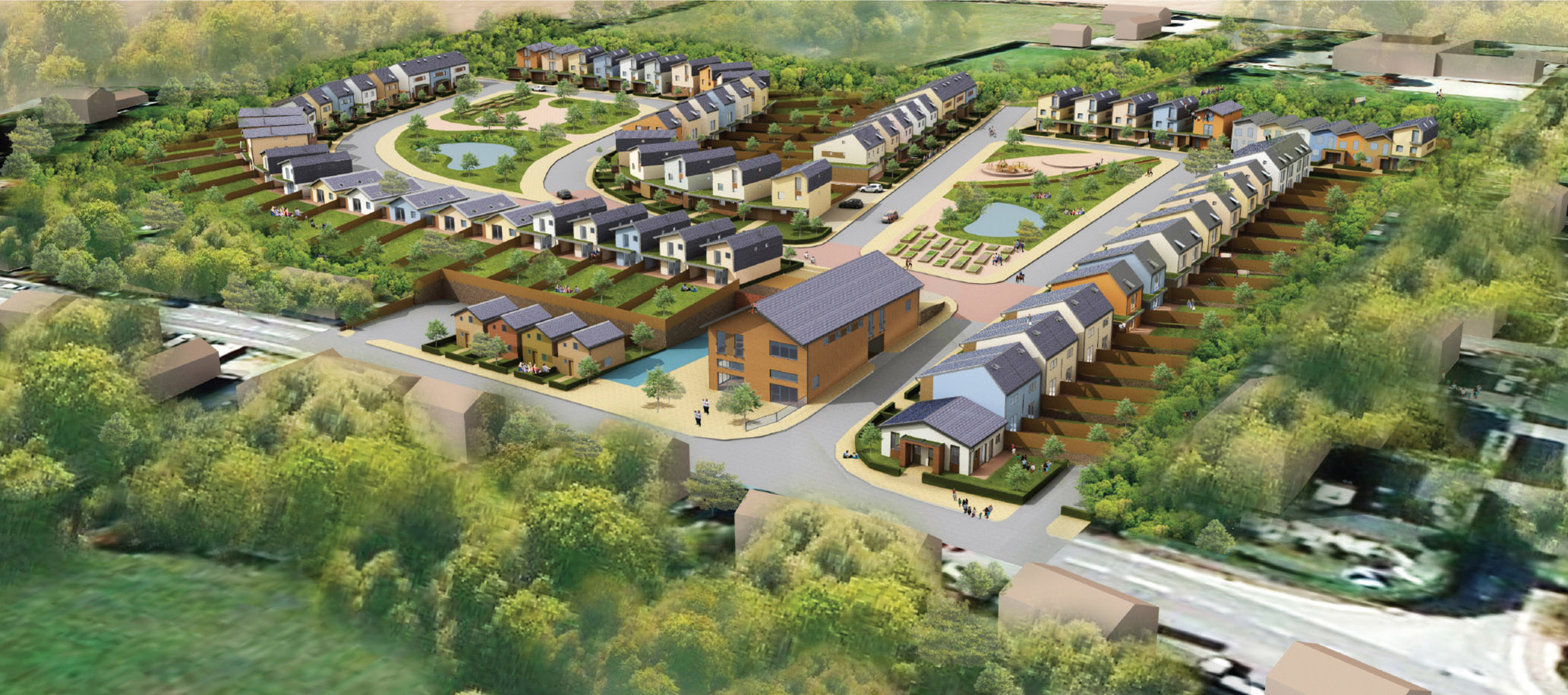
11.3 Aerial view of Newport from the north east.

11.4
Layout enriched with public and private green areas, including around the village green.
The first stage in optimising the design was to conduct a technical and cost analysis of the best available zero-carbon microgeneration technologies. Typically, heat is lost through the building fabric and ventilation, and the need for space heating to compensate for this loss becomes the largest cause of carbon emissions. We investigated the key technologies needed to reduce this and other electric loads, while supplying the residual energy demand via zero-carbon energy generation. These technological solutions were then combined to create a number of
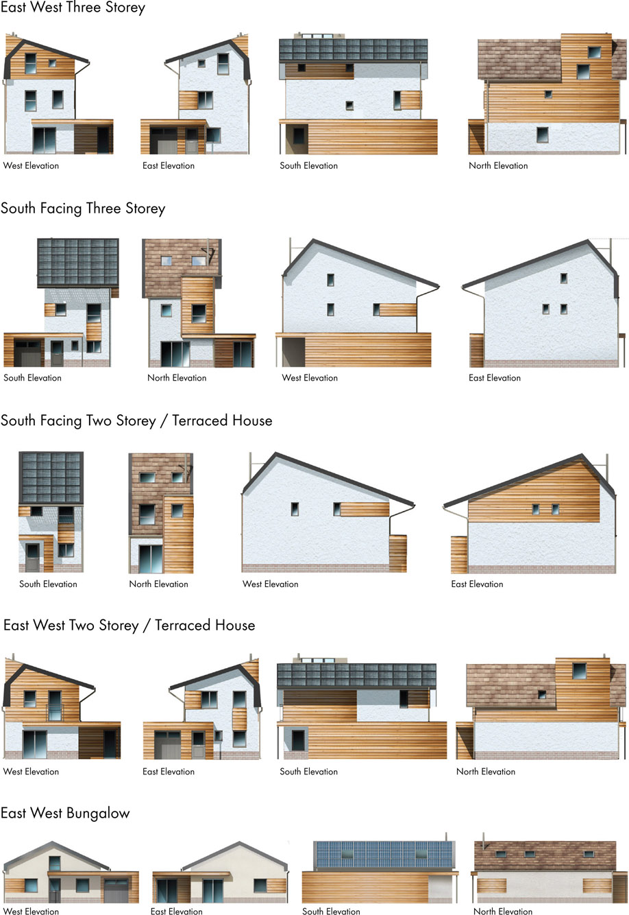
11.5 Zero Bills Home house types.
11.6 The Zero Bills Home floor plan.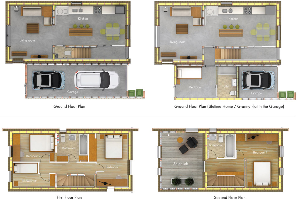
11.7
The Zero Bills Home section view.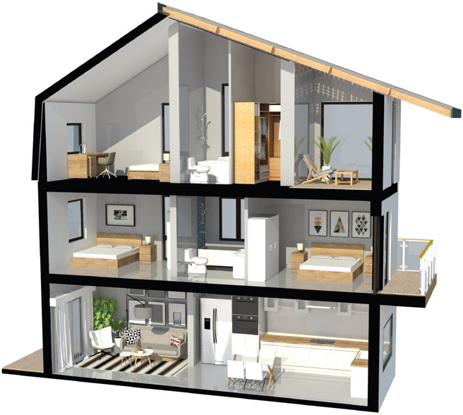
different holistic groupings of building fabric, space, hot water and electrical generation systems.
Our designs were modelled to work out energy losses, energy usage, energy use reduction and energy production outputs. Costs were obtained from manufacturers and distributors for a 100-home development based on the capital cost of construction plus running costs, and these could be offset against savings from reduced consumption and additional income from feed-in of current.
Fixed parameters were applied for space heating demand, using an 18°C set point. Hot water demand was based on five-person occupancy at a rate of 50 litres of hot water/person/day, and the estimated electrical consumption, including lighting energy use, was added. The variable parameters included:
- wall and window U-value
- space-heating consumption
- ventilation-rate energy loss with heat recovery
- heat-recovery efficiency
- heating and hot water system efficiency
- passive solar gains and internal gains
- energy generation by different renewable energy systems
- renewable energy system sizing
- implementation costs
- build costs
- running costs.
We matched each of these against the others to find the best approach to the building fabric, energy-generating mix and running costs. There were varying combinations of PV, air and ground-source heat pumps, passive and mechanical heat-recovery ventilation systems and thermal stores. We also tested how cashflows would come out by adding in FITs (feed-in tariffs)14 income. The saving on energy costs from load reduction and energy generation would bring a further cash benefit. All were calculated using 2014 market rates and mortgage costs. At the end of this process, we got a fair idea how the optimised building would compare to a home built to 2013 Part L Building Regulations (figs 11.6–11.7).
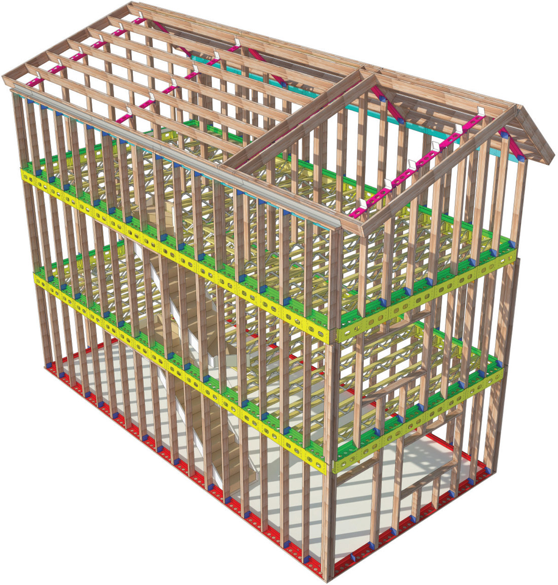
11.8
The timber frame construction system, with floor level beam system allowing flexibility of window and door positions.
The Zero Bills Home construction system
The ‘balloon frame’ was the most common way of building a timber house in the US during the 19th century. It uses lightweight and thinner framing members than traditional wooden construction and the studs in the wall carry an equal distribution of the vertical and compressive loads of the building – hence the rather unexpected borrowing of the word balloon, because the frame carries the same load evenly all over. The Zero Bills Home uses semi-balloon frame construction, with oversized timber. Rigidity is provided by the outer OSB (orientated strand board)15 sheeting, with the upper floors carried by horizontal joists on top of the studs. The oversized studs meant that the building could bear the weight of thicker insulation and other loads, while allowing for thermal mass to be created between the studs. Another benefit of the semi-balloon frame is that it allows the breather membrane and airtightness layer to be dressed in a continuous layer up the wall face. This makes airtightness detailing easier in the upper parts.
To avoid on-site construction work, all the components arrive on-site pre-cut and dimensioned. The Zero Bills Home system frame departs in a significant way from the norm, using a ring beam or lintel at each floor or at roof level, which speeds up and simplifies the framing process. These are made of laser-cut folded steel; a new application of this technology. The framing system based on this hybrid shell is shown in fig. 11.8 (previous page).
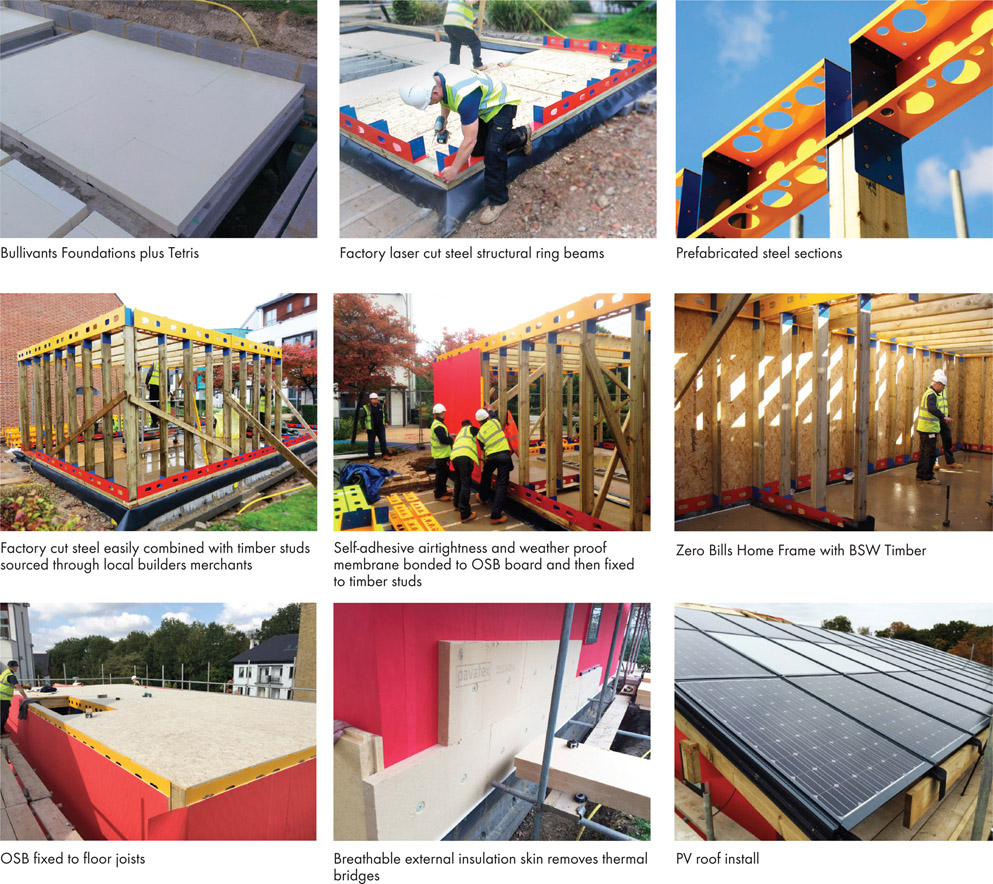
11.9 The Zero Bills Home construction sequence.
Whereas a typical timber frame takes at least three months to order from an off-site factory, you can now order all the components for a ZEDhome from stock. This reduces construction lead-in times and hence loan costs, while minimising the danger of programme slippage. The skills level means that the majority of the labour can be sourced locally, in such a way as to incorporate skills training. Construction quality would be inspected and certified to high standards (fig. 11.9).
Fabric energy performance strategy
The timber frame construction method brings additional benefits. It is easier to adapt the frame dimensions to allow different thicknesses of insulation between the studs, internally and externally. This makes it easier to optimise the energy-reduction and energy-generation strategies. More choices can be made to achieve the best outcomes of cost for the initial build and the lifecycle of the building. Among these choices is to increase the capacity for thermal mass, which in turn enables the inside spaces to perform better, similarly reducing energy inputs and lifecycle costs.
The timber frames are ‘dry construction’ and the less predictable ‘wet trades’ involving concrete, cement and plaster could be avoided, reducing the number of contractors and simplifying the build process. When combined with partial off-site construction and prefabrication of wall panels, we could benefit from ‘just in time’ deliveries and a general speeding up of the process.
Warranty providers like to know that anything they cover will last longer than 60 years. ‘Modern method of construction’ (MMC) is a danger signal to them for this reason, making mortgaging more difficult. For a new home to be mortgageable, the main structural components must last for three generations – which is around 60 years. Almost all traditional homes last far longer – however key fixings or structural brackets in a modern MMC home sometimes only just last this period of time. For example, if a plastic vapour control layer is installed to prevent internal humidity condensing on light-gauge galvanised steel framing, and this has a practical life of 25 years before failure, it cannot be assumed that the structure would not suffer from serious corrosion caused by interstitial condensation occurring well within its 60-year minimum required life expectancy.
The Zero Bills Home uses no vapour control layer and always uses vapour permeable materials throughout its external envelope with careful attention to minimise or avoid cold bridging. This avoids almost all interstitial condensation, and even if any occurred it would be allowed through the ‘breathing wall’ to the ambient external airspace, in much the same way as a Goretex raincoat. No urethane foams or vapour-blocking materials are specified above ground to avoid toxic fire load and condensation occurring at impervious board joints.
As our type of frame avoided MMC, developers should be happy because buyers would not suffer this hassle and expense. National house builders have a reputation of being conservative, but we can offer them cost reduction, straightforward lending and LABC warranty under standard terms, so there should be no barriers to taking up our offer.
Due to its cost effectiveness and inert nature, a mineral wool roll with a Lambda value of 0.037 W/m2K was chosen to insulate between the studs to a thickness of 140 mm. Fossil fuel-derived materials have high embodied carbon, ODPs, CFCs or VOCs, so we left them out of the study. Mineral wool is odourless and doesn’t get wet, so it is also rot-proof and no friend to fungi, mould or bacteria. Mineral wool is also CFC free, HCFC free has a low-ozone depletion and low-environment impact potential. Compared to natural insulation it offered the best trade-off in terms of price and performance at the same U-value.
To super-insulate the building, insulation was added internally and externally to a combined thickness of 335 mm. Externally cork or wood fibre panels can be used, with cork on the inside, since it is one of the most environmentally benign products available. Based on its sequestration over its growing life, cork can be deemed carbon neutral. It is naturally bonded so has zero ODPs, CFCs or VOCs and is technically a waste product. Expanded cork beads are naturally bonded to create the insulation panels offering a Lambda value of 0.038–0.040 W/m2K.
Having three layers of insulation – outside, inside and in-between the studs – meant that low wall U-values could be created to reduce heat loss, since any potential thermal bridges were stopped off.
The ground floor slab was insulated using a high-density polystyrene (EPS) Passive Slab foundation system. We made a concrete ring beam first, rising from a 300 mm permanent form insulation raft of polystyrene (EPS). This method eliminated cold bridging at the wall-floor junction detail, a critical way of reducing heat loss because the cold thermal bridge between the floor and the walls can become a serious means of heat loss when the upper part of the building is so snugly protected. With this precaution in place, we achieved a U-value of 0.1 W/m2K. Details can be seen in fig. 11.10.
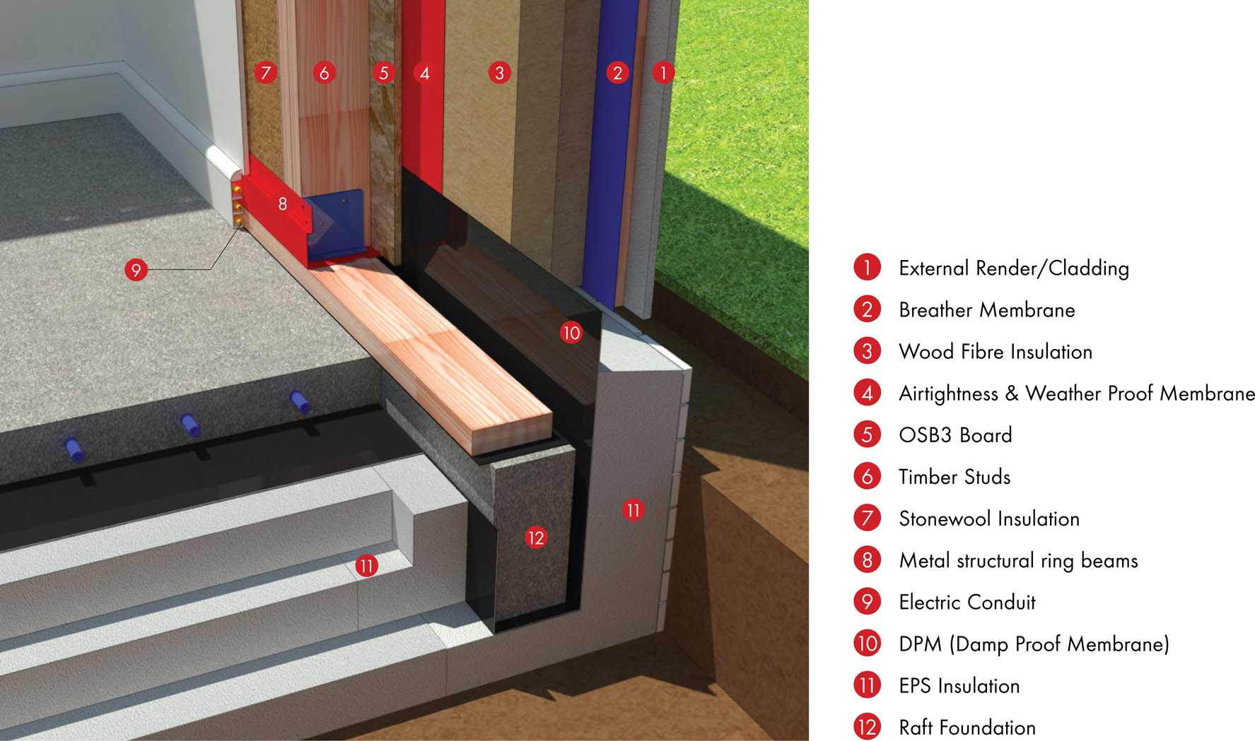
11.10 Section through foundation detail.
A few aspects of this scheme turn out to be frustratingly imperfect, or subject to a pay-off between different benefits. On a constrained site, the very thick walls could mean lower-density housing and/or reduced gross internal space, with the result that fewer homes on a given area of land cuts the developer’s profit.
While the walls of the building were insulated to a U-value of 0.14 W/m2K, it was impossible to get the ground floor slab beyond a U-value of 0.1 W/m2K, owing to the disproportionate cost of reducing the U-value further than 0.14 W/m2K for the walls. This represents the level of insulation that enables us to reduce the heating system to about a fifth of that of an equivalent home.
On a more positive note, a U-value of 0.14 W/m2K still allowed us to design a cost-effective energy system, as the impact on the thermal load did not significantly increase the plant size. For example, a reduction to 0.12 W/m2K would require an additional 100 mm of insulation, but this was not worth the effort because the saving on thermal energy input was small – only 200 kWh per annum. This additional thermal load did not require a larger heating plant to satisfy it, as the peak load only changed from 4.025 kW to 4.107 kW with the reduction in insulation. The increase in the wall thickness was 200 mm on the north–south and 200 mm on the east–west walls when combined, both of which would raise the cost of additional insulation and upset the building footprint/site density ratio.
It was also easier to incorporate additional insulation into the ceiling plane to achieve 0.1 W/m2K more cost-effectively than it was in the walls, thanks to the way the timber beams had to be oversized for the structural load. As ceilings do not affect the gross internal floor area or the plot size on a site master plan, this was not detrimental to density or building footprint size.
Built as described, the ground floor slab was easier to insulate to a U-value of 0.1 W/m2K and an additional benefit was to eliminate the need for external footings and the amount of concrete required. This meant that the concrete only needed to be poured once, making it much cheaper than traditional strip foundations. The cost of the foundation ranged from £5,800 to £15,000, depending on ground condition. The mid-range option of £10,700 was used in this study.
Insulation strategy
Airtightness, provided by the materials and continuity of the airtightness line, is another critical factor in reducing heat loss. At 15 mm, the OSB3 is considered to be airtight if correctly taped and sealed. The detailing of all critical junctions ensures the continuity of the airtightness line, along with the correct taping and sealing around projecting window apertures. The goal for this building was to achieve 1.5 air changes per hour at 50 pascals based on the taped and sealed OSB3 (fig. 11.11).
Energy strategy depends equally on thermal mass. Because timber-framed buildings are lighter in weight they are less effective in this respect.
We would normally hope to exceed 200 kJ/m2K as a measurement of thermal mass and we actually achieved 239 kJ/m2K, which shows that this need not be a problem area.
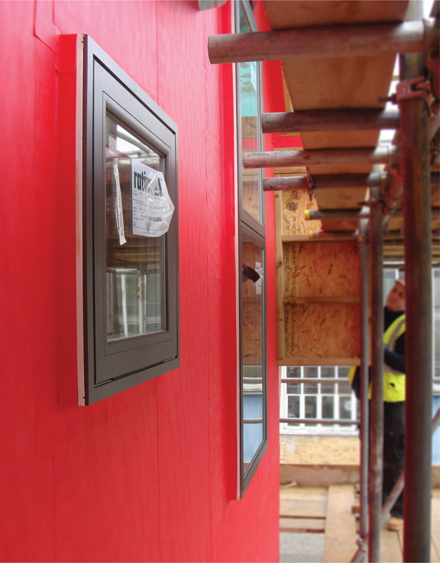
11.11
The BRE house has achieved an airtightness of 1.3 ach @50 pascals text pressure on first test without walls plastered.
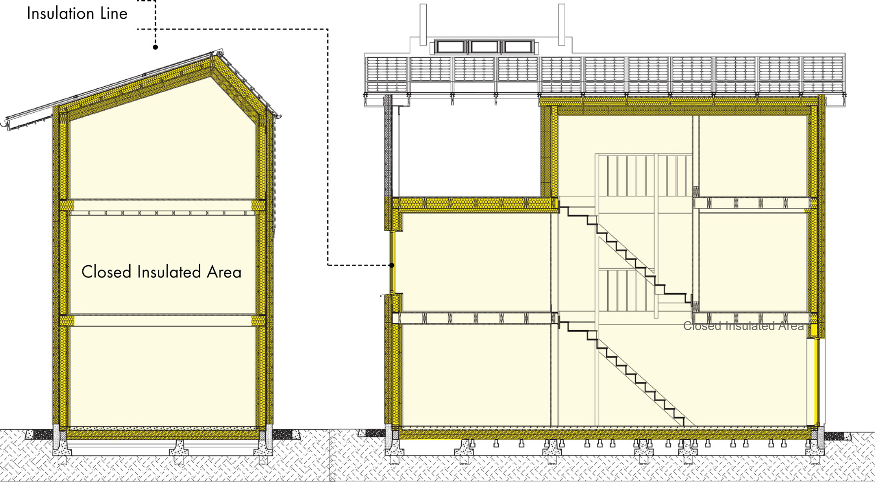
11.12
Thermal envelope strategy on construction drawings.
It was important, too, to choose the right windows, which can be a weak spot for heat loss. Triple glazing helps and thermally broken timber frames avoid further heat loss. Compared to a light-gauge steel-framing stud, timber doesn’t transmit so much heat, so less heat leakage occurs from thermal bridging within the load-bearing frame’s structural studs. A layer of OSB provides racking resistance against near horizontal wind loads and in a Zero Bills Home this is covered in a vapour permeable self-adhesive airtightness barrier. Finally, 150 mm of wood fibre external insulation board is applied to all external surfaces to further minimise thermal bridging (fig. 11.12). Thus equipped with a U-value of 0.9 W/m2k, G-value of 0.51, a frame factor of 0.65 and light transmission of 0.72, these windows played an important part.
Energy systems
Even after all these energy-saving measures, electricity needs to come from somewhere. We installed a 200 L insulated hot water tank and, allowing for some heat loss along the pipework and taking the manufacturer’s data as a guide, we calculated that an allocation of 951 kWh of energy per person was required to meet the hot water load.
These figures have to take seasonal variation into account, including the positive effect of the warm months. Factoring in unregulated loads based on LED lighting and low-energy appliances we achieved a figure of 3,400 kWh per annum for the annual load. The total for the building came out at only 6,058 kWh per annum.
For this level of demand, what is the best way to meet it? The energy system that offered the best balance of costs and usability was based on BIPV according to the ZEDlife standards, meaning that a combination of solar PV, MVHR and a small ASHP could meet the energy loads easily, with heating and hot water reduced by a factor of 3.5 to account for the annual heat pump efficiency. Extra PV and efficient heat pump added to the mix. The PV offered better cost-benefits than the solar thermal and thus although it increased electrical energy demand it also reduced costs in use.
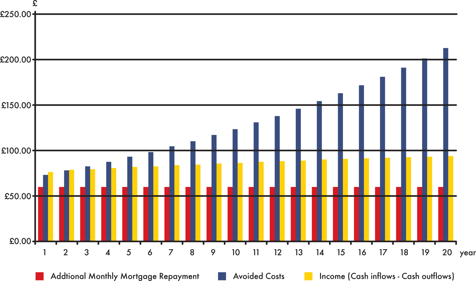
11.13
Monthly cash flows and avoided costs.
To calculate the full building specification, all elements were priced using current data. If the cost of construction and interior finishing (£1,350 and
11.14 Contribution to net monthly benefits from income/cost savings.
11.15
Short-, mid- and long-term viability under different income scenarios.
£1,500 per m2) came out 6–10% above minimum standards, the uplift could be justified through lifecycle cost savings. Figures 11.13–11.15 show the results of the lifecycle cost modelling, showing that consumption and production of energy well outweigh the extra start-up cost quite early in the lifespan of the building.
Figure 11.13 shows the monthly cash flows and costs avoided. The chart demonstrates that the additional monthly mortgage payment is always lower than the income generated from the FITs without having to take into account the avoided costs. It also shows that inflation and fuel price escalation significantly increases the effect of the avoided costs over time, so who wouldn’t choose this future security? The technologies responsible for reducing energy consumption turn out to be as important as the income generated through the BIPV.
In fig. 11.13 we can also see that the running costs are effectively substituted by the increased mortgage cost. If it had been a normal building compliant with the 2013 Part L standards, this money simply would have gone to pay an energy provider, but in this case, the money can be used to pay down the debt on the building instead. A note of caution is needed, however, because although this sounds good, recent policy changes suggest that the FITs payback levels may not be maintained indefinitely.
Positive net benefits can be achieved in both the short and long term, all the same. The positive cash flows achieved with the FITs mechanism give at least a short-term viability shown by positive cash flows over the first 20 years. Using cash inflows alone, it is still possible, as line two in Fig. 11.15 demonstrates, to come out on top through the costs that have been avoided. This means that, even with an increased mortgage payment, the optimised zero-carbon home is more economical to live in than a 2013 Part L building regulations home from the outset. This means that money otherwise destined for energy bills can be switched to increased mortgage costs and still provide a cash benefit. Line three in Fig. 11.15 shows that when the FITs generation tariff is omitted, the model still returns a positive net benefit from year three onwards. While there is a slight deficit in the first three years of the investment, the 17 years of positive cash flow far outweighs this. As such, the Zero Bills Home should be more attractive to the consumer.
Going off-grid: The next stages in a Zero Bills Home
The Zero Bills Home energy strategy and concept set out in the previous parts of this case study have been based on offsetting the residual energy load, after energy-saving strategies have been employed, with solar produced energy (fig. 11.16). While this works well for the annual energy balances the reduced load is met in three ways:
- By directly using solar energy from the PV array. This requires appliance loads to be matched with generating times from the array. It is hard to match the demand to the supply, but some small changes in behaviour go some way to closing the gap. The limitations of both, however, mean that to keep increasing the size of the array does not on its own solve the problem.
- An LiFePO4 battery to store some of the excess energy produced by the PV is a way of getting round this, while reducing the amount of grid energy imported (fig. 11.17).
-
In a country with low winter temperatures, the system will not generate enough to allow users to go off-grid. When the system does not generate sufficient energy during times of low production, residual loads must be topped up from other renewable energy sources. If the grid is not available, then micro wind turbines or small biogas-powered generators may be required.
The length of time during which a house must draw energy is actually surprisingly small. While it is true that renewables do not produce a constant level of supply, as we go on to explain, evidence shows how houses can be designed to maximise ‘off-grid’ time without their residents having to change their lifestyle to an inconvenient extent. This means that the centralised energy produced and distributed via the National Grid could be scaled down, and that the commonly made claim that nuclear power stations are needed to ‘keep the lights on’ is dangerously misleading.
PV array sizing
Getting the right size for an array and battery system requires balancing the interplay between daylight usage, total usage, generation and cost. There is a range of activities requiring electric power, such as heating up water, using it for washing clothes and dishes, that if done in daylight hours can be powered directly from PV. That leaves other things, such as part of the daily cycle of space heating, ventilation, fan and pump loads and fridge-freezer loads, that have to continue round the clock.
The Zero Bills Home was originally designed to be cost-neutral to any owner-occupier who used the FITs tariff to offset additional payback costs incurred by an increased mortgage. If you can create a building that produces 8,033 kWh of PV-generated energy with an annual demand of only 4477 kWh, then the excess can be exported to the grid and made available for electric transportation, among other uses. The array is large enough to cover, at least partially, the largest deficits in winter peak loads and tough production.

11.16
Inside the solar loft.
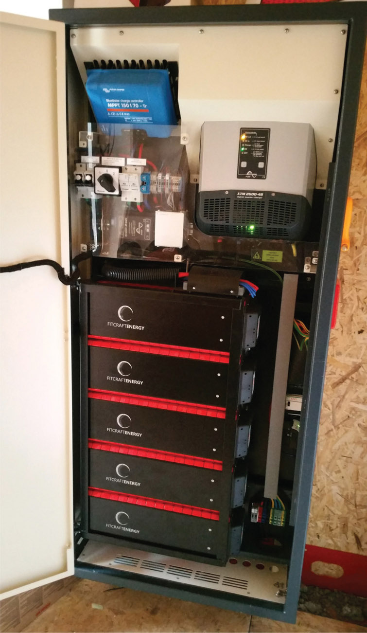
11.17
The Zero Bills Home’s 7.5 kWh battery inverter.
We need to think about the right size for these arrays in the coming years, because an array sized to offset winter load is massively oversized for summer demand. If the house is fully electric, then daylight consumption should equate roughly to between 30% and 40% of the PV-produced energy taken for use by the home itself. This means that between 60% and 70% is available for direct export back to the grid. Considered in this way, the grid is essentially being used as a battery to store excess production and allowing it to be drawn back during hours of production deficits. It is a neat system, but the money equation relies on the FITs payments, which are shrinking. This means we need to look at further opportunities to reduce cost and maximise returns. Additionally, flowing surplus energy into the grid tends to happen when demand is at its lowest, which creates problems because of the ageing UK grid infrastructure, when many network operators are claiming to be close to the limits of what the grid can accept. The answer to all these issues must lie in energy storage by means of the new batteries.
Determining the load and self-consumption rates
Assuming that many people may not wish to make changes to their lifestyle in order to reduce energy consumption, we have calculated what savings they could make without trying too hard. Loads such as hot water can be relatively easily switched if showers and baths are taken in the morning to allow the tank to recharge while the array is producing. Similarly, dishwashing, clothes washing and drying could also be switched to daytime hours with relatively little upheaval. If we can assume this level of active participation, the energy loads can be modelled, based on the average PV energy production, during sunshine hours.
The result is a balance between usage during daylight hours set against total usage and the cost of generation, and from this we can work out how much battery capacity would be needed. These small but significant LiFePO4 batteries, with their lifetime of 5,000 charge cycles, are the key. Their BMS (battery management system) controls allow them to charge and discharge at the same time.
This system can remove around 78% of the building load from the grid, with 80% depth of discharge, using a 7.5 kWh storage capacity. In this way, the battery system effectively takes away the familiar problem that solar power comes and goes with the sun. If we are going to manage with a reduced capacity grid, this is important. The results show that the building requires 80% less grid electricity than a building without the PV array. Energy transmitted through the grid for the building (import plus export) is reduced by 57%, so if this technique is replicated across all new builds, the amount of grid power needed from all such new housing would be 80% less, compared to a ‘fabric-first’ approach.
The conclusion should be obvious – fabric first isn’t going to solve the critical problems. A system based on battery storage wins hands down and makes it realistic to imagine a reduced-capacity grid without everybody sitting in the cold and dark in their homes. Building any new centralised power plants other than those relying on renewables is not a question we shall need to agonise over any more.
If you are thinking that there are some issues with the problem months of December and January, months when demand far outstrips production from the PV array, we would answer that the negative balance can be offset with the addition of larger communal-scale wind farms, biomass or pyrolysis.
Hastings Zero Bills Home development
Overlooking Hastings’ Old Town to the east, and Hastings and St Leonards to the west, Hastings Castle was built by William the Conqueror shortly after the invasion of 1066. The completion of five state- of-the-art eco homes directly opposite the castle marks the 950th anniversary of the Norman conquest (figs 11.18–11.19).
ZEDfactory was appointed in 2014 by a local builder and landowner who had assembled a small group of friends and local residents interested in funding their own new-build eco homes. Since the site is in the Hastings Castle Conservation Area, a number of proposals had been rejected over the years as inappropriate. A breakthrough came in 2015, when full permission was granted for a revised scheme that proposed a highly energy-efficient terrace of zero-carbon dwellings.
The five timber-frame homes, arranged as a terrace, are constructed on a raft foundation that was
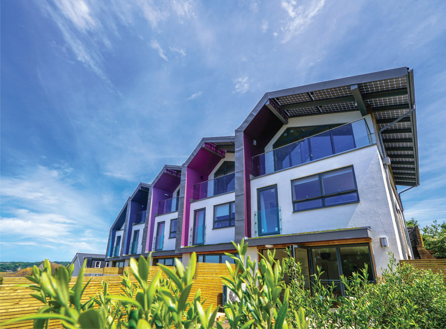
11.18 Zero Bills Homes on-site at Hastings, UK.
11.19
Front view.
built for a previously abandoned scheme, and stand three storeys high (figs 11.20–11.21). Living rooms and kitchens are on the ground floor, with living spaces opening onto garden terraces. Three bedrooms are fitted into the floor above. The top floor, with magnificent vistas across the coastline, makes a flexible second living space which could be used as a home office, games room or second living room, opening onto a small roof terrace with some of the best views in town (fig. 11.22).
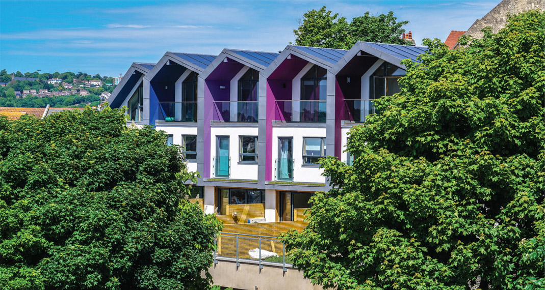
11.20 View from Hastings Castle.
11.21
Public pedestrian street.
The superstructure of the homes is made from a prefabricated timber frame panel system. This is externally insulated with 120 mm of wood fibre, helping to eliminate thermal bridges across the structure. The insulation is protected with a breathable lime render, or over-clad with locally grown sweet chestnut timber boarding. This combination of vapour permeable materials ensures that the structural timber frame can breathe – leading to a healthier and longer-lasting building.
The grid-connected ZEDroof (PV) produces enough electricity to meet the needs of each home, with large overhangs to maximise the electrical output while protecting the walls from the elements.

11.22 Top-floor studio’s sea view.
Heating and ventilation to each home is delivered by a highly efficient ASHP, with combined MVHR (Nilan Compact P). This combined system draws heat out of the warm exhaust air and uses it for preheating the fresh incoming air, while also increasing the efficiency of the heat pump in producing hot water. Heat is circulated around the homes with underfloor heating coils.