6
Digital Fabrication
Bilal Ghalib doesn’t do handshakes, just hugs. The first time I met Bilal, at the first Maker Startup Weekend (a weekend-long making event at TechShop in San Francisco), he came up and gave me a big squeeze.
We had traded a few emails and a brief phone call in the days prior, but we had never met in person. I was organizing the event and was introduced to Bilal as someone who might be a good candidate to teach the 3D printing class we were offering to participants. He seemed like a nice, gregarious guy, but I was still a little shocked when he showed up with rainbow-dyed hair and wearing a bright purple blazer. As it turned out, Bilal’s outgoing and inimitable style made him the perfect person to teach 3D printing—instantly disarming the nerves of beginners like me.
It was perfect timing for Bilal. He was on the tail end of his “Pocket Factory” tour, a road trip around the country with his best friend Alex Hornstein and a MakerBot Thing-o-Matic 3D printer in the back of their Toyota Prius. The trip was an experiment. After spending time at MIT, Bilal and Alex had seen and imagined the potential of desktop manufacturing, and they were curious to find out what the technology meant outside the media lab and in the hands of everyday folks. They drove across the country, stopping everywhere they could: schools, museums, hackerspaces, and even supermarket parking lots. They talked to anyone who was interested. And they experimented, attempting to understand what it meant to have a micro-factory in the trunk of their car.
At first, they tried selling the parts that they printed, fancying themselves a tiny, portable store. That didn’t work very well. They found that people didn’t value the small plastic trinkets they were creating. Then, they tried selling customized products for the “customers” they met, letting the potential customers modify and alter designs before they were printed. That wasn’t profitable, either. By the end of the trip, they realized that the best way to earn money with a desktop 3D printer (and thus keep gas in the tank for their adventure) was to teach classes on how to use the device.
The final stop of the Pocket Factory tour was San Francisco and, coincidentally, our Maker Startup Weekend. I was a few months into the Zero to Maker journey at that point, but I still hadn’t had the chance to play with a 3D printer. The MakerBot at TechShop had been out of commission since I began taking classes there. Now, with Bilal here to teach a class, and his 3D printer under his arm, I would finally get the chance to try it.
After months of being on the road and explaining 3D printing to people who had never heard of the concept, Bilal knew exactly where to start. He began with the analogy to regular inkjet printing. He explained that 3D printing was similar, except that instead of putting ink to paper, the machine extruded a thin layer of plastic, and then another layer on top of that, slowly building up a three-dimensional figure. He understood the challenge of thinking (and designing) spatially for beginners like me. Instead of having us work with 3D models right off the bat, he encouraged us to start with a 2D outline, like our name, and extrude it, pulling the design into three-dimensional space. His explanation and teaching style were perfect for the crowd of newbies. He wasn’t just explaining how to work the machine; he was teaching us how to wrap our minds around the new design possibilities. He continued his lecture on extrapolating 2D familiarity to include shapes, and eventually showed us how to merge shapes to create more complex 3D models, as shown in Figure 6-1.
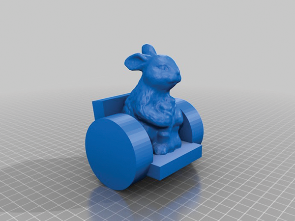
Figure 6-1: One of Bilal’s go-to prints is the “Bunny Chair.”
I was excited to try my first print. I used Autodesk 123D (more on this later in the chapter) to mock up a simple, box-like container for the OpenROV. I was hoping to create an easy way to adjust the ballast of the device on the fly. Then I sat down next to the MakerBot and pulled up the ReplicatorG software (the software that runs the printer). I adjusted the size of my design, scaling it down after reevaluating my original shape, and then clicked Print. The machine began to buzz, and my anticipation started to build. My confidence and excitement—I was creating a physical, tangible object from digital bits!—grew with every layer of plastic that was laid down. The first attempt wasn’t very good; it was disappointing, actually. I ended up stopping it mid-print after the part lifted off the build platform. The second time was the charm.
I carried the tiny plastic object around, showing anyone who would pay attention. Nobody cared. For anyone who had 3D printed before, my creation was nothing impressive. For anyone who hadn’t had the experience, it seemed equally uninteresting. The actual object wasn’t the point, though. This experience was my first taste of 3D printing and the uniquely intriguing power of bringing digital imaginations into the real world. It’s impossible to play with one of these devices and not have your mind wander into thinking that, pretty soon, everyone will want to experience this act of creation.
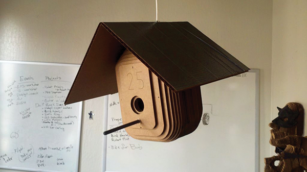
In my opinion, it’s the personally empowering act of creativity that is driving the maker movement. It’s just plain fun to do this stuff (see Figure 6-2 for an example)! But with a slightly broader perspective, it’s also possible to extrapolate the impact of ubiquitous digital fabrication and the effect that could have on manufacturing and the economy.
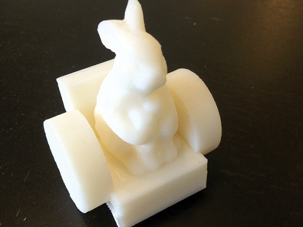
Figure 6-2: Bilal’s Bunny Chair becomes a real thing. You can find the design on Thingiverse (thingiverse.com/thing:18512).
It Starts with Digital Design
The best theory on where this is going and what it means is packaged in Chris Anderson’s Makers. Digital fabrication coupled with the democratized distribution channels on the Internet (e.g., Kickstarter or Etsy) level the manufacturing playing field. In the same way that the web made it possible for anyone to create and share media (movies, music, and books), the barrier for micro-manufacturers is essentially eliminated. Suddenly, we all have pocket factories.
It’s your turn to create. But first, the rules and tools…
Digital fabrication starts with a digital design. This was a huge worry for me. I had heard about and seen CAD programs before, and I had watched as designers and architects used them to create elaborate and complicated designs like motorcycles or buildings. I worried that I would need another degree before I could find any use for that skill. But a few weeks into my journey, I realized it was an unavoidable obstacle if I wanted to play with the digital tools. Luckily, Jesse Harrington Au was there to guide me. He is a lifelong maker, but his story and way of teaching were a perfect fit for my learning style.
At 14 years old, Jesse wasn’t thinking about CAD. Like a lot of kids his age, he was thinking about skateboarding. In particular, he was wondering how he could build a halfpipe—a large U-shaped ramp—in his backyard in upstate New York. His parents had finally given him the go-ahead—on the condition that he build the structure himself.
Before he could start building, though, he needed a plan. He wanted to visualize his creation, so he started designing his halfpipe in programs like Autodesk 3ds Max and Adobe Illustrator, programs he had become familiar with through his interest in animation. Once he had the design, he was able to begin construction. Jesse worried about how he would bend the plywood to fit the curved design he had made on the screen, but as soon as he started, he found the material to be as malleable as he needed. A few weeks and a hundred dollars later, Jesse had the halfpipe of his dreams. More important, he had been bitten by the design bug.
His projects grew in complexity, from designing solar heating devices with his dad and brother to creating complex art projects to fill large, empty rooms. Jesse was finding all sorts of uses for his burgeoning CAD skills. He was also developing a joy of sharing the maker skills he was learning. During college, he had a job working at a daycare for kindergartners, and in an effort to get the kids building and making, he organized an activity for the kids to build their own guitars, drums, and horns. None of the parents or other daycare employees thought the kids would be able to hang in there with Jesse’s plan, but by the end of it they had created their own band and were performing concerts for their parents. He also worked part time teaching CAD to other students at Rochester Institute of Technology. Jesse’s diverse maker career eventually brought him out to San Francisco to work for the Exploratorium, building exhibits for the children’s museum.
When I met him, Jesse was working as Autodesk’s “Maker Advocate.” He spent most of his time in makerspaces around the country, working with makers (especially new ones) to build their CAD skills and incorporate digital design into their maker toolbox. In the past few years alone, he’s taught and assisted over a thousand new makers as they wade into digital fabrication. That’s how we met. Jesse was teaching classes in Autodesk Inventor, Autodesk’s product design CAD program, at TechShop in San Francisco. The class is a complete crash course; Jesse explained to me that he’d squeezed the 15-week course he taught in college into a curriculum that teaches the material in three hours. I pressed him on how he was able to do it, and he attributed it to the eager curiosity of makers:
If you give passionate people the tools and time to play—learning just enough to play—then they’ll get it every time.
Here are some other tips from Jesse’s experience:
- Ask yourself: Do you really need CAD? CAD is the first step in the digital fabrication process, but it’s important to remember that using CAD isn’t always the right solution or option. It’s great when you have something that’s an interesting or odd shape, such as a curve that needs to be exact. It’s also necessary for designs that you want to repeat or manufacture. But if you’re rapid prototyping and you just want to see if something will work, the best option may be just to use a table saw or another analog tool to quickly mock up the prototype.
- Be patient; know your options. There are a lot of CAD programs out there for makers, even new makers. Over the past few years, a slew of new options have become available that are especially suited to new makers. It’s worth trying a few of them to see which one feels the most comfortable.
- TinkerCad A great option for beginners (and also kids—more on this in Chapter 9, “Making More Makers”). This browser-based program is incredibly easy to get started with, doesn’t require you to download or install any software, and makes it simple to export to a 3D printer or printing service. It’s great for primitive shapes but trickier for more complex designs.
- SketchUp Make This is the free version of the powerful CAD program called SketchUp Pro. It’s a great beginners’ platform, too, and there are tons of free videos that teach you how to use it.
- Autodesk Fusion 360 Probably the most popular 3D all-in-one modeling package as of this writing, Fusion 360 is optimized for product engineering and manufacturability.
- Rhinoceros Also known as Rhino or Rhino3D, this commercial package models free-form surfaces and curves as opposed to polygons. It’s great for prototyping but may have a stiff learning curve for beginners.
- OpenSCAD This free, open source application is purely script based (it does not feature an interactive 3D modeling interface). If you are comfortable with programming or markup languages, you will love its ability to precisely and efficiently create parametric models.
- Onshape If you are working in a group setting, this cloud-based CAD program features a well-designed interface and real-time collaboration. It’s a good choice for schools and colleges.
- Autodesk Inventor If you’re looking to make a career out of your design work, or you want to manufacture your idea, you may want to go right into the pro tools. Inventor is the CAD tool of choice at TechShop and beyond. Online training classes are available online on the Autodesk University site.
- LinkedIn Learning It’s not a CAD program, but a trove of CAD and general design wisdom. They have courses for many different programs serving everyone from beginners to experts. I have this site bookmarked, and it’s my first stop when I’m looking for online design instruction.
- What are you making? What’s the output? Are you making something mechanical? Or is it just a replica of a character? If it’s something that will move, the precision of CAD design can be critical because you need those exact measurements. If it’s a model of your own head, CAD won’t be as helpful. You’d be much better off using a laser scanning or photogrammetry device that can, essentially, take a 3D picture and translate it into digital bits.
- Along the same lines, your approach also depends on your intended output for the digital design. Will it be 3D printed? Is it going to be used for manufacturing tooling? Thinking through the intended use will help identify the most effective mode of design.
- Don’t re-create the wheel! Part of learning CAD is being aware of the vast libraries of designs that are freely available on the Internet. You don’t need to create every part or model from scratch. Many of your designs can come from modifying an existing model or assembling a set of parts. Here are some resources for finding existing designs:
- Thingiverse (thingiverse.com) This website was started by the MakerBot team to share the designs of desktop 3D printer users. Thingiverse has evolved into one of the largest repositories of 3D designs, where you’ll find everything from iPhone cases to remote-control car wheels. Thingiverse tends to slant toward designs that work best for the desktop 3D printers.
- GrabCAD (grabcad.com) GrabCAD boasts over 2 million files, ranging from motor design to mechanical horses. The GrabCAD library is suited to a community of mechanical engineers, and the designs reflect a higher degree of sophistication and precision.
- 3D ContentCentral (3dcontentcentral.com) Like GrabCAD, 3DContentCentral is a repository for thousands of predesigned files that you can use to build your model.
- McMaster-Carr (mcmaster.com) McMaster-Carr is the hardware store for the Internet. It has over 500,000 products—every screw, fastener, or fitting you could imagine. In addition, it has a CAD file for nearly every product. Know this before you try to redesign a screw or bolt!
- Inventables (inventables.com) In addition to the thousands of products and materials for designers, Inventables has a collection of projects that include CAD files, a list of the materials required, video instructions, and a way to ask the designer a question. Most of the projects are made using tools such as laser cutters, computer numerical control (CNC) mills, and 3D printers.
- It’s a language! As with any other language, learning CAD is going to take some time. The only way to get better with CAD is to practice. Luckily, it’s easier than ever to get started, and it will certainly be one of the most useful skills of the twenty-first century.
3D Scanning
Just as the CAD tools race to become cheaper and easier to use, 3D scanners and photogrammetry tools are also becoming more affordable (even free) and increasingly functional. These tools use lasers or a series of photographs to take what amounts to a 3D photograph of an object or scene, which can then be manipulated and modified as a digital design.
My first experience with 3D scanning came with the NextEngine 3D Scanning class at TechShop. The NextEngine uses lasers, a camera, and a rotating platform to scan objects into a digital model. At first, I was confused as to how and why this type of tool would be useful. It seemed like a novelty and only good for small trinkets. It wasn’t until a classmate showed me a sea shell he had found and wanted to digitize that I began to realize the usefulness of the tool. He explained to me that he had tried to re-create the shape in CAD but wasn’t able to do it. Scanning was the only way to duplicate the organic shape. With a series of photographs taken from multiple perspectives around an object, the app is able to model that object in digital form. I started where most people do: trying to create a model of my head, as shown in Figure 6-3.

Figure 6-3: A model of my head
After seeing how easy it was, I immediately began to wonder if we could use this technology underwater with our OpenROV cameras. I had visions of using OpenROV videos to create 3D models of coral reefs, with the hope that easy-to-create 3D renderings would make it easier to visualize their health over time.
But first I had to see if the technique could work underwater. Unable to find any examples online, Zack and I decided to experiment with it ourselves. We ended up taking a daylong excursion to the Aquarium of the Bay in San Francisco, pushing the boundaries of acceptable “touch pool” behavior by taking numerous photographs of starfish underwater. The results were surprisingly good.1
Most important, that was our first attempt. When I asked the Autodesk team for other underwater photogrammetry examples, they didn’t know of any. I found scientific research papers that had shown it was possible. At the time, two guys with almost no experience, an underwater camera, and free software could test the limits of the shifting digital/physical boundaries. We published a short blog post about our experiment on the OpenROV website and let it go. But our community kept the idea alive. We ended up seeing reports and models from groups all over the world—people who had come across our work or had stumbled into the same idea. Taking it to the extreme, one team of divers used the same Autodesk software to create finely detailed models of coral reefs. Their initial success inspired the formation of a nonprofit organization called The Hydrous. This organization is now on a mission to make 3D models of vulnerable reefs around the world, helping in the monitoring and protection of these vulnerable ecosystems.
This type of exciting application finding is happening beyond the oceans, too. As cameras get cheaper and more prevalent, this type of model-making is continuing to find new applications—especially with drones and aerial photography. In the past few years, dozens of new companies and products, like Pix4D and OpenDroneMap, have sprung up to capture this interest and find economic application. The physical world is getting digitized faster than anyone thought possible.
3D Printing
OK, so you’ve got a digital design. What now?
One of the most exciting options is to print that design using a 3D printer. At a broad level, it’s as easy as just clicking Print and waiting for your design to appear.
Additive manufacturing, another name for 3D printing, isn’t just one technology. Several different processes are classified as additive manufacturing. The most common technique for desktop variety 3D printers is fused deposition modeling (FDM), which pushes heated filament through an extruder down onto a build platform, creating a thin layer of plastic that can be built up. Other additive manufacturing technologies, stereolithography (SLA) and selective laser sintering (SLS), use lights or lasers to cure liquid resins or powder to form the desired 3D model.
The promise of desktop 3D printing is that we’ll be able to print many of our household items through one machine that sits on our desks. The reality, of course, is much different. It’s not the panacea that some media articles have made it out to be, but it’s also not just another toy. It’s somewhere in the middle. Only time will tell exactly how people will integrate these machines into their lives. Regardless of its eventual impact, the magic of desktop 3D printing is an important part of the new maker experience.
3D printing isn’t new—it’s been around for decades. Inside university research labs and the R&D departments of multinational corporations, the technology has been used to create prototypes of concepts, products, and ideas. The recent 3D printing boom is less of a technological advancement and more an accessibility revolution. Expiring patents and fierce competition are creating a surplus of consumer options. And it’s moving quickly.
At the World Maker Faire in 2012, there were over 50 different models of low-cost 3D printers, each one slightly different from the next. They vary in shape and size, cost and competency. Getting started with 3D printing has never been easier or more accessible, but it’s also never been more confusing. Where do you start? How should you approach this world?
If you’re interested in using a 3D printer or you want to build your own, Make: magazine’s annual guide to 3D printers is a good place to look for up-to-date advice. Maker Media also published a book by Liza Wallach Kloski and Nick Kloski called Getting Started with 3D Printing (2016) that provides an overview of the hardware, software, and services. If you’re not sure what you would do with a 3D printer, I suggest playing around with one first, by either using one at your local hackerspace or trying out one of the many 3D printing services that will ship your prints to you, such as Shapeways or Ponoko. Experiment before you invest.
Figure 6-4: A Make: Labs annual 3D printer “shootout” (photo by Hep Svada; used by permission)
Laser Cutter
“And that’s just the beginning—there are all types of materials that work with the laser cutter. In addition to cardboard and paper, you can etch glass, cut acrylic, and engrave leather. You can even laser etch onto a chocolate bar,” said Zack, my maker sherpa and TechShop Dream Coach. He was also today’s Laser Cutting substitute teacher.
“Wait a second—chocolate, seriously?” I asked in disbelief. “Doesn’t the laser melt it?”
“Nope, it works great. I used the laser cutter to engrave a picture and a poem on a chocolate bar last year for Valentine’s Day. My girlfriend assumed I had organized a custom mold at the Ghirardelli factory, but it was only five minutes of laser cutting time after work one day.” Zack paused, then continued: “I actually have a bar of chocolate in the freezer—we can try it out right now.”
Next thing you know, everyone in the course was eating a piece of chocolate that they had just laser-cut their name into.
One of my main assumptions starting out on this journey was that I wouldn’t be able to make anything cool right away. I thought I’d be exposed to different tools and processes, but I expected it would take years of practice and many mistakes before I could do anything useful. The Laser Cutting course at TechShop, shown in Figure 6-5, totally blew that assumption out of the water.
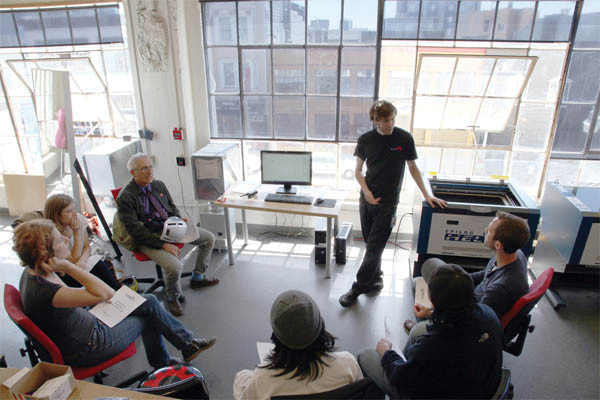
Figure 6-5: The Laser Cutting course
It started off just how you would expect: basic safety information and an overview of the machine (on/off, cleaning the lens, orientation, etc.), but Zack quickly let us loose to try both raster cutting (used for engraving/etching) and vector cutting (used for clean cuts through material) for ourselves. It was such an easy process to learn that I was a little embarrassed that I hadn’t attempted it sooner. I think I harbored a bizarre fear that I needed more CAD experience or some other technical know-how, which is not the case at all. The machine runs from Adobe Illustrator or CorelDRAW. It’s as easy as typing, drawing, or uploading an image you want to use and sending a print job (with a few settings tweaks) to the laser cutter.
Aside from the general ease of use, I was surprised at how many ideas for using the laser cutter were pouring into my head. I could use it to personalize my wallet, create a mold for a ceramics project I was envisioning, or repeat Zack’s chocolate etching. The laser cutting experience was also valuable for our OpenROV project. We had recently redesigned the frame of the ROV to be cut from a single sheet (24 × 18 inches) of 1/4-inch-thick acrylic. After a quick heat bend of the main section, the rest of the pieces snapped into place. Using a single sheet (as opposed to multiple materials, connected with adhesives and fasteners) cuts the cost of the ROV dramatically (which is the main goal of the project) and makes it fast and easy to reproduce (the other main goal). After taking a two-hour course, I could easily contribute to creating OpenROV structures.
I’m not alone in my admiration and appreciation for the laser cutter. In Makers, Chris Anderson called the laser cutter “the real workhorse of the Maker Movement” because it’s the one that everyone uses first and most often. TechShop staff (and others) refer to it as the “gateway drug” to digital fabrication. It’s how Bilal initially became involved with the maker movement, breaking into the local art school to create stencils for his printing business. After you make something with a laser cutter, it’s hard to go back.
Getting Creative with 2D Design
There are several advantages to using the 2D digital fabrication tools, such as laser cutters, in lieu of the sexier 3D printing methods. Most notably, the 2D fab tools are much faster. If you plan to do any kind of small batch production run—from 20 to 1,000—you’ll care a lot about speed. It’s possible to use a laser cutter for this type of micro-manufacturing (when you get into the 1,000+ range of production runs, you’ll probably need to develop a broader manufacturing strategy). To give you an example of the time savings, laser cutting an entire OpenROV shell (the acrylic structure) takes less than 20 minutes. In contrast, it would take almost a full day on a 3D printer. And at this point, the desktop 3D printers aren’t fit for production tolerances. With the laser cutters, we get precision cuts every time—good enough for our OpenROV kits. With desktop 3D printers, it’s not nearly as consistent.
However, don’t let 2D tools limit you to 2D designs. There are a number of strategies to extend the utility of the laser cutters and CNC mill machines into the third dimension:
- Origami I’m continually blown away by the creative ways I see makers folding and bending their designs into more useful shapes. We spent a lot of time trying to arrange perpendicular pieces of acrylic for the outer shell of our OpenROV. One day, while we were working at TechShop, another member suggested we use the strip heater to bend one piece of acrylic instead of trying to attach two pieces. Eric and I looked at each other with bewilderment. We had never even seen the strip heater in the corner of the shop, and we had never thought about bending our design. It worked perfectly. It was cheaper and easier, it looked better, and it gave the ROV more structural integrity.
- I’ve seen an entire origami kayak cut from one piece of corrugated plastic board (more on this in Chapter 7, “One to One Thousand”). With a little imagination, a series of bends and folds can go a long way.
- Stacking Anything that can’t be accomplished with folds can likely be figured out through assembly. You don’t need to be an experienced mechanical engineer or designer to use this strategy. Slicer for Autodesk Fusion 360 automatically dissects a 3D model into 2D shapes marked for assembly and ready for the CNC machine of your choice.
- Boxes and hinges The craft of joinery is nothing new, especially among the Japanese. Even though Wikipedia defines the terms “joiner” and “joinery” as being obsolete in the United States, the lesson of attaching wood without nails and screws is having quite a revival in the form of augmenting CNC’ed or laser-cut structures. As many makers are learning, clever arrangements can go a long way. In fact, the entire internal structure of OpenROV is actually all 1/4-inch acrylic plastic elegantly snapped together.
- Make: magazine writer Sean Michael Ragan has assembled an exhaustive resource at http://bit.ly/166hmdQ that points out some of his favorite methods, shown in Figure 6-6.
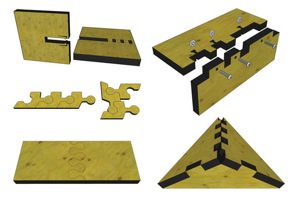
Figure 6-6: Joinery (photo by Sean Michael Ragan)
Digital Fabrication Is Not Just 3D Printing
3D printing grabs all the headlines, but as many makers will tell you, 3D printing is a small part of the digital fabrication revolution. When Neil Gershenfeld first started the fab lab project, he described a list of tools—laser cutters, CNC mills, vinyl cutters, and tools to program microcontrollers—that could create almost anything but also completely replace themselves. 3D printers weren’t even a part of that original tool list. To reiterate his initial hypothesis and to address the growing media attention given to 3D printing, Gershenfeld commented at the Science of Digital Fabrication conference at MIT in 2013 (http://bit.ly/17H6h5I) that the 3D printing hype is “like telling chefs in the 1960s that microwave ovens are the future of cooking.”
It’s a very limited view of what’s actually happening.
Admittedly, I didn’t understand the true potential of digital fabrication until I was several months into the journey. The 3D printer caught my attention with its novelty. The laser cutter surprised me with its ease of use. But it wasn’t until I first used a CNC mill machine during a ShopBot class at TechShop that I truly grasped what was going on.
The ShopBot class was a long time coming. In addition to the hands-on classes and experiences, I was learning the software side of things. As part of the membership package, TechShop offered a list of CAD classes based on Autodesk software. But there were also CNC courses that took place in the computer lab, such as “CAD to CAM,” where I learned about the software used to translate the digital designs into the programming language for CNC machines and G-code. Even though I didn’t have a clue what those letters meant, or what I was going to use these techniques for, everyone kept reiterating their importance. They were right.
Something clicked during that ShopBot class. I realized how, with some combinatorial creativity, you could take just about any idea from digital bits on a computer screen to something real and tangible. Whether it was 3D printing, laser cutting, or CNC milling, there was almost always a way to bring those digital files to life (and then to share them). More important, I realized how accessible all these tools actually were. I mean, I was actually using them! Sure, I had been taking classes for the past few months. But that was it. No engineering degree. No garage tinkering childhood. Nothing. But here I was, with the power of a micro-manufacturing operation at the tips of my fingers.
Desktop CNC Mill
When I began writing this book, I wasn’t sure how to talk about CNC milling or machining. It’s one thing to understand the description: computers that control machines, allowing for more consistent, repeatable cuts and shapes. But for me, sitting in a class and hearing someone explain it was nowhere near the experience of using the ShopBot for the first time. Writing about it, I assumed, was going to be nearly impossible.
I also assumed that it wasn’t as accessible as some of the other digital fabrication tools such as 3D printers and laser cutters. TechShop has several ShopBot and CNC Tormachs, but most hackerspaces are lucky to have a MakerBot, or really lucky to have a laser cutter. I had seen some of the open source, DIY attempts, such as the MyDIYCNC, but they just didn’t come close to the functionality I was getting from the ShopBot.
Then, my personal maker path took me off in my own direction—laser cutting acrylic for our robots and programming Arduino boards to control our OpenROV motors. Out of preoccupation, I pretty much stopped thinking about desktop CNC machining. It wasn’t until a conversation with Zach Kaplan, the CEO of Inventables, many months later that I realized how much I was missing out on in the desktop CNC department.
Zach told me the story of ShapeOko—a story I thought I knew. In the summer of 2011, Edward Ford launched the ShapeOko project on Kickstarter, with a funding goal of just $1,500 and a humble mission to create an open source CNC design that anyone could use to build a simple CNC machine for less than $300. He didn’t even have a video for his Kickstarter project—just a photo of a laser-cut plywood CNC machine. It didn’t have a mill head or Dremel tool like other DIY attempts. The original photo, shown in Figure 6-7, just held a pen.

Figure 6-7: Edward Ford’s photo of the original ShapeOko
Edward ended up raising more than $11,000 from 123 backers during the monthlong campaign—respectable when you consider his original goal, but far from a raging Kickstarter success. He didn’t have plans to sell kits afterward, either. He thought he’d just release the designs and that would be it. And that’s about where I stopped paying attention.
But when I talked to Zach, I was surprised to hear that he had hired Edward to work at Inventables, had upgraded the ShapeOko with new materials, and was now selling kits of the machine through Inventables. And it wasn’t just a few machines, either. In its first year of sales through Inventables, they sold more than twice the number of 3D printers that MakerBot did in its first year.
It’s no longer the laser-cut, pen-holding machine that Edward originally put on Kickstarter. The ShapeOko has gone through serious upgrades, as seen in Figure 6-8. The team has also come out with a more consumer-friendly desktop CNC machine called the Carvey, making it even easier for newcomers to get started.
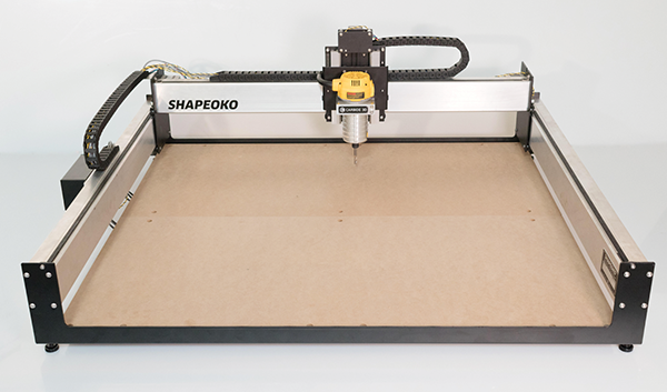
Figure 6-8: The evolved ShapeOko (photo courtesy of Carbide 3D, used by permission)
CAM (CNC Software)
Zach and Edward didn’t stop at creating an affordable desktop machine. They knew that if they really wanted to make CNC machining an accessible option for makers and hobbyists, they would have to make the software side of the equation just as approachable.
Computer-aided manufacturing (CAM) software is like a bridge. It’s what translates the digital designs from their native file formats like .dxf or .stl into a language that the CNC machine can understand. More specifically, it needs to understand what to cut (like the actual shape of the object) as well as how to cut it. The how to cut information includes instructions for how fast the end mill should spin, how deep it should make each pass, what order it should make the cuts, and so forth. These are the “feeds and speeds,” as they’re called. There are a lot of rules that govern how best to optimize. I’ve barely scratched the surface myself.
To streamline that process, the Inventables team created Easel, a web-based CAD program. The program helps you easily create simple shapes and designs and export them to your CNC machine. It’s an easy-to-use drawing program with added options such as the ability to control the target depth and plunge rate (both “feeds and speeds” terms).
They’ve set up guides and tutorials for using Easel on the Inventables website, and these walk-throughs can also serve as a great introduction to CAM. If and when you continue your CNC practice, you’ll eventually want to move to more robust CAM software like VCarve Pro or CUT3D.
Electronics 101
Do you know Ohm’s law?
I didn’t. I mean, I’m sure I learned it at some point in my life, but I couldn’t remember it when the instructor of the Basic Electronics class at TechShop looked around the class and asked us all to confirm our understanding. He nodded at the five of us, with an “of course you know what Ohm’s law is” look on his face. I looked at everyone else and they replied with a similar nod. Uh, oh.
I quickly whipped out my phone and googled “Ohm’s law” so I wasn’t completely in the dark:
I=V/R
It means the current (I) is equal to the voltage (V) divided by the resistance (R). For someone like me who has never tinkered with electronics or taken an electrical engineering course, I’m not sure there is a good reason to know this, but I still felt stupid for not knowing. I also worried that I might have hit a major snag in my quest to make things. How much electrical engineering was my education lacking? Would I have to go back to school for this?
I sat through that class, soaking up as much as possible. Some of the talk about current and resistance went over my head, but some of it made sense. It was the tangible, hands-on part of the class that really helped me understand. This was one of the first times I had used a soldering iron, and I was still getting used to the feel of it in my hands. The beginning activities of soldering together paper clips and basic breadboarding gave me a tactical sense of how electricity was moving through these systems and how I would be able to manipulate it.
It was the actual experience of electronics that helped me to understand it, not the book reading or theoretical explanations. This has remained true for my entire electronics education. I’ve fried boards, blown LEDs, and shocked myself. I’ve made lots of mistakes, and I’m still learning a lot. Nowhere does my “enough to be dangerous” theory apply more than with electronics. I’m roughly aware of how much I don’t know and have developed a mental framework for working through challenges.
It’s worth mentioning how important understanding electronics is to making. It’s certainly possible to take part in the maker movement without learning any electronics. Joel Bukiewicz, the knife maker, is a perfect example. However, many of the most interesting projects and opportunities require at least a basic level of electronics understanding.
You don’t have to learn everything, though. So far, I’ve learned only as much as the OpenROV project has required of me: powering an Arduino and BeagleBone, powering motors, electrical shorting in water, battery chemistries (and how they relate to buoyancy). That’s a very small sampling of the entirety of electronics, but it’s gotten me where I need to be.
Framing your electronics education in terms of a project like OpenROV is a great way to make the learning relevant and manageable in scope. Now if I want to start another electronics project, I have the base knowledge of everything I learned through building OpenROV to build off.
This project-based, experiential style has worked wonders for me and has turned electrical engineering from an intimidating academic study into an interesting series of experiments.
Charles Platt wrote an entire book on the subject based on this style. I started with his book Make: Electronics (Make Media, 2014), and highly recommend it to other beginners who are interested in building a working knowledge of electronics for their future projects. If nothing else, it will certainly do a better job of explaining Ohm’s law.
Arduino and Beyond
As broad and intimidating as learning electronics can be, it was surprising to me how quickly I was able to actually start doing stuff with what I was learning. And I mean more than just blinking an LED light. A basic understanding of electronics is enough to get you working with Arduino, an open source electronics platform.
The Arduino boards are the gateway to making your projects move, listen, sense, and react. The board uses a microcontroller and a user-friendly programming environment to bring your designs and projects to life.
Unfortunately, my simple definition doesn’t do Arduino justice. Phil Torrone (http://bit.ly/1eZGx7h) came up with the better explanation:
The “what” is still a little vague, and that’s the Arduino’s strength. It’s the glue people use to connect tasks together. The best way to describe an Arduino is with a few examples.
Want to have a coffee pot tweet when the coffee is ready? Arduino.
Want to have plushie steaks glow? Arduino.
How about getting an alert on your phone when there’s physical mail in your mailbox? Arduino.
Want to have a Professor X Steampunk wheelchair that speaks and dispenses booze? Arduino.
Want to make a set of quiz buzzers for an event out of Staples Easy Buttons? Arduino.
Want to make a light-up arm cannon from Metroid for your son? Arduino.
Want to make your own heart rate monitor for cycling that logs to a memory card? Arduino.
Want to make a robot that draws on the ground, or rides around in the snow? Arduino.
Don’t let the programming aspect scare you off. As someone who had never worked with electronics or learned much more than basic HTML and CSS programming, I was worried. But I quickly got the hang of it once I understood what the microcontroller was capable of: listening to commands (like a key on your keyboard) or sensor input (like gyroscopes, accelerometers, or compasses) and turning that into physical interactions like controlling actuators (LEDs, servos, motors, or electronic speed controllers). I’m by no means a programmer, but I’ve been able to effectively use the intuitive Arduino developer environment. In fact, I’d say that learning to program Arduino boards has actually increased my programming abilities and understanding beyond microcontrollers—a perfect stepping-stone into programming.
And, as with everything else in the maker world, there are broad shoulders to stand on. The Arduino community has created vast libraries of code to do everything from read accelerometer data to control electronic speed controllers. The community has done almost everything imaginably possible with a microcontroller. There is usually a chunk of code that is at least similar to your specific need. For many projects, getting the Arduino to behave the way you want it to is a matter of finding the right library and modifying it to your needs.
Where the Arduino leaves off, makers have picked right up. The falling costs and ease of manufacturing of printed circuit boards (another Gershenfeld vision for the future) and the open source modularity of the Arduino have created a Cambrian explosion of “shields,” additional boards that can be plugged on top of the Arduino to extend its capabilities. A quick tour of Maker Shed, Adafruit, or SparkFun will turn up dozens of options for shields—everything from LED displays to GPS loggers, as well as “protoshields” that allow you to design your own custom shields.
Some combination of intuitive design, ease of use for non-engineers, extensive libraries, open source development, and a large community of supportive developers has made Arduino the go-to prototyping platform for maker electronics projects. Phil Torrone was right; for makers, Arduino is here to stay.
Here are some more resources:
- Arduino: arduino.cc
- SparkFun: What Is an Arduino? learn.sparkfun.com/tutorials/what-is-an-arduino
- Adafruit: Learn Arduino: learn.adafruit.com/category/learn-arduino
- Make: Arduino Projects: makezine.com/category/technology/arduino
- Getting Started with Arduino, 3rd Edition, by Massimo Banzi and Michael Shiloh (Maker Media, 2014)
Microcontrollers aren’t the only computing devices participating in the maker movement. Now, microprocessors, the “thinking” computers that run the devices like your smartphone or tablet, are getting involved. Miniature Linux computers, or “systems on a chip” (SoC), like the Raspberry Pi and the BeagleBone Black, are becoming important maker tools and adding another complete layer of functionality to project possibilities.
Raspberry Pi, a $35 general-purpose computer, created waves when it was announced, and eager customers waited for months to get their hands on one. It’s been a few years since the release, and there are now millions of these devices in the wild.
The difference between Arduino and Raspberry Pi or BeagleBone is an important one. The Raspberry Pi doesn’t replace the Arduino. It actually adds to it. Take our OpenROV, for example, which runs both a BeagleBone as well as a microcontroller board inside the small underwater robot. The BeagleBone does much of the heavy lifting, such as processing the digital video from the webcam and running the Node.js software that is used to access control of the ROV from your browser. However, the BeagleBone is not great at running motors, so we’ve added a microcontroller to our BeagleBone Cape (the same concept as an Arduino Shield—an additional PCB with more functionality) that runs Arduino code to control the motors and servos. The OpenROV blends the best of both worlds.
These new miniature computers are still evolving, so we’re still learning what’s possible with these devices. Already, we’re starting to see robots with computer vision and arcade game coffee tables. Especially if you’re already familiar with Linux and software development, the opportunity to create new and useful projects with these tools is wide open. It’s a whole new world!
Here are some more resources for you to check out:
- Raspberry Pi: raspberrypi.org
- Adafruit: Learn Raspberry Pi: learn.adafruit.com/category/learn-raspberry-pi
- SparkFun: Raspberry Pi Tutorials: learn.sparkfun.com/tutorials/tags/raspberry-pi
- Getting Started with Raspberry Pi, 3rd Edition, by Matt Richardson and Shawn Wallace (Maker Media, 2016)
- BeagleBone Black: beagleboard.org/black
- Adafruit: Learn BeagleBone: learn.adafruit.com/category/beaglebone
- SparkFun: BeagleBone Tutorials: learn.sparkfun.com/tutorials/tags/beaglebone
- Linux for Makers, by Aaron Newcomb (Maker Media, 2017)