Chapter 11 Secure Network Architecture and Securing Network Components
THE CISSP EXAM TOPICS COVERED IN THIS CHAPTER INCLUDE:
Domain 4: Communication and Network Security
4.1 Implement secure design principles in network architectures
4.1.1 Open System Interconnection (OSI) and Transmission Control Protocol/Internet Protocol (TCP/IP) models
4.1.2 Internet Protocol (IP) networking
4.1.3 Implications of multilayer protocols
4.1.4 Converged protocols
4.1.5 Software-defined networks
4.1.6 Wireless networks
4.2 Secure network components
4.2.1 Operation of hardware
4.2.2 Transmission media
4.2.3 Network Access Control (NAC) devices
4.2.4 Endpoint security
4.2.5 Content-distribution networks
Computers and networks emerge from the integration of communication devices, storage devices, processing devices, security devices, input devices, output devices, operating systems, software, services, data, and people. This chapter discusses the Open Systems Interconnection (OSI) model as a guiding principle in networking, cabling, wireless connectivity, Transmission Control Protocol/Internet Protocol (TCP/IP) and related protocols, networking devices, and firewalls.
The Communication and Network Security domain for the CISSP certification exam deals with topics related to network components (i.e., network devices and protocols), specifically, how they function and how they are relevant to security. This domain is discussed in this chapter and in Chapter 12, “Secure Communications and Network Attacks.” Be sure to read and study the materials in both chapters to ensure complete coverage of the essential material for the CISSP certification exam.
OSI Model
Communications between computers over networks are made possible by protocols. A protocol is a set of rules and restrictions that define how data is transmitted over a network medium (e.g., twisted-pair cable, wireless transmission). In the early days of network development, many companies had their own proprietary protocols, which meant interaction between computers of different vendors was often difficult, if not impossible. In an effort to eliminate this problem, the International Organization for Standardization (ISO) developed the Open Systems Interconnection (OSI) Reference Model for protocols in the early 1980s. Specifically, ISO 7498 defines the OSI Reference Model (more commonly called the OSI model). Understanding the OSI model and how it relates to network design, deployment, and security is essential in preparing for the CISSP exam.
In order to properly implement secure design principles in network architectures, it is important to fully understand all of the technologies involved in computer communications. From hardware and software to protocols and encryption and beyond, there are lots of details to know, standards to understand, and procedures to follow. Additionally, the basis of secure network architecture and design is a thorough knowledge of the OSI and TCP/IP models as well as Internet Protocol (IP) networking in general.
History of the OSI Model
The OSI model wasn’t the first or only attempt to streamline networking protocols or establish a common communications standard. In fact, the most widely used protocol today, TCP/IP (which is based on the DARPA model, also known now as the TCP/IP model), was developed in the early 1970s. The OSI model was not developed until the late 1970s.
The OSI protocol was developed to establish a common communication structure or standard for all computer systems. The actual OSI protocol was never widely adopted, but the theory behind the OSI protocol, the OSI model, was readily accepted. The OSI model serves as an abstract framework, or theoretical model, for how protocols should function in an ideal world on ideal hardware. Thus, the OSI model has become a common reference point against which all protocols can be compared and contrasted.
OSI Functionality
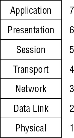
The OSI model divides networking tasks into seven distinct layers. Each layer is responsible for performing specific tasks or operations for the ultimate goal of supporting data exchange (in other words, network communication) between two computers. The layers are always numbered from bottom to top (see Figure 11.1). They are referred to by either their name or their layer number. For example, layer 3 is also known as the Network layer. The layers are ordered specifically to indicate how information flows through the various levels of communication. Each layer communicates directly with the layer above it as well as the layer below it, plus the peer layer on a communication partner system.
The OSI model is an open network architecture guide for network product vendors. This standard, or guide, provides a common foundation for the development of new protocols, networking services, and even hardware devices. By working from the OSI model, vendors are able to ensure that their products will integrate with products from other companies and be supported by a wide range of operating systems. If all vendors developed their own networking framework, interoperability between products from different vendors would be next to impossible.
The real benefit of the OSI model is its expression of how networking actually functions. In the most tangible sense, network communications occur over a physical connection (whether that physical connection is electrons over copper, photons over fiber, or radio signals through the air). Physical devices establish channels through which electronic signals can pass from one computer to another. These physical device channels are only one type of the seven logical communication types defined by the OSI model. Each layer of the OSI model communicates via a logical channel with its peer layer on another computer. This enables protocols based on the OSI model to support a type of authentication by being able to identify the remote communication entity as well as authenticate the source of the received data.
Encapsulation/Deencapsulation
Protocols based on the OSI model employ a mechanism called encapsulation. Encapsulation is the addition of a header, and possibly a footer, to the data received by each layer from the layer above before it’s handed off to the layer below. As the message is encapsulated at each layer, the previous layer’s header and payload combine to become the payload of the current layer. Encapsulation occurs as the data moves down through the OSI model layers from Application to Physical. The inverse action occurring as data moves up through the OSI model layers from Physical to Application is known as deencapsulation. The encapsulation/deencapsulation process is as follows:
The Application layer creates a message.
The Application layer passes the message to the Presentation layer.
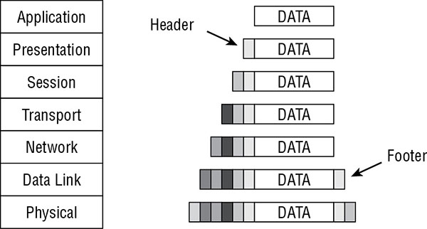
The Presentation layer encapsulates the message by adding information to it. Information is usually added only at the beginning of the message (called a header); however, some layers also add material at the end of the message (called a footer), as shown in Figure 11.2.
The process of passing the message down and adding layer-specific information continues until the message reaches the Physical layer.
At the Physical layer, the message is converted into electrical impulses that represent bits and is transmitted over the physical connection.
The receiving computer captures the bits from the physical connection and re-creates the message in the Physical layer.
The Physical layer converts the message from bits into a Data Link frame and sends the message up to the Data Link layer.
The Data Link layer strips its information and sends the message up to the Network layer.
This process of deencapsulation is performed until the message reaches the Application layer.
When the message reaches the Application layer, the data in the message is sent to the intended software recipient.
FIGURE 11.2 Representation of OSI model encapsulation
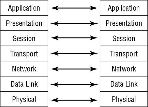
The information removed by each layer contains instructions, checksums, and so on that can be understood only by the peer layer that originally added or created the information (see Figure 11.3). This information is what creates the logical channel that enables peer layers on different computers to communicate.
FIGURE 11.3 Representation of the OSI model peer layer logical channels
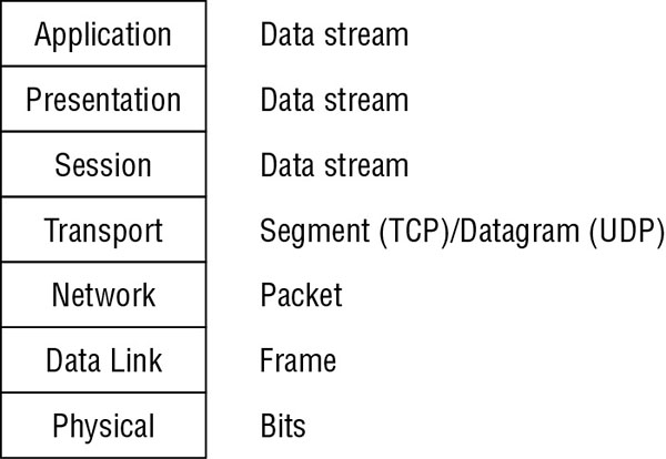
The message sent into the protocol stack at the Application layer (layer 7) is called the data stream. It retains the label of data stream (or sometimes the label of protocol data unit [PDU] is applied) until it reaches the Transport layer (layer 4), where it is called a segment (TCP protocols) or a datagram (User Datagram Protocol [UDP] protocols). In the Network layer (layer 3), it is called a packet. In the Data Link layer (layer 2), it is called a frame. In the Physical layer (layer 1), the data has been converted into bits for transmission over the physical connection medium. Figure 11.4 shows how each layer changes the data through this process.
Understanding the functions and responsibilities of each layer of the OSI model will help you understand how network communications function, how attacks can be perpetrated against network communications, and how security can be implemented to protect network communications. We discuss each layer, starting with the bottom layer, in the following sections.
Remember the OSI To make the most of the OSI, you must first be able to remember the names of the seven layers in their proper order. One common method of memorizing them is to create a mnemonic from the initial letters of the layer names so they are easier to remember. One of our favorites is Please Do Not Teach Surly People Acronyms. Do take note that this memorization mnemonic works from the Physical layer up to the Application layer. A mnemonic working from the Application layer down is All Presidents Since Truman Never Did Pot. There are many other OSI memorization schemes out there; just be sure you know whether they are top-down or bottom-up.
Physical Layer
The Physical layer (layer 1) accepts the frame from the Data Link layer and converts the frame into bits for transmission over the physical connection medium. The Physical layer is also responsible for receiving bits from the physical connection medium and converting them into a frame to be used by the Data Link layer.
The Physical layer contains the device drivers that tell the protocol how to employ the hardware for the transmission and reception of bits. Located within the Physical layer are electrical specifications, protocols, and interface standards such as the following:
EIA/TIA-232 and EIA/TIA-449
X.21
High-Speed Serial Interface (HSSI)
Synchronous Optical Networking (SONET)
V.24 and V.35
Through the device drivers and these standards, the Physical layer controls throughput rates, handles synchronization, manages line noise and medium access, and determines whether to use digital or analog signals or light pulses to transmit or receive data over the physical hardware interface.
Network hardware devices that function at layer 1, the Physical layer, are network interface cards (NICs), hubs, repeaters, concentrators, and amplifiers. These devices perform hardware-based signal operations, such as sending a signal from one connection port out on all other ports (a hub) or amplifying the signal to support greater transmission distances (a repeater).
Data Link Layer
The Data Link layer (layer 2) is responsible for formatting the packet from the Network layer into the proper format for transmission. The proper format is determined by the hardware and the technology of the network. There are numerous possibilities, such as Ethernet (IEEE 802.3), Token Ring (IEEE 802.5), asynchronous transfer mode (ATM), Fiber Distributed Data Interface (FDDI), and Copper DDI (CDDI). However, only Ethernet remains a common Data Link layer technology in use in modern networks. Within the Data Link layer resides the technology-specific protocols that convert the packet into a properly formatted frame. Once the frame is formatted, it is sent to the Physical layer for transmission.
The following list includes some of the protocols found within the Data Link layer:
Serial Line Internet Protocol (SLIP)
Point-to-Point Protocol (PPP)
Address Resolution Protocol (ARP)
Layer 2 Forwarding (L2F)
Layer 2 Tunneling Protocol (L2TP)
Point-to-Point Tunneling Protocol (PPTP)
Integrated Services Digital Network (ISDN)
Part of the processing performed on the data within the Data Link layer includes adding the hardware source and destination addresses to the frame. The hardware address is the Media Access Control (MAC) address, which is a 6-byte (48-bit) binary address written in hexadecimal notation (for example, 00-13-02-1F-58-F5). The first 3 bytes (24 bits) of the address denote the vendor or manufacturer of the physical network interface. This is known as the Organizationally Unique Identifier (OUI). OUIs are registered with the Institute of Electrical and Electronics Engineers (IEEE), which controls their issuance. The OUI can be used to discover the manufacturer of a NIC through the IEEE website at http://standards.ieee.org/regauth/oui/index.shtml. The last 3 bytes (24 bits) represent a unique number assigned to that interface by the manufacturer. No two devices can have the same MAC address in the same local Ethernet broadcast domain; otherwise an address conflict occurs. It is also good practice to ensure that all MAC addresses across a private enterprise network are unique. While the design of MAC addresses should make them unique, vendor errors have produced duplicate MAC addresses. When this happens either the NIC hardware must be replaced or the MAC address must be modified (i.e., spoofed) to a nonconflicting alternative address.
Among the protocols at the Data Link layer (layer 2) of the OSI model, you should be familiar with Address Resolution Protocol (ARP). ARP is used to resolve IP addresses into MAC addresses. Traffic on a network segment is directed from its source system to its destination system using MAC addresses.
ARP is carried as the payload of an Ethernet frame. Since Ethernet is layer 2, it makes sense to consider ARP layer 3. However, ARP does not operate as a true layer 3 protocol as it does not use a source/destination addressing scheme to direct communications in its header (similar to IP headers). Instead, it is dependent upon Ethernet’s source and destination MAC addresses. Thus, ARP is not a true layer 3. ARP is also not truly a full layer 2 protocol as it depends upon Ethernet to serve as its transportation host. Thus, at best it is a dependent layer 2 protocol. The OSI model is a conceptual model and not an exacting description of how real protocols operate. Thus, ARP does not fit cleanly in the OSI organization.
The Data Link layer contains two sublayers: the Logical Link Control (LLC) sublayer and the MAC sublayer. Details about these sublayers are not critical for the CISSP exam.
Network hardware devices that function at layer 2, the Data Link layer, are switches and bridges. These devices support MAC-based traffic routing. Switches receive a frame on one port and send it out another port based on the destination MAC address. MAC address destinations are used to determine whether a frame is transferred over the bridge from one network to another.
Network Layer
The Network layer (layer 3) is responsible for adding routing and addressing information to the data. The Network layer accepts the segment from the Transport layer and adds information to it to create a packet. The packet includes the source and destination IP addresses.
The routing protocols are located at this layer and include the following:
Internet Control Message Protocol (ICMP)
Routing Information Protocol (RIP)
Open Shortest Path First (OSPF)
Border Gateway Protocol (BGP)
Internet Group Management Protocol (IGMP)
Internet Protocol (IP)
Internet Protocol Security (IPSec)
Internetwork Packet Exchange (IPX)
Network Address Translation (NAT)
Simple Key Management for Internet Protocols (SKIP)
The Network layer is responsible for providing routing or delivery information, but it is not responsible for verifying guaranteed delivery (that is the responsibility of the Transport layer). The Network layer also manages error detection and node data traffic (in other words, traffic control).
Routers and bridge routers (brouters) are among the network hardware devices that function at layer 3. Routers determine the best logical path for the transmission of packets based on speed, hops, preference, and so on. Routers use the destination IP address to guide the transmission of packets. A brouter, working primarily in layer 3 but in layer 2 when necessary, is a device that attempts to route first, but if that fails, it defaults to bridging.
Transport Layer
The Transport layer (layer 4) is responsible for managing the integrity of a connection and controlling the session. It accepts a PDU (variably spelled out as Protocol Data Unit, Packet Data Unit, or Payload Data Unit—i.e., a container of information or data passed between network layers). A PDU coming from the Session layer is converted into a segment. The Transport layer, which controls how devices on the network are addressed or referenced, establishes communication connections between nodes (also known as devices) and defines the rules of a session. Session rules specify how much data each segment can contain, how to verify the integrity of data transmitted, and how to determine whether data has been lost. Session rules are established through a handshaking process, so the communicating devices are in agreement on the rules. (Please see the section “Transport Layer Protocols” later in this chapter for the discussion of the SYN/ACK three-way handshake of TCP.)
The Transport layer establishes a logical connection between two devices and provides end-to-end transport services to ensure data delivery. This layer includes mechanisms for segmentation, sequencing, error checking, controlling the flow of data, error correction, multiplexing, and network service optimization. The following protocols operate within the Transport layer:
Transmission Control Protocol (TCP)
User Datagram Protocol (UDP)
Sequenced Packet Exchange (SPX)
Secure Sockets Layer (SSL)
Transport Layer Security (TLS)
Session Layer
The Session layer (layer 5) is responsible for establishing, maintaining, and terminating communication sessions between two computers. It manages dialogue discipline or dialogue control (simplex, half-duplex, full-duplex), establishes checkpoints for grouping and recovery, and retransmits PDUs that have failed or been lost since the last verified checkpoint. The following protocols operate within the Session layer:
Network File System (NFS)
Structured Query Language (SQL)
Remote Procedure Call (RPC)
Communication sessions can operate in one of three different discipline or control modes:
Simplex One-way communication
Half-Duplex Two-way communication, but only one direction can send data at a time
Full-Duplex Two-way communication, in which data can be sent in both directions simultaneously
Presentation Layer
The Presentation layer (layer 6) is responsible for transforming data received from the Application layer into a format that any system following the OSI model can understand. It imposes common or standardized structure and formatting rules onto the data. The Presentation layer is also responsible for encryption and compression. Thus, it acts as an interface between the network and applications. This layer is what allows various applications to interact over a network, and it does so by ensuring that the data formats are supported by both systems. Most file or data formats operate within this layer. This includes formats for images, video, sound, documents, email, web pages, control sessions, and so on. The following list includes some of the format standards that exist within the Presentation layer:
American Standard Code for Information Interchange (ASCII)
The Application layer (layer 7) is responsible for interfacing user applications, network services, or the operating system with the protocol stack. It allows applications to communicate with the protocol stack. The Application layer determines whether a remote communication partner is available and accessible. It also ensures that sufficient resources are available to support the requested communications.
The application is not located within this layer; rather, the protocols and services required to transmit files, exchange messages, connect to remote terminals, and so on are found here. Numerous application-specific protocols are found within this layer, such as the following:
Hypertext Transfer Protocol (HTTP)
File Transfer Protocol (FTP)
Line Print Daemon (LPD)
Simple Mail Transfer Protocol (SMTP)
Telnet
Trivial File Transfer Protocol (TFTP)
Electronic Data Interchange (EDI)
Post Office Protocol version 3 (POP3)
Internet Message Access Protocol (IMAP)
Simple Network Management Protocol (SNMP)
Network News Transport Protocol (NNTP)
Secure Remote Procedure Call (S-RPC)
Secure Electronic Transaction (SET)
There is a network device (or service) that works at the Application layer, namely, the gateway. However, an Application layer gateway is a specific type of component. It serves as a protocol translation tool. For example, an IP-to-IPX gateway takes inbound communications from TCP/IP and translates them over to IPX/SPX for outbound transmission. Application layer firewalls also operate at this layer. Other networking devices or filtering software may observe or modify traffic at this layer.
TCP/IP Model
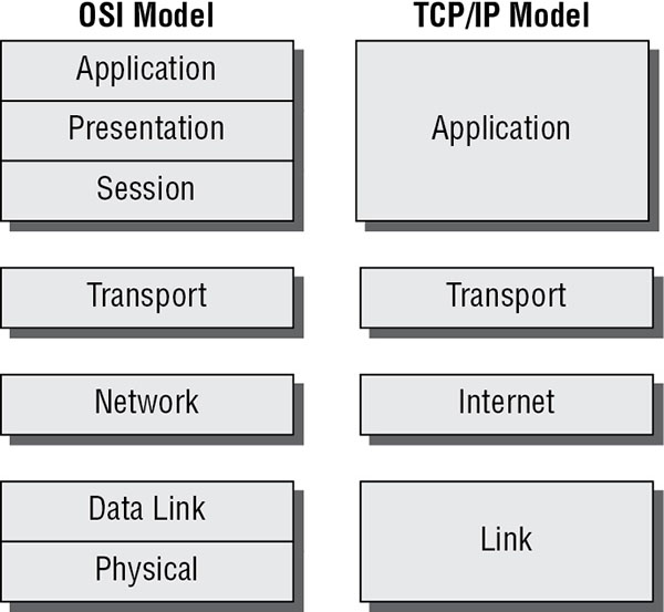
The TCP/IP model (also called the DARPA or the DOD model) consists of only four layers, as opposed to the OSI Reference Model’s seven. The four layers of the TCP/IP model are Application (also known as Process), Transport (also known as Host-to-Host), Internet (sometimes Internetworking), and Link (although Network Interface and sometimes Network Access are used). Figure 11.5 shows how they compare to the seven layers of the OSI model. The TCP/IP protocol suite was developed before the OSI Reference Model was created. The designers of the OSI Reference Model took care to ensure that the TCP/IP protocol suite fit their model because of its established deployment in networking.
FIGURE 11.5 Comparing the OSI model with the TCP/IP model
The TCP/IP model’s Application layer corresponds to layers 5, 6, and 7 of the OSI model. The TCP/IP model’s Transport layer corresponds to layer 4 from the OSI model. The TCP/IP model’s internet layer corresponds to layer 3 from the OSI model. The TCP/IP model’s Link layer corresponds to layers 1 and 2 from the OSI model.
It has become common practice (through confusion, misunderstanding, and probably laziness) to also call the TCP/IP model layers by their OSI model layer equivalent names. The TCP/IP model’s Application layer is already using a name borrowed from the OSI, so that one is a snap. The TCP/IP model’s Host-to-Host layer is sometimes called the Transport layer (the OSI model’s fourth layer). The TCP/IP model’s internet layer is sometimes called the Network layer (the OSI model’s third layer). And the TCP/IP model’s Link layer is sometimes called the Data Link or the Network Access layer (the OSI model’s second layer).
TCP/IP Protocol Suite Overview
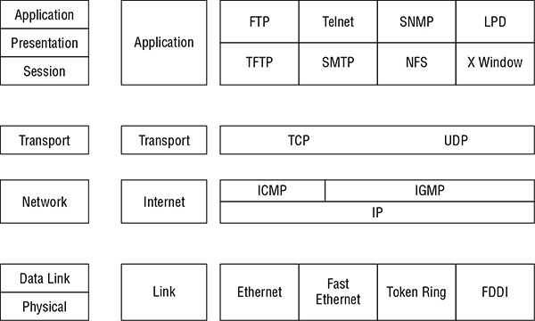
The most widely used protocol suite is TCP/IP, but it is not just a single protocol; rather, it is a protocol stack comprising dozens of individual protocols (see Figure 11.6). TCP/IP is a platform-independent protocol based on open standards. However, this is both a benefit and a drawback. TCP/IP can be found in just about every available operating system, but it consumes a significant amount of resources and is relatively easy to hack into because it was designed for ease of use rather than for security.
FIGURE 11.6 The four layers of TCP/IP and its component protocols
TCP/IP can be secured using virtual private network (VPN) links between systems. VPN links are encrypted to add privacy, confidentiality, and authentication and to maintain data integrity. Protocols used to establish VPNs are Point-to-Point Tunneling Protocol (PPTP), Layer 2 Tunneling Protocol (L2TP), Secure Shell (SSH), OpenVPN (SSL/TLS VPNs), and Internet Protocol Security (IPSec). Another method to provide protocol-level security is to employ TCP wrappers. A TCP wrapper is an application that can serve as a basic firewall by restricting access to ports and resources based on user IDs or system IDs. Using TCP wrappers is a form of port-based access control.
Transport Layer Protocols
The two primary Transport layer protocols of TCP/IP are TCP and UDP. Transmission Control Protocol (TCP) is a full-duplex connection-oriented protocol, whereas User Datagram Protocol (UDP) is a simplex connectionless protocol. When a communication connection is established between two systems, it is done using ports. TCP and UDP each have 65,536 ports. Since port numbers are 16-digit binary numbers, the total number of ports is 2^16, or 65,536, numbered from 0 through 65,535. A port is little more than an address number that both ends of the communication link agree to use when transferring data within the Transport layer. Ports allow a single IP address to be able to support multiple simultaneous communications, each using a different port number. The combination of an IP address and a port number is known as a socket.
The first 1,024 of these ports (0–1,023) are called the well-known ports or the service ports. This is because they have standardized assignments as to the services they support. For example, port 80 is the standard port for web (HTTP) traffic, port 23 is the standard port for Telnet, and port 25 is the standard port for SMTP. These ports are reserved for use exclusively by servers (in other words, they cannot be used as the source port by a requesting client). You can find a list of ports worth knowing for the exam in the section “Common Application Layer Protocols” later in this chapter.
Ports 1,024 to 49151 are known as the registered software ports. These are ports that have one or more networking software products specifically registered with the International Assigned Numbers Authority (IANA, www.iana.org) in order to provide a standardized port-numbering system for clients attempting to connect to their products.
Ports 49152 to 65535 are known as the random, dynamic, or ephemeral ports because they are often used randomly and temporarily by clients as a source port. These random ports are also used by several networking services when negotiating a data transfer pipeline between client and server outside the initial service or registered ports, such as performed by common FTP.
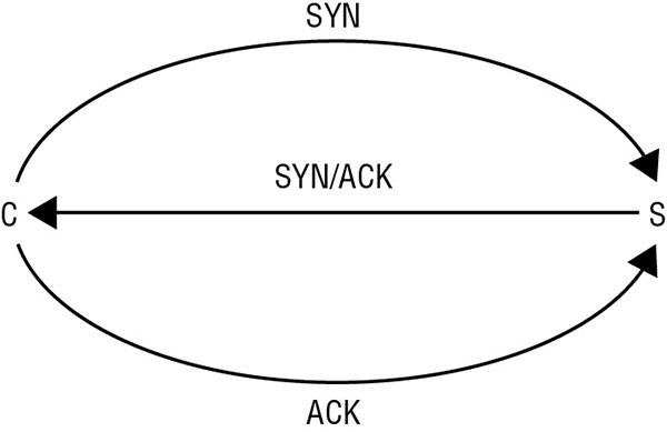
Transmission Control Protocol (TCP) operates at layer 4 (the Transport layer) of the OSI model. It supports full-duplex communications, is connection oriented, and employs reliable sessions. TCP is connection oriented because it employs a handshake process between two systems to establish a communication session. Upon completion of this handshake process, a communication session that can support data transmission between the client and server is established. The three-way handshake process (Figure 11.7) is as follows:
The client sends a SYN (synchronize) flagged packet to the server.
The server responds with a SYN/ACK (synchronize and acknowledge) flagged packet back to the client.
The client responds with an ACK (acknowledge) flagged packet back to the server.
When a communication session is complete, there are two methods to disconnect the TCP session. First, and most common, is the use of FIN (finish) flagged packets instead of SYN flagged packets. Each side of a conversation will transmit a FIN flagged packet once all of its data is transmitted, triggering the opposing side to confirm with an ACK flagged packet. Thus, it takes four packets to gracefully tear down a TCP session. Second is the use of an RST (reset) flagged packet, which causes an immediate and abrupt session termination. (Please see the discussion of the TCP header flag later in this section.)
The segments of a TCP transmission are tagged with a sequence number. This allows the receiver to rebuild the original communication by reordering received segments back into their proper arrangement in spite of the order in which they were received. Data communicated through a TCP session is periodically verified with an acknowledgment. The acknowledgment is sent by the receiver back to the sender by setting the TCP header’s acknowledgment sequence value to the last sequence number received from the sender within the transmission window. The number of packets transmitted before an acknowledge packet is sent is known as the transmission window. Data flow is controlled through a mechanism called sliding windows. TCP is able to use different sizes of windows (in other words, a different number of transmitted packets) before sending an acknowledgment. Larger windows allow for faster data transmission, but they should be used only on reliable connections where lost or corrupted data is minimal. Smaller windows should be used when the communication connection is unreliable. TCP should be employed when the delivery of data is required. Sliding windows allow this size to vary dynamically because the reliability of the TCP session changes while in use. In the event that all packets of a transmission window were not received, no acknowledgment is sent. After a timeout period, the sender will resend the entire transmission window set of packets again.
The TCP header is relatively complex when compared to the other common Transport layer protocol, UDP. A TCP header is 20 to 60 bytes long. This header is divided into several sections, or fields, as detailed in Table 11.1.
TABLE 11.1TCP header construction (ordered from beginning of header to end)
All of these fields have unique parameters and requirements, most of which are beyond the scope of the CISSP exam. However, you should be familiar with the details of the flags field. The flags field can contain a designation of one or more flags, or control bits. These flags indicate the function of the TCP packet and request that the recipient respond in a specific manner. The flags field is 8 bits long. Each of the bit positions represents a single flag, or control setting. Each position can be set on with a value of 1 or off with a value of 0. There are some conditions in which multiple flags can be enabled at once (in other words, the second packet in the TCP three-way handshake when both the SYN and ACK flags are set). Table 11.2 details the flag control bits.
Used to manage transmission over congested links; see RFC 3168
ECE
ECN-Echo (Explicit Congestion Notification)
Used to manage transmission over congested links; see RFC 3168
URG
Urgent
Indicates urgent data
ACK
Acknowledgment
Acknowledges synchronization or shutdown request
PSH
Push
Indicates need to push data immediately to application
RST
Reset
Causes immediate disconnect of TCP session
SYN
Synchronization
Requests synchronization with new sequencing numbers
FIN
Finish
Requests graceful shutdown of TCP session
An additional important tidbit is that the IP header protocol field value for TCP is 6 (0x06). The protocol field value is the label or flag found in the header of every IP packet that tells the receiving system what type of packet it is. The IP header’s protocol field indicates the identity of the next encapsulated protocol (in other words, the protocol contained in the payload from the current protocol layer, such as ICMP or IGMP, or the next layer up, such as TCP or UDP). Think of it as like the label on a mystery-meat package wrapped in butcher paper you pull out of the freezer. Without the label, you would have to open it and inspect it to figure out what it was. But with the label, you can search or filter quickly to find items of interest. For a list of other protocol field values, please visit www.iana.org/assignments/protocol-numbers.
User Datagram Protocol (UDP) also operates at layer 4 (the Transport layer) of the OSI model. It is a connectionless “best-effort” communications protocol. It offers no error detection or correction, does not use sequencing, does not use flow control mechanisms, does not use a preestablished session, and is considered unreliable. UDP has very low overhead and thus can transmit data quickly. However, UDP should be used only when the delivery of data is not essential. UDP is often employed by real-time or streaming communications for audio and/or video. The IP header protocol field value for UDP is 17 (0x11).
As mentioned earlier, the UDP header is relatively simple in comparison with the TCP header. A UDP header is 8 bytes (64 bits) long. This header is divided into four sections, or fields (each 16 bits long):
Source port
Destination port
Message length
Checksum
Network Layer Protocols and IP Networking Basics
Another important protocol in the TCP/IP protocol suite operates at the Network layer of the OSI model, namely, Internet Protocol (IP). IP provides route addressing for data packets. It is this route addressing that is the foundation of global internet communications because it provides a means of identity and prescribes transmission paths. Similar to UDP, IP is connectionless and is an unreliable datagram service. IP does not offer guarantees that packets will be delivered or that packets will be delivered in the correct order, and it does not guarantee that packets will be delivered only once. Thus, you must employ TCP on IP to gain reliable and controlled communication sessions.
IP classes
Basic knowledge of IP addressing and IP classes is a must for any security professional. If you are rusty on addressing, subnetting, classes, and other related topics, take the time to refresh yourself. Table 11.3 and Table 11.4 provide a quick overview of the key details of classes and default subnets. A full Class A subnet supports 16,777,214 hosts; a full class B subnet supports 65,534 hosts; and a full Class C subnet supports 254 hosts. Class D is used for multicasting, while Class E is reserved for future use.
Note that the entire Class A network of 127 was set aside for the loopback address, although only a single address is actually needed for that purpose.
Another option for subnetting is to use Classless Inter-Domain Routing (CIDR) notation. CIDR uses mask bits rather than a full dotted-decimal notation subnet mask. Thus, instead of 255.255.0.0, a CIDR is added to the IP address after a slash, as in 172.16.1.1/16, for example. One significant benefit of CIDR over traditional subnet-masking techniques is the ability to combine multiple noncontiguous sets of addresses into a single subnet. For example, it is possible to combine several Class C subnets into a single larger subnet grouping. If CIDR piques your interest, see the CIDR article on Wikipedia or visit the IETF’s RFC for CIDR at http://tools.ietf.org/html/rfc4632.
ICMP and IGMP are other protocols in the Network layer of the OSI model:
ICMPInternet Control Message Protocol (ICMP) is used to determine the health of a network or a specific link. ICMP is utilized by ping, traceroute, pathping, and other network management tools. The ping utility employs ICMP echo packets and bounces them off remote systems. Thus, you can use ping to determine whether the remote system is online, whether the remote system is responding promptly, whether the intermediary systems are supporting communications, and the level of performance efficiency at which the intermediary systems are communicating. The ping utility includes a redirect function that allows the echo responses to be sent to a different destination than the system of origin.
Unfortunately, the features of ICMP were often exploited in various forms of bandwidth-based denial-of-service (DoS) attacks, (DoS), such as ping of death, smurf attacks, and ping floods. This fact has shaped how networks handle ICMP traffic today, resulting in many networks limiting the use of ICMP or at least limiting its throughput rates. Ping of death sends a malformed ping larger than 65,535 bytes (larger than the maximum IPv4 packet size) to a computer to attempt to crash it. Smurf attacks generate enormous amounts of traffic on a target network by spoofing broadcast pings, and ping floods are a basic DoS attack relying on consuming all of the bandwidth that a target has available.
You should be aware of several important details regarding ICMP. First, the IP header protocol field value for ICMP is 1 (0x01). Second, the type field in the ICMP header defines the type or purpose of the message contained within the ICMP payload. There are more than 40 defined types, but only 7 are commonly used (see Table 11.5). You can find a complete list of the ICMP type field values at www.iana.org/assignments/icmp-parameters. It may be worth noting that many of the types listed may also support codes. A code is simply an additional data parameter offering more detail about the function or purpose of the ICMP message payload. One example of an event that would cause an ICMP response is when an attempt is made to connect to a UDP service port when that service and port are not actually in use on the target server; this would cause an ICMP Type 3 response back to the origin. Since UDP does not have a means to send back errors, the protocol stack switches to ICMP for that purpose.
IGMPInternet Group Management Protocol (IGMP) allows systems to support multicasting. Multicasting is the transmission of data to multiple specific recipients. (RFC 1112 discusses the requirements to perform IGMP multicasting.) IGMP is used by IP hosts to register their dynamic multicast group membership. It is also used by connected routers to discover these groups. Through the use of IGMP multicasting, a server can initially transmit a single data signal for the entire group rather than a separate initial data signal for each intended recipient. With IGMP, the single initial signal is multiplied at the router if divergent pathways exist to the intended recipients. The IP header protocol field value for IGMP is 2 (0x02).
ARPAddress Resolution Protocol (ARP) is essential to the interoperability of logical and physical addressing schemes. ARP is used to resolve IP addresses (32-bit binary number for logical addressing) into Media Access Control (MAC) addresses (48-bit binary number for physical addressing)—or EUI-48 or even EUI-64. Traffic on a network segment (for example, cables across a hub) is directed from its source system to its destination system using MAC addresses.
ARP uses caching and broadcasting to perform its operations. The first step in resolving an IP address into a MAC address, or vice versa, is to check the local ARP cache. If the needed information is already present in the ARP cache, it is used. This activity is sometimes abused using a technique called ARP cache poisoning, where an attacker inserts bogus information into the ARP cache. If the ARP cache does not contain the necessary information, an ARP request in the form of a broadcast is transmitted. If the owner of the queried address is in the local subnet, it can respond with the necessary information. If not, the system will default to using its default gateway to transmit its communications. Then, the default gateway (in other words, a router) will need to perform its own ARP process.
Common Application Layer Protocols
In the Application layer of the TCP/IP model (which includes the Session, Presentation, and Application layers of the OSI model) reside numerous application- or service-specific protocols. A basic knowledge of these protocols and their relevant service ports is important for the CISSP exam:
Telnet, TCP Port 23 This is a terminal emulation network application that supports remote connectivity for executing commands and running applications but does not support transfer of files.
File Transfer Protocol (FTP), TCP Ports 20 (Passive Data)/Ephemeral (Active Data) and 21 (Control Connection) This is a network application that supports an exchange of files that requires anonymous or specific authentication.
Trivial File Transfer Protocol (TFTP), UDP Port 69 This is a network application that supports an exchange of files that does not require authentication.
Simple Mail Transfer Protocol (SMTP), TCP Port 25 This is a protocol used to transmit email messages from a client to an email server and from one email server to another.
Post Office Protocol (POP3), TCP Port 110 This is a protocol used to pull email messages from an inbox on an email server down to an email client.
Internet Message Access Protocol (IMAP), TCP Port 143 This is a protocol used to pull email messages from an inbox on an email server down to an email client. IMAP is more secure than POP3 and offers the ability to pull headers down from the email server as well as to delete messages directly off the email server without having to download to the local client first.
Dynamic Host Configuration Protocol (DHCP), UDP Ports 67 and 68 DHCP uses port 67 as the destination port on the server to receive client communications and port 68 as the source port for client requests. It is used to assign TCP/IP configuration settings to systems upon bootup. DHCP enables centralized control of network addressing.
Hypertext Transfer Protocol (HTTP), TCP Port 80 This is the protocol used to transmit web page elements from a web server to web browsers.
Secure Sockets Layer (SSL), TCP Port 443 (for HTTP Encryption) This is a VPN-like security protocol that operates at the Transport layer. SSL was originally designed to support secured web communications (HTTPS) but is capable of securing any Application layer protocol communications.
Line Print Daemon (LPD), TCP Port 515 This is a network service that is used to spool print jobs and to send print jobs to printers.
X Window, TCP Ports 6000–6063 This is a GUI API for command-line operating systems.
Network File System (NFS), TCP Port 2049 This is a network service used to support file sharing between dissimilar systems.
Simple Network Management Protocol (SNMP), UDP Port 161 (UDP Port 162 for Trap Messages) This is a network service used to collect network health and status information by polling monitoring devices from a central monitoring station.
Implications of Multilayer Protocols
As you can see from the previous sections, TCP/IP as a protocol suite comprises dozens of individual protocols spread across the various protocol stack layers. TCP/IP is therefore a multilayer protocol. TCP/IP derives several benefits from its multilayer design, specifically in relation to its mechanism of encapsulation. For example, when communicating between a web server and a web browser over a typical network connection, HTTP is encapsulated in TCP, which in turn is encapsulated in IP, which is in turn encapsulated in Ethernet. This could be presented as follows:
[ Ethernet [ IP [ TCP [ HTTP ] ] ] ]
However, this is not the extent of TCP/IP’s encapsulation support. It is also possible to add additional layers of encapsulation. For example, adding SSL/TLS encryption to the communication would insert a new encapsulation between HTTP and TCP:
[ Ethernet [ IP [ TCP [ SSL [ HTTP ] ] ] ] ]
This in turn could be further encapsulated with a Network layer encryption such as IPSec:
However, encapsulation is not always implemented for benign purposes. There are numerous covert channel communication mechanisms that use encapsulation to hide or isolate an unauthorized protocol inside another authorized one. For example, if a network blocks the use of FTP but allows HTTP, then tools such as HTTP Tunnel can be used to bypass this restriction. This could result in an encapsulation structure such as this:
[ Ethernet [ IP [ TCP [ HTTP [ FTP ] ] ] ]
Normally, HTTP carries its own web-related payload, but with the HTTP Tunnel tool, the standard payload is replaced with an alternative protocol. This false encapsulation can even occur lower in the protocol stack. For example, ICMP is typically used for network health testing and not for general communication. However, with utilities such as Loki, ICMP is transformed into a tunnel protocol to support TCP communications. The encapsulation structure of Loki is as follows:
[ Ethernet [ IP [ ICMP [ TCP [ HTTP ] ] ] ] ]
Another area of concern caused by unbounded encapsulation support is the ability to jump between virtual local area networks (VLANs). VLANs are network segments that are logically separated by tags. This attack, known as VLAN hopping, is performed by creating a double-encapsulated IEEE 802.1Q VLAN tag:
With this double encapsulation, the first encountered switch will strip away the first VLAN tag, and then the next switch will be fooled by the interior VLAN tag and move the traffic into the other VLAN.
Multilayer protocols provide the following benefits:
A wide range of protocols can be used at higher layers.
Encryption can be incorporated at various layers.
Flexibility and resiliency in complex network structures is supported.
There are a few drawbacks of multilayer protocols:
Covert channels are allowed.
Filters can be bypassed.
Logically imposed network segment boundaries can be overstepped.
TCP/IP Vulnerabilities
TCP/IP’s vulnerabilities are numerous. Improperly implemented TCP/IP stacks in various operating systems are vulnerable to buffer overflows, SYN flood attacks, various denial-of-service (DoS) attacks, fragment attacks, oversized packet attacks, spoofing attacks, man-in-the-middle attacks, hijack attacks, and coding error attacks.
TCP/IP (as well as most protocols) is also subject to passive attacks via monitoring or sniffing. Network monitoring is the act of monitoring traffic patterns to obtain information about a network. Packet sniffing is the act of capturing packets from the network in hopes of extracting useful information from the packet contents. Effective packet sniffers can extract usernames, passwords, email addresses, encryption keys, credit card numbers, IP addresses, system names, and so on.
Packet sniffing and other attacks are discussed in more detail in Chapter 13.
Domain Name System
Addressing and naming are important components that make network communications possible. Without addressing schemes, networked computers would not be able to distinguish one computer from another or specify the destination of a communication. Likewise, without naming schemes, humans would have to remember and rely on numbering systems to identify computers. It is much easier to remember Google.com than 64.233.187.99. Thus, most naming schemes were enacted for human use rather than computer use.
It is reasonably important to grasp the basic ideas of addressing and numbering as used on TCP/IP-based networks. There are three different layers to be aware of. They’re presented in reverse order here because the third layer is the most basic:
The third, or bottom, layer is the MAC address. The MAC address, or hardware address, is a “permanent” physical address.
The second, or middle, layer is the IP address. The IP address is a “temporary” logical address assigned over or onto the MAC address.
The top layer is the domain name. The domain name or computer name is a “temporary” human-friendly convention assigned over or onto the IP address.
This system of naming and addressing grants each networking component the information it needs while making its use of that information as simple as possible. Humans get human-friendly domain names, networking protocols get router-friendly IP addresses, and the network interfaces get physical addresses. However, all three of these schemes must be linked together to allow interoperability. Thus, the Domain Name System (DNS) and the ARP system were developed to interchange or resolve between domain names and IP addresses or IP addresses and MAC addresses respectively. DNS resolves a human-friendly domain name into its IP address equivalent. Then, ARP resolves the IP address into its MAC address equivalent. It is also possible to resolve an IP address into a domain name via a DNS reverse lookup, if a PTR record is defined (see “Domain Name System” later in this chapter).
The DNS is the hierarchical naming scheme used in both public and private networks. DNS links IP addresses and human-friendly fully qualified domain names (FQDNs) together. An FQDN consists of three main parts:
The TLD can be any number of official options, including six of the original seven TLDs—com, org, edu, mil, gov, and net—as well as many newer ones, such as info, museum, telephone, mobi, biz, and so on. There are also country variations known as country codes. (See www.iana.org/domains/root/db/ for details on current TLDs and country codes.) Note that the seventh original TLD was int, for international, which was replaced by the two-letter country codes.
The registered domain name must be officially registered with one of any number of approved domain registrars, such as Network Solutions or 1and1.com.
The far-left section of an FQDN can be either a single hostname, such as www, ftp, and so on, or a multisectioned subdomain designation, such as server1.group3.bldg5 .mycompany.com.
The total length of an FQDN can’t exceed 253 characters (including the dots). Any single section can’t exceed 63 characters. FQDNs can only contain letters, numbers, and hyphens.
Every registered domain name has an assigned authoritative name server. The primary authoritative nameserver hosts the original zone file for the domain. Secondary authoritative name servers can be used to host read-only copies of the zone file. A zone file is the collection of resource records or details about the specific domain. There are dozens of possible resource records (see http://en.wikipedia.org/wiki/List_of_DNS_record_types); the most common are listed in Table 11.6.
Links an IP address to a FQDN (for reverse lookups)
CNAME
Canonical name
Links an FQDN alias to another FQDN
MX
Mail exchange
Links a mail- and messaging-related FQDN to an IP address
NS
Name server record
Designates the FQDN and IP address of an authorized name server
SOA
Start of authority record
Specifies authoritative information about the zone file, such as primary name server, serial number, time-outs, and refresh intervals
Originally, DNS was handled by a static local file known as the HOSTS file. This file still exists, but a dynamic DNS query system has mostly replaced it, especially for large private networks as well as the internet. When client software points to an FQDN, the protocol stack initiates a DNS query in order to resolve the name into an IP address that can be used in the construction of the IP header. The resolution process first checks the local DNS cache to see whether the answer is already known. The DNS cache consists of preloaded content from the local HOSTS file plus any DNS queries performed during the current boot session (that haven’t timed out). If the needed answer isn’t in the cache, a DNS query is sent to the DNS server indicated in the local IP configuration. The process of resolving the query is interesting and complex, but most of it isn’t relevant to the (ISC)2 CISSP exam.
DNS operates over TCP and UDP port 53. TCP port 53 is used for zone transfers. These are zone file exchanges between DNS servers, for special manual queries, or when a response exceeds 512 bytes. UDP port 53 is used for most typical DNS queries.
Domain Name System Security Extensions (DNSSEC) is a security improvement to the existing DNS infrastructure. The primary function of DNSSEC is to provide reliable authentication between devices during DNS operations. DNSSEC has been implemented across a significant portion of the DNS system. Each DNS server is issued a digital certificate, which is then used to perform mutual certificate authentication. The goal of DNSSEC is to prevent a range of DNS abuses where false data can be injected into the resolution process. Once fully implemented, DNSSEC will significantly reduce server-focused DNS abuses.
DNS Poisoning
DNS poisoning is the act of falsifying the DNS information used by a client to reach a desired system. It can take place in many ways. Whenever a client needs to resolve a DNS name into an IP address, it may go through the following process:
Check the local cache (which includes content from the HOSTS file).
Send a DNS query to a known DNS server.
Send a broadcast query to any possible local subnet DNS server. (This step isn’t widely supported.)
If the client doesn’t obtain a DNS-to-IP resolution from any of these steps, the resolution fails, and the communication can’t be sent. DNS poisoning can take place at any of these steps, but the easiest way is to corrupt the HOSTS file or the DNS server query.
There are many ways to attack or exploit DNS. An attacker might use one of these techniques:
Deploy a rogue DNS server (also known as DNS spoofing or DNS pharming). A rogue DNS server can listen in on network traffic for any DNS query or specific DNS queries related to a target site. Then the rogue DNS server sends a DNS response to the client with false IP information. This attack requires that the rogue DNS server get its response back to the client before the real DNS server responds. Once the client receives the response from the rogue DNS server, the client closes the DNS query session, which causes the response from the real DNS server to be dropped and ignored as an out-of-session packet.
DNS queries are not authenticated, but they do contain a 16-bit value known as the query ID (QID). The DNS response must include the same QID as the query to be accepted. Thus, a rogue DNS server must include the requesting QID in the false reply.
Perform DNS poisoning.DNS poisoning involves attacking the real DNS server and placing incorrect information into its zone file. This causes the real DNS server to send false data back to clients.
Alter the HOSTS file. Modifying the HOSTS file on the client by placing false DNS data into it redirects users to false locations.
Corrupt the IP configuration. Corrupting the IP configuration can result in a client having a false DNS server definition. This can be accomplished either directly on the client or on the network’s DHCP server.
Use proxy falsification. This method works only against web communications. This attack plants false web proxy data into a client’s browser, and then the attacker operates the rogue proxy server. A rogue proxy server can modify HTTP traffic packets to reroute requests to whatever site the hacker wants.
Although there are many DNS poisoning methods, here are some basic security measures you can take that can greatly reduce their threat:
Limit zone transfers from internal DNS servers to external DNS servers. This is accomplished by blocking inbound TCP port 53 (zone transfer requests) and UDP port 53 (queries).
Limit the external DNS servers from which internal DNS servers pull zone transfers.
Deploy a network intrusion detection system (NIDS) to watch for abnormal DNS traffic.
Properly harden all DNS, server, and client systems in your private network.
Use DNSSEC to secure your DNS infrastructure.
Require internal clients to resolve all domain names through the internal DNS. This will require that you block outbound UDP port 53 (for queries) while keeping open outbound TCP port 53 (for zone transfers).
Another attack closely related to DNS poisoning and/or DNS spoofing is DNS pharming. Pharming is the malicious redirection of a valid website’s URL or IP address to a fake website that hosts a false version of the original valid site. This is often part of a phishing attack where the attacker is attempting to trick victims into giving up their logon credentials. If potential victims aren’t careful or paying attention, they may be tricked into providing their logon information to the false, pharmed website. Pharming typically occurs either by modifying the local HOSTS file on a system or by poisoning or spoofing DNS resolution. Pharming is an increasingly problematic activity because hackers have discovered means to exploit DNS vulnerabilities to pharm various domain names for large groups of targeted users.
Domain Hijacking
Domain hijacking, or domain theft, is the malicious action of changing the registration of a domain name without the authorization of the valid owner. This may be accomplished by stealing the owner’s logon credentials, using XSRF, hijacking a session, using MitM (see Chapter 21, “Malicious Code and Application Attacks,” for coverage of these attacks), or exploiting a flaw in the domain registrar’s systems.
Sometimes when another person registers a domain name immediately after the original owner’s registration expires, it is called domain hijacking, but it should not be. This is a potentially unethical practice, but it is not an actual hack or attack. It is taking advantage of the oversight of the original owner’s failure to manually extend their registration or configure autorenewal. If an original owner loses their domain name by failing to maintain registration, there is often no recourse other than to contact the new owner and inquire regarding reobtaining control. Many registrars have a “you snooze, you lose” policy for lapsed registrations.
When an organization loses their domain and someone else takes over control, this can be a devastating event both to the organization and its customers and visitors. The original website or online content will no longer be available (or at least not available on the same domain name). And the new owner might host completely different content or host a false duplicate of the previous site. This later activity might result in fooling visitors, similar to a phishing attack, where personally identifiable information (PII) might be extracted and collected.
Converged protocols are the merging of specialty or proprietary protocols with standard protocols, such as those from the TCP/IP suite. The primary benefit of converged protocols is the ability to use existing TCP/IP supporting network infrastructure to host special or proprietary services without the need for unique deployments of alternate networking hardware. This can result in significant cost savings. However, not all converged protocols provide the same level of throughput or reliability as their proprietary implementations. Some common examples of converged protocols are described here:
Fibre Channel over Ethernet (FCoE)Fibre Channel is a form of network data-storage solution (storage area network [SAN] or network-attached storage [NAS]) that allows for high-speed file transfers upward of 128 Gbps. It was designed to be operated over fiber-optic cables; support for copper cables was added later to offer less-expensive options. Fibre Channel typically requires its own dedicated infrastructure (separate cables). However, Fibre Channel over Ethernet (FCoE) can be used to support it over the existing network infrastructure. FCoE is used to encapsulate Fibre Channel communications over Ethernet networks. It typically requires 10 Gbps Ethernet in order to support the Fibre Channel protocol. With this technology, Fibre Channel operates as a Network layer or OSI layer 3 protocol, replacing IP as the payload of a standard Ethernet network.
MPLS (Multiprotocol Label Switching)MPLS (Multiprotocol Label Switching) is a high-throughput high-performance network technology that directs data across a network based on short path labels rather than longer network addresses. This technique saves significant time over traditional IP-based routing processes, which can be quite complex. Furthermore, MPLS is designed to handle a wide range of protocols through encapsulation. Thus, the network is not limited to TCP/IP and compatible protocols. This enables the use of many other networking technologies, including T1/E1, ATM, Frame Relay, SONET, and Digital Subscriber Line (DSL).
Internet Small Computer System Interface (iSCSI)Internet Small Computer System Interface (iSCSI) is a networking storage standard based on IP. This technology can be used to enable location-independent file storage, transmission, and retrieval over LAN, WAN, or public internet connections. iSCSI is often viewed as a low-cost alternative to Fibre Channel.
Voice over IP (VoIP)Voice over IP (VoIP) is a tunneling mechanism used to transport voice and/or data over a TCP/IP network. VoIP has the potential to replace or supplant PSTN because it’s often less expensive and offers a wider variety of options and features. VoIP can be used as a direct telephone replacement on computer networks as well as mobile devices. However, VoIP is able to support video and data transmission to allow videoconferencing and remote collaboration on projects. VoIP is available in both commercial and open-source options. Some VoIP solutions require specialized hardware to either replace traditional telephone handsets/base stations or allow these to connect to and function over the VoIP system. Some VoIP solutions are software only, such as Skype, and allow the user’s existing speakers, microphone, or headset to replace the traditional telephone handset. Others are more hardware based, such as magicJack, which allows the use of existing PSTN phone devices plugged into a Universal Serial Bus (USB) adapter to take advantage of VoIP over the internet. Often, VoIP-to-VoIP calls are free (assuming the same or compatible VoIP technology), whereas VoIP-to-landline calls are usually charged a per-minute fee.
Software-Defined Networking (SDN)Software-defined networking (SDN) is a unique approach to network operation, design, and management. The concept is based on the theory that the complexities of a traditional network with on-device configuration (i.e., routers and switches) often force an organization to stick with a single device vendor, such as Cisco, and limit the flexibility of the network to respond to changing physical and business conditions. SDN aims at separating the infrastructure layer (i.e., hardware and hardware-based settings) from the control layer (i.e., network services of data transmission management). Furthermore, this also removes the traditional networking concepts of IP addressing, subnets, routing, and so on from needing to be programmed into or be deciphered by hosted applications.
SDN offers a new network design that is directly programmable from a central location, is flexible, is vendor neutral, and is open-standards based. Using SDN frees an organization from having to purchase devices from a single vendor. It instead allows organizations to mix and match hardware as needed, such as to select the most cost-effective or highest throughput–rated devices regardless of vendor. The configuration and management of hardware is then controlled through a centralized management interface. Additionally, the settings applied to the hardware can be changed and adjusted dynamically as needed.
Another way of thinking about SDN is that it is effectively network virtualization. It allows data transmission paths, communication decision trees, and flow control to be virtualized in the SDN control layer rather than being handled on the hardware on a per-device basis.
Content Distribution Networks
A content distribution network (CDN), or content delivery network, is a collection of resource services deployed in numerous data centers across the internet in order to provide low latency, high performance, and high availability of the hosted content. CDNs provide the desired multimedia performance quality demanded by customers through the concept of distributed data hosts. Rather than having media content stored in a single location to be transmitted to all parts of the internet, the media is distributed to numerous locations across the internet. This results in a type of geographic and logical load-balancing. No one server or cluster of servers will be strained under the load of all resource requests, and the hosting servers are located closer to the requesting customers. The overall result is lower-latency and higher-quality throughput. There are many CDN service providers, including CloudFlare, Akamai, Amazon CloudFront, CacheFly, and Level 3 Communications.
While most CDNs focus on the physical distribution of servers, client-based CDN is also possible. This is often referred to by the term P2P (peer-to-peer). The most widely recognized P2P CDN is BitTorrent.
Wireless Networks
Wireless networking is a popular method of connecting corporate and home systems because of the ease of deployment and relatively low cost. It has made networking more versatile than ever before. Workstations and portable systems are no longer tied to a cable but can roam freely within the signal range of the deployed wireless access points. However, with this freedom come additional vulnerabilities. Historically, wireless networking has been fairly insecure, mainly because of a lack of knowledge by end users and organizations as well as insecure default configurations set by device manufacturers. Wireless networks are subject to the same vulnerabilities, threats, and risks as any cabled network in addition to distance eavesdropping, packet sniffing, and new forms of DoS and intrusion. Properly managing wireless networking for reliable access as well as security isn’t always an easy or straightforward proposition. This section examines various wireless security issues.
Data emanation is the transmission of data across electromagnetic signals. Almost all activities within a computer or across a network are performed using some form of data emanation. However, this term is often used to focus on emanations that are unwanted or on data that is at risk due to the emanations.
Emanations occur whenever electrons move. Movement of electrons creates a magnetic field. If you can read that magnetic field, you could re-create it elsewhere in order to reproduce the electron stream. If the original electron stream was used to communicate data, then the re-created electron stream is also a re-creation of the original data. This form of electronic eavesdropping sounds like science fiction, but it is scientific fact. The United States (U.S.) government has been researching emanation security since the 1950s under the TEMPEST project.
Protecting against eavesdropping and data theft requires a multipronged effort. First, you must maintain physical access control over all electronic equipment. Second, where physical access or proximity is still possible for unauthorized personnel, you must use shielded devices and media. Third, you should always transmit any sensitive data using secure encryption protocols.
Securing Wireless Access Points
Wireless cells are the areas within a physical environment where a wireless device can connect to a wireless access point. Wireless cells can leak outside the secured environment and allow intruders easy access to the wireless network. You should adjust the strength of the wireless access point to maximize authorized user access and minimize intruder access. Doing so may require unique placement of wireless access points, shielding, and noise transmission.
802.11 is the IEEE standard for wireless network communications. Various versions (technically called amendments) of the standard have been implemented in wireless networking hardware, including 802.11a, 802.11b, 802.11g, and 802.11n. 802.11x is sometimes used to collectively refer to all of these specific implementations as a group; however, 802.11 is preferred because 802.11x is easily confused with 802.1x, which is an authentication technology independent of wireless. Each version or amendment to the 802.11 standard offered slightly better throughput: 2 MB, 11 MB, 54 MB, and 200 MB+, respectively, as described in Table 11.7. The b, g, and n amendments all use the same frequency; thus, they maintain backward compatibility.
When you’re deploying wireless networks, you should deploy wireless access points configured to use infrastructure mode rather than ad hoc mode. Ad hoc mode means that any two wireless networking devices, including two wireless network interface cards (NICs), can communicate without a centralized control authority. Infrastructure mode means that a wireless access point is required, wireless NICs on systems can’t interact directly, and the restrictions of the wireless access point for wireless network access are enforced.
Within the infrastructure mode concept are several variations, including stand-alone, wired extension, enterprise extended, and bridge. A stand-alone mode infrastructure occurs when there is a wireless access point connecting wireless clients to each other but not to any wired resources. The wireless access point serves as a wireless hub exclusively. A wired extension mode infrastructure occurs when the wireless access point acts as a connection point to link the wireless clients to the wired network. An enterprise extended mode infrastructure occurs when multiple wireless access points (WAPs) are used to connect a large physical area to the same wired network. Each wireless access point will use the same extended service set identifier (ESSID) so clients can roam the area while maintaining network connectivity, even while their wireless NICs change associations from one wireless access point to another. A bridge mode infrastructure occurs when a wireless connection is used to link two wired networks. This often uses dedicated wireless bridges and is used when wired bridges are inconvenient, such as when linking networks between floors or buildings.
Securing the SSID
Wireless networks are assigned a service set identifier (SSID) (either BSSID or ESSID) to differentiate one wireless network from another. If multiple base stations or wireless access points are involved in the same wireless network, an extended station set identifier (ESSID) is defined. The SSID is similar to the name of a workgroup. If a wireless client knows the SSID, they can configure their wireless NIC to communicate with the associated WAP. Knowledge of the SSID does not always grant entry, though, because the WAP can use numerous security features to block unwanted access. SSIDs are defined by default by vendors, and since these default SSIDs are well known, standard security practice dictates that the SSID should be changed to something unique before deployment.
The SSID is broadcast by the WAP via a special transmission called a beacon frame. This allows any wireless NIC within range to see the wireless network and make connecting as simple as possible. However, this default broadcasting of the SSID should be disabled to keep the wireless network secret. Even so, attackers can still discover the SSID with a wireless sniffer since the SSID must still be used in transmissions between wireless clients and the WAP. Thus, disabling SSID broadcasting is not a true mechanism of security. Instead, use WPA2 as a reliable authentication and encryption solution rather than trying to hide the existence of the wireless network.
Conducting a Site Survey
One method used to discover areas of a physical environment where unwanted wireless access might be possible is to perform a site survey. A site survey is the process of investigating the presence, strength, and reach of wireless access points deployed in an environment. This task usually involves walking around with a portable wireless device, taking note of the wireless signal strength, and mapping this on a plot or schematic of the building.
Site surveys should be conducted to ensure that sufficient signal strength is available at all locations that are likely locations for wireless device usage, while at the same time minimizing or eliminating the wireless signal from locations where wireless access shouldn’t be permitted (public areas, across floors, into other rooms, or outside the building). A site survey is useful for evaluating existing wireless network deployments, planning expansion of current deployments, and planning for future deployments.
Using Secure Encryption Protocols
The IEEE 802.11 standard defines two methods that wireless clients can use to authenticate to WAPs before normal network communications can occur across the wireless link. These two methods are open system authentication (OSA) and shared key authentication (SKA). OSA means there is no real authentication required. As long as a radio signal can be transmitted between the client and WAP, communications are allowed. It is also the case that wireless networks using OSA typically transmit everything in clear text, thus providing no secrecy or security. SKA means that some form of authentication must take place before network communications can occur. The 802.11 standard defines one optional technique for SKA known as Wired Equivalent Privacy (WEP). Later amendments to the original 802.11 standard added WPA, WPA2, and other technologies.
WEP
Wired Equivalent Privacy (WEP) is defined by the IEEE 802.11 standard. It was designed to provide the same level of security and encryption on wireless networks as is found on wired or cabled networks. WEP provides protection from packet sniffing and eavesdropping against wireless transmissions.
A secondary benefit of WEP is that it can be configured to prevent unauthorized access to the wireless network. WEP uses a predefined shared secret key; however, rather than being a typical dynamic symmetric cryptography solution, the shared key is static and shared among all wireless access points and device interfaces. This key is used to encrypt packets before they are transmitted over the wireless link, thus providing confidentiality protection. A hash value is used to verify that received packets weren’t modified or corrupted while in transit; thus WEP also provides integrity protection. Knowledge or possession of the key not only allows encrypted communication but also serves as a rudimentary form of authentication because, without it, access to the wireless network is prohibited.
WEP was cracked almost as soon as it was released. Today, it is possible to crack WEP in less than a minute, thus rendering it a worthless security precaution. Fortunately, there are alternatives to WEP, namely WPA and WPA2. WPA is an improvement over WEP in that it does not use the same static key to encrypt all communications. Instead, it negotiates a unique key set with each host. However, a single passphrase is used to authorize the association with the base station (i.e., allow a new client to set up a connection). If the passphrase is not long enough, it could be guessed. Usually 14 characters or more for the passphrase is recommended.
WEP encryption employs Rivest Cipher 4 (RC4), a symmetric stream cipher (see Chapter 6, “Cryptography and Symmetric Key Algorithms,” and Chapter 7, “PKI and Cryptographic Applications,” for more on encryption in general). Due to flaws in its design and implementation of RC4, WEP is weak in several areas, two of which are the use of a static common key and poor implementation of IVs (initiation vectors). Due to these weaknesses, a WEP crack can reveal the WEP key after it finds enough poorly used IVs. This attack can now be performed in less than 60 seconds. When the WEP key is discovered, the attacker can join the network and then listen in on all other wireless client communications. Therefore, WEP should not be used. It offers no real protection and may lead to a false sense of security.
WPA
Wi-Fi Protected Access (WPA) was designed as the replacement for WEP; it was a temporary fix until the new 802.11i amendment was completed. The process of crafting the new amendment took years, and thus WPA established a foothold in the marketplace and is still widely used today. Additionally, WPA can be used on most devices, whereas the features of 802.11i exclude some lower-end hardware.
802.11i is the amendment that defines a cryptographic solution to replace WEP. However, when 802.11i was finalized, the WPA solution was already widely used, so they could not use the WPA name as originally planned; thus it was branded WPA2. But this does not indicate that 802.11i is the second version of WPA. In fact, they are two completely different sets of technologies. 802.11i, or WPA2, implements concepts similar to IPSec to bring the best-to-date encryption and security to wireless communications.
Wi-Fi Protected Access is based on the LEAP and Temporal Key Integrity Protocol (TKIP) cryptosystems and often employs a secret passphrase for authentication. Unfortunately, the use of a single static passphrase is the downfall of WPA. An attacker can simply run a brute-force guessing attack against a WPA network to discover the passphrase. If the passphrase is 14 characters or more, this is usually a time-prohibitive proposition but not an impossible one. Additionally, both the LEAP and TKIP encryption options for WPA are now crackable using a variety of cracking techniques. While it is more complex than a WEP compromise, WPA no longer provides long-term reliable security.
WPA2
Eventually, a new method of securing wireless was developed that is still generally considered secure. This is the amendment known as 802.11i or Wi-Fi Protected Access 2 (WPA2). It is a new encryption scheme known as the Counter Mode Cipher Block Chaining Message Authentication Code Protocol (CCMP), which is based on the AES encryption scheme. In late 2017, a concept of attack known as KRACK (Key Reinstallation AttaCKs) was disclosed that is able to corrupt the initial four-way handshake between a client and WAP into reusing a previously used key and in some cases use a key composed of only zeros. Most vulnerable wireless devices have been updated or an update is available to resolve this issue. For more information, see https://www.krackattacks.com/.
802.1X/EAP
Both WPA and WPA2 support the enterprise authentication known as 802.1X/EAP, a standard port-based network access control that ensures that clients cannot communicate with a resource until proper authentication has taken place. Effectively, 802.1X is a hand-off system that allows the wireless network to leverage the existing network infrastructure’s authentication services. Through the use of 802.1X, other techniques and solutions such as Remote Authentication Dial-In User Service (RADIUS), Terminal Access Controller Access Control System (TACACS), certificates, smart cards, token devices, and biometrics can be integrated into wireless networks providing techniques for both mutual and multifactor authentication.
Extensible Authentication Protocol (EAP) is not a specific mechanism of authentication; rather it is an authentication framework. Effectively, EAP allows for new authentication technologies to be compatible with existing wireless or point-to-point connection technologies. More than 40 different EAP methods of authentication are widely supported. These include the wireless methods of LEAP, EAP-TLS, EAP-SIM, EAP-AKA, and EAP-TTLS. Not all EAP methods are secure. For example, EAP-MD5 and a pre-release EAP known as LEAP are also crackable.
PEAP
Protected Extensible Authentication Protocol (PEAP) encapsulates EAP methods within a TLS tunnel that provides authentication and potentially encryption. Since EAP was originally designed for use over physically isolated channels and hence assumed secured pathways, EAP is usually not encrypted. So PEAP can provide encryption for EAP methods.
LEAP
Lightweight Extensible Authentication Protocol (LEAP) is a Cisco proprietary alternative to TKIP for WPA. This was developed to address deficiencies in TKIP before the 802.11i/WPA2 system was ratified as a standard. An attack tool known as Asleap was released in 2004 that could exploit the ultimately weak protection provided by LEAP. LEAP should be avoided when possible; use of EAP-TLS as an alternative is recommended, but if LEAP is used, a complex password is strongly recommended.
MAC Filter
A MAC filter is a list of authorized wireless client interface MAC addresses that is used by a wireless access point to block access to all nonauthorized devices. While a useful feature to implement, it can be difficult to manage and tends to be used only in small, static environments. Additionally, a hacker with basic wireless hacking tools can discover the MAC address of a valid client and then spoof that address onto their attack wireless client.
TKIP
Temporal Key Integrity Protocol (TKIP) was designed as the replacement for WEP without requiring replacement of legacy wireless hardware. TKIP was implemented into 802.11 wireless networking under the name WPA (Wi-Fi Protected Access). TKIP improvements include a key-mixing function that combines the initialization vector (IV) (i.e., a random number) with the secret root key before using that key with RC4 to perform encryption; a sequence counter is used to prevent packet replay attacks; and a strong integrity check named Michael is used.
TKIP and WPA were officially replaced by WPA2 in 2004. Additionally, attacks specific to WPA and TKIP (i.e., coWPAtty and a GPU-based cracking tool) have rendered WPA’s security unreliable.
CCMP
CCMP (Counter Mode with Cipher Block Chaining Message Authentication Code Protocol) was created to replace WEP and TKIP/WPA. CCMP uses AES (Advanced Encryption Standard) with a 128-bit key. CCMP is the preferred standard security protocol of 802.11 wireless networking indicated by 802.11i. To date, no attacks have yet been successful against the AES/CCMP encryption.
Determining Antenna Placement
Antenna placement should be a concern when deploying a wireless network. Do not fixate on a specific location before a proper site survey has been performed. Place the wireless access point and/or its antenna in a likely position; then test various locations for signal strength and connection quality. Only after confirming that a potential antenna placement provides satisfactory connectivity should it be made permanent.
Consider the following guidelines when seeking optimal antenna placement:
Use a central location.
Avoid solid physical obstructions.
Avoid reflective or other flat metal surfaces.
Avoid electrical equipment.
If a base station has external omnidirectional antennas, typically they should be positioned pointing straight up vertically. If a directional antenna is used, point the focus toward the area of desired use. Keep in mind that wireless signals are affected by interference, distance, and obstructions. When designing a secure wireless network engineers may select directional antennas to avoid broadcasting in areas where they do not wish to provide signal or to specifically cover an area with a stronger signal.
Antenna Types
A wide variety of antenna types can be used for wireless clients and base stations. Many devices can have their standard antennas replaced with stronger (i.e., signal-boosting) antennas.
The standard straight or pole antenna is an omnidirectional antenna that can send and receive signals in all directions perpendicular to the line of the antenna itself. This is the type of antenna found on most base stations and some client devices. This type of antenna is sometimes also called a base antenna or a rubber duck antenna (due to the fact that most are covered in a flexible rubber coating).
Most other types of antennas are directional, meaning they focus their sending and receiving capabilities in one primary direction. Some examples of directional antennas include Yagi, cantenna, panel, and parabolic. A Yagi antenna is similar in structure to that of traditional roof TV antennas. Yagi antennas are crafted from a straight bar with cross sections to catch specific radio frequencies in the direction of the main bar. Cantennas are constructed from tubes with one sealed end. They focus along the direction of the open end of the tube. Some of the first cantennas were crafted from Pringles cans. Panel antennas are flat devices that focus from only one side of the panel. Parabolic antennas are used to focus signals from very long distances or weak sources.
Adjusting Power Level Controls
Some wireless access points provide a physical or logical adjustment of the antenna power levels. Power level controls are typically set by the manufacturer to a setting that is suitable for most situations. However, if after performing site surveys and adjusting antenna placement, wireless signals are still not satisfactory, power level adjustment might be necessary. However, keep in mind that changing channels, avoiding reflective and signal-scattering surfaces, and reducing interference can often be more significant in terms of improving connectivity reliability.
When adjusting power levels, make minor adjustments instead of attempting to maximize or minimize the setting. Also, take note of the initial/default setting so you can return to that setting if desired. After each power level adjustment, reset/reboot the wireless access point before re-performing site survey and quality tests. Sometimes lowering the power level can improve performance. It is important to keep in mind that some wireless access points are capable of providing higher power levels than are allowed by regulations in countries where they are available.
WPS
Wi-Fi Protected Setup (WPS) is a security standard for wireless networks. It is intended to simplify the effort involved in adding new clients to a well-secured wireless network. It operates by autoconnecting the first new wireless client to seek the network once the administrator triggered the feature by pressing the WPS button on the base station. However, the standard also calls for a code or personal identification number (PIN) that can be sent to the base station remotely in order to trigger WPS negotiation without the need to physically press the button. This led to a brute-force guessing attack that could enable a hacker to guess the WPS code in hours (usually less than six hours), which in turn enabled the hacker to connect their own unauthorized system to the wireless network.
WPS is a feature that is enabled by default on most wireless access points because it is a requirement for device Wi-Fi Alliance certification. It’s important to disable it as part of a security-focused predeployment process. If a device doesn’t offer the ability to turn off WPS (or the Off switch doesn’t work), upgrade or replace the base station’s firmware or replace the whole device.
Generally, leave WPS turned off. Each time you upgrade your firmware, perform your security-focused predeployment process again to ensure that all settings, including WPS, are set properly. If you need to add numerous clients to a network, you can temporarily reenable WPS—just be sure to disable it immediately afterward.
Using Captive Portals
A captive portal is an authentication technique that redirects a newly connected wireless web client to a portal access control page. The portal page may require the user to input payment information, provide logon credentials, or input an access code. A captive portal is also used to display an acceptable use policy, privacy policy, and tracking policy to the user, who must consent to the policies before being able to communicate across the network. Captive portals are most often located on wireless networks implemented for public use, such as at hotels, restaurants, bars, airports, libraries, and so on. However, they can be used on cabled Ethernet connections as well.
General Wi-Fi Security Procedure
Based on the details of wireless security and configuration options, here is a general guide or procedure to follow when deploying a Wi-Fi network. These steps are in order of consideration and application/installation. Additionally, this order does not imply which step offers more security. For example, using WPA2 is a real security feature as opposed to SSID broadcast disabling. Here are the steps:
Change the default administrator password.
Decide whether to disable the SSID broadcast based on your deployment requirements.
Change the SSID to something unique.
Enable MAC filtering if the pool of wireless clients is relatively small (usually less than 20) and static.
Consider using static IP addresses, or configure DHCP with reservations (applicable only for small deployments).
Treat wireless as remote access, and manage access using 802.1X.
Treat wireless as external access, and separate the WAP from the wired network using a firewall.
Treat wireless as an entry point for attackers, and monitor all WAP-to-wired-network communications with an intrusion detection system (IDS).
Require all transmissions between wireless clients and WAPs to be encrypted; in other words, require a VPN link.
Wireless Attacks
Wireless communication is a quickly expanding field of technologies for networking, connectivity, communication, and data exchange. Literally thousands of protocols, standards, and techniques can be labeled as wireless. These include cell phones, Bluetooth, cordless phones, and wireless networking. As wireless technologies continue to proliferate, your organization’s security must go beyond locking down its local network. Security should be an end-to-end solution that addresses all forms, methods, and techniques of communication.
Wireless networking has become common on both corporate and home networks. Properly managing wireless networking for reliable access as well as security isn’t always a straightforward proposition. Even with wireless security present, wireless attacks can still occur. There is an ever-increasing variety of attacks against networks, and many of these work against both wired and wireless environments. A few focus on wireless networks alone. This section examines various wireless security issues.
War Driving
War driving is the act of using a detection tool to look for wireless networking signals. Often, war driving refers to someone looking for wireless networks they aren’t authorized to access. In a way, war driving is performing a site survey for possibly malicious or at least unauthorized purposes. The name comes from the legacy attack concept of war dialing, which was used to discover active computer modems by dialing all the numbers in a prefix or an area code.
War driving can be performed with a dedicated handheld detector, with a personal electronic device (PED) or mobile device with Wi-Fi capabilities, or with a notebook that has a wireless network card. It can be performed using native features of the OS or using specialized scanning and detecting tools.
Once a wireless network is detected, the next step is to determine whether the network is open or closed. An open network has no technical limitations to what devices can connect to it, whereas a closed network has technical limitations to prevent unauthorized connections. If the network is closed, an attacker may try to guess or crack the technologies preventing the connection. Often, the setting making a wireless network closed (or at least hidden) is the disabling of service set identifier (SSID) broadcasting. This restriction is easily overcome with a wireless SSID scanner. After this, the hacker determines whether encryption is being used, what type it is, and whether it can be compromised. From there, attackers can grab dedicated cracking tools to attempt to break into the connection or attempt to conduct man-in-the-middle attacks. The older and weaker your protections, the faster and more successful such attacks are likely to be.
War Chalking
War chalking is a type of geek graffiti that some wireless hackers used during the early years of wireless (1997–2002). It’s a way to physically mark an area with information about the presence of a wireless network. A closed circle indicated a closed or secured wireless network, and two back-to-back half circles indicated an open network. War chalking was often used to disclose to others the presence of a wireless network in order to share a discovered internet link. However, now that internet connectivity is nearly ubiquitous, with most of us carrying an internet-connected device on our person (usually a smartphone), the popularity of portable Wi-Fi hotspots, and many retail establishments offering free Wi-Fi as an incentive for customers, the need for and occurrence of war chalking has faded. When an attacker uses war dialing to locate a wireless target to compromise, they don’t mark up the area with special symbols to inform others of their intentions.
Replay
A replay attack is the retransmission of captured communications in the hope of gaining access to the targeted system. Replay attacks in relation to wireless environments specifically may continue to focus on initial authentication abuse. However, many other wireless replay attack variants exist. They include capturing new connection requests of a typical client and then replaying that connect request in order to fool the base station into responding as if another new client connection request was initiated. Wireless replay attacks can also focus on DoS by retransmitting connection requests or resource requests of the base station in order to keep it busy focusing on managing new connections rather than maintaining and providing service for existing connections.
Wireless replay attacks can be mitigated by keeping the firmware of the base station updated as well as operating a wireless-focused network intrusion detection system (NIDS). A W-IDS or W-NIDS will be able to detect such abuses and inform the administrators promptly about the situation.
IV
IV stands for initialization vector, a mathematical and cryptographic term for a random number. Most modern crypto functions use IVs to increase their security by reducing predictability and repeatability. An IV becomes a point of weakness when it’s too short, exchanged in plain text, or selected improperly. Thus, an IV attack is an exploitation of how the IV is handled (or mishandled). One example of an IV attack is that of cracking Wireless Equivalent Privacy (WEP) encryption.
WEP is the original encryption option of 802.11 wireless networking. It’s based on RC4. However, because of mistakes in its design and implementation, WEP’s primary flaw is related to its IV. The WEP IV is only 24 bits long and is transmitted in plaintext. This, coupled with the fact that WEP doesn’t check for packet freshness, allows a live WEP crack to be successful in less than 60 seconds (see the Wesside-ng tool from the Aircrack-ng suite at www.aircrack-ng.org).
Rogue Access Points
A security concern commonly discovered during a site survey is the presence of rogue wireless access points. A rogue WAP may be planted by an employee for convenience, or it may be operated externally by an attacker.
A wireless access point planted by an employee can be connected to any open network port. Such unauthorized access points usually aren’t configured for security or, if they are, aren’t configured properly or in line with the organization’s approved access points. Rogue wireless access points should be discovered and removed in order to eliminate an unregulated access path into your otherwise secured network.
It’s common for an attacker to find a way to visit a company (via a friend who is an employee or by going on a company tour, posing as a repair technician or breakfast taco seller, or even breaking in at night) in order to plant a rogue access point. After a rogue access point is positioned, an attacker can gain entry to the network easily from a modest distance away from your front door.
A rogue WAP can also be deployed by an attacker externally to target your existing wireless clients or future visiting wireless clients. An attack against existing wireless clients requires that the rogue WAP be configured to duplicate the SSID, MAC address, and wireless channel of the valid WAP, although operating at a higher power rating. This may cause clients with saved wireless profiles to inadvertently select or prefer to connect to the rogue WAP instead of the valid original WAP.
The second method focuses on attracting new visiting wireless clients. This type of rogue WAP is configured with a social engineering trick by setting the SSID to an alternate name that appears legitimate or even preferred over the original valid wireless network’s SSID. For example, if the original SSID is “ABCcafe,” then the rogue WAP SSID could be “ABCcafe-2,” “ABCcafe-LTE,” or “ABCcafe-VIP.” The rogue WAP’s MAC address and channel do not need to be clones of the original WAP. These alternate names may seem like better network options to new visitors and thus trick them into electing to connect to the false network instead of the legitimate one.
The defense against rogue WAPs is to be aware of the correct and valid SSID. It would also be beneficial for an organization to operate a wireless IDS to monitor the wireless signals for abuses, such as newly appearing WAPs, especially those operating with mimicked or similar SSID and MAC values.
Evil Twin
Evil twin is an attack in which a hacker operates a false access point that will automatically clone, or twin, the identity of an access point based on a client device’s request to connect. Each time a device successfully connects to a wireless network, it retains a wireless profile in its history. These wireless profiles are used to automatically reconnect to a network whenever the device is in range of the related base station. Each time the wireless adapter is enabled on a device, it wants to connect to a network, so it sends out reconnection requests to each of the networks in its wireless profile history. These reconnect requests include the original base station’s MAC address and the network’s SSID. The evil twin attack system eavesdrops on the wireless signal for these reconnect requests. Once the evil twin sees a reconnect request, it spoofs its identity with those parameters and offers a plaintext connection to the client. The client accepts the request and establishes a connection with the false evil twin base station. This enables the hacker to eavesdrop on communications through a man-in-the-middle attack, which could lead to session hijacking, data manipulation credential theft, and identity theft.
This attack works because authentication and encryption are managed by the base station, not enforced by the client. Thus, even though the client’s wireless profile will include authentication credentials and encryption information, the client will accept whatever type of connection is offered by the base station, including plain text.
To defend against evil twin attacks, pay attention to the wireless network your devices connect to. If you connect to a network that you know is not located nearby, it is a likely sign that you are under attack. Disconnect and go elsewhere for internet access. You should also prune unnecessary and old wireless profiles from your history list to give attackers fewer options to target.
Secure Network Components
The internet is host to countless information services and numerous applications, including the Web, email, FTP, Telnet, newsgroups, chat, and so on. The internet is also home to malicious people whose primary goal is to locate your computer and extract valuable data from it, use it to launch further attacks, or damage it in some way. You should be familiar with the internet and able to readily identify its benefits and drawbacks from your own online experiences. Because of the success and global use of the internet, many of its technologies were adapted or integrated into the private business network. This created two new forms of network segments: intranets and extranets.
An intranet is a private network that is designed to host the same information services found on the internet. Networks that rely on external servers (in other words, ones positioned on the public internet) to provide information services internally are not considered intranets. Intranets provide users with access to the web, email, and other services on internal servers that are not accessible to anyone outside the private network.
An extranet is a cross between the internet and an intranet. An extranet is a section of an organization’s network that has been sectioned off so that it acts as an intranet for the private network but also serves information to the public internet. An extranet is often reserved for use by specific partners or customers. It is rarely on a public network. An extranet for public consumption is typically labeled a demilitarized zone (DMZ) or perimeter network.
Networks are not typically configured as a single large collection of systems. Usually networks are segmented or subdivided into smaller organizational units. These smaller units, grouping, segments, or subnetworks (i.e., subnets) can be used to improve various aspects of the network:
Boosting Performance Network segmentation can improve performance through an organizational scheme in which systems that often communicate are located in the same segment, while systems that rarely or never communicate are located in other segments. Often the use of routers is employed for the purpose of dividing broadcast domains, which can significantly improve performance for larger networks.
Reducing Communication Problems Network segmentation often reduces congestion and contains communication problems, such as broadcast storms, to individual subsections of the network.
Providing Security Network segmentation can also improve security by isolating traffic and user access to those segments where they are authorized.
Segments can be created by using switch-based VLANs, routers, or firewalls, individually or in combination. A private LAN or intranet, a DMZ, and an extranet are all types of network segments.
When you’re designing a secure network (whether a private network, an intranet, or an extranet), you must evaluate numerous networking devices. Not all of these components are necessary for a secure network, but they are all common network devices that may have an impact on network security.
Network Access Control
Network Access Control (NAC) is a concept of controlling access to an environment through strict adherence to and implementation of security policy. The goals of NAC are as follows:
Prevent/reduce zero-day attacks
Enforce security policy throughout the network
Use identities to perform access control
The goals of NAC can be achieved through the use of strong detailed security policies that define all aspects of security control, filtering, prevention, detection, and response for every device from client to server and for every internal or external communication. NAC acts as an automated detection and response system that can react in real time to stop threats as they occur and before they cause damage or a breach.
Originally, 802.1X (which provides port-based NAC) was thought to embody NAC, but most supporters believe that 802.1X is only a simple form of NAC or just one component in a complete NAC solution.
NAC can be implemented with a preadmission philosophy or a postadmission philosophy, or aspects of both:
The preadmission philosophy requires a system to meet all current security requirements (such as patch application and antivirus updates) before it is allowed to communicate with the network.
The postadmission philosophy allows and denies access based on user activity, which is based on a predefined authorization matrix.
Other issues around NAC include client/system agent versus overall network monitoring (agent-less); out-of-band versus in-band monitoring; and resolving any remediation, quarantine, or captive portal strategies. These and other NAC concerns must be considered and evaluated prior to implementation.
Firewalls
Firewalls are essential tools in managing and controlling network traffic. A firewall is a network device used to filter traffic. It is typically deployed between a private network and a link to the internet, but it can be deployed between departments within an organization. Without firewalls, it would not be possible to prevent malicious traffic from the internet from entering into your private network. Firewalls filter traffic based on a defined set of rules, also called filters or access control lists. They are basically a set of instructions that are used to distinguish authorized traffic from unauthorized and/or malicious traffic. Only authorized traffic is allowed to cross the security barrier provided by the firewall.
Firewalls are useful for blocking or filtering traffic. They are most effective against unrequested traffic and attempts to connect from outside the private network and can also be used for blocking known malicious data, messages, or packets based on content, application, protocol, port, or source address. They are capable of hiding the structure and addressing scheme of a private network from the public. Most firewalls offer extensive logging, auditing, and monitoring capabilities as well as alarms and basic intrusion detection system (IDS) functions.
Firewalls are typically unable to block viruses or malicious code (i.e., firewalls do not typically scan traffic as an antivirus scanner would) transmitted through otherwise authorized communication channels, prevent unauthorized but accidental or intended disclosure of information by users, prevent attacks by malicious users already behind the firewall, or protect data after it passes out of or into the private network. However, you can add these features through special add-in modules or companion products, such as antivirus scanners and IDS tools. There are firewall appliances that are preconfigured to perform all (or most) of these add-on functions natively.
In addition to logging network traffic activity, firewalls should log several other events as well:
A reboot of the firewall
Proxies or dependencies being unable to start or not starting
Proxies or other important services crashing or restarting
Changes to the firewall configuration file
A configuration or system error while the firewall is running
Firewalls are only one part of an overall security solution. With a firewall, many of the security mechanisms are concentrated in one place, and thus a firewall can be a single point of failure. Firewall failure is most commonly caused by human error and misconfiguration. Firewalls provide protection only against traffic that crosses the firewall from one subnet to another. They offer no protection against traffic within a subnet (in other words, behind the firewall).
There are several basic types of firewalls, including static packet-filtering firewalls, application-level gateway firewalls, circuit-level gateway firewalls, and stateful inspection firewalls. There are also ways to create hybrid or complex gateway firewalls by combining two or more of these firewall types into a single firewall solution. In most cases, having a multilevel firewall provides greater control over filtering traffic. Regardless, we’ll cover the various firewall types and discuss firewall deployment architectures as well:
Static Packet-Filtering Firewalls A static packet-filtering firewall filters traffic by examining data from a message header. Usually, the rules are concerned with source, destination, and port addresses. Using static filtering, a firewall is unable to provide user authentication or to tell whether a packet originated from inside or outside the private network, and it is easily fooled with spoofed packets. Static packet-filtering firewalls are known as first-generation firewalls; they operate at layer 3 (the Network layer) of the OSI model. They can also be called screening routers.
Application-Level Gateway Firewalls An application-level gateway firewall is also called a proxy firewall. A proxy is a mechanism that copies packets from one network into another; the copy process also changes the source and destination addresses to protect the identity of the internal or private network. An application-level gateway firewall filters traffic based on the internet service (in other words, the application) used to transmit or receive the data. Each type of application must have its own unique proxy server. Thus, an application-level gateway firewall comprises numerous individual proxy servers. This type of firewall negatively affects network performance because each packet must be examined and processed as it passes through the firewall. Application-level gateways are known as second-generation firewalls, and they operate at the Application layer (layer 7) of the OSI model.
Circuit-Level Gateway FirewallsCircuit-level gateway firewalls are used to establish communication sessions between trusted partners. They operate at the Session layer (layer 5) of the OSI model. SOCKS (from Socket Secure, as in TCP/IP ports) is a common implementation of a circuit-level gateway firewall. Circuit-level gateway firewalls, also known as circuit proxies, manage communications based on the circuit, not the content of traffic. They permit or deny forwarding decisions based solely on the endpoint designations of the communication circuit (in other words, the source and destination addresses and service port numbers). Circuit-level gateway firewalls are considered second-generation firewalls because they represent a modification of the application-level gateway firewall concept.
Stateful Inspection FirewallsStateful inspection firewalls (also known as dynamic packet filtering firewalls) evaluate the state or the context of network traffic. By examining source and destination addresses, application usage, source of origin, and relationship between current packets and the previous packets of the same session, stateful inspection firewalls are able to grant a broader range of access for authorized users and activities and actively watch for and block unauthorized users and activities. Stateful inspection firewalls generally operate more efficiently than application-level gateway firewalls. They are known as third-generation firewalls, and they operate at the Network and Transport layers (layers 3 and 4) of the OSI model.
Deep Packet Inspection FirewallsDeep packet inspection (DPI) firewalls is a filtering mechanism that operates typically at the application layer in order to filter the payload contents of a communication rather than only on the header values. DPI can also be known as complete packet inspection and information extraction (IX). DPI filtering is able to block domain names, malware, spam, or other identifiable elements in the payload of a communication. DPI is often integrated with application layer firewalls and/or stateful inspection firewalls.
Next-Gen Firewalls A next-gen firewall is a multifunction device (MFD) composed of several security features in addition to a firewall; integrated components can include an IDS, an intrusion prevention system (IPS), a TLS/SSL proxy, web filtering, QoS management, bandwidth throttling, NATing, VPN anchoring, and antivirus.
Multihomed Firewalls
Some firewall systems have more than one interface. For instance, a multihomed firewall must have at least two interfaces to filter traffic (they’re also known as dual-homed firewalls). All multihomed firewalls should have IP forwarding, which automatically sends traffic to another interface, disabled. This will force the filtering rules to control all traffic rather than allowing a software-supported shortcut between one interface and another. A bastion host is a computer or appliance that is exposed on the internet and has been hardened by removing all unnecessary elements, such as services, programs, protocols, and ports. A screened host is a firewall-protected system logically positioned just inside a private network. All inbound traffic is routed to the screened host, which in turn acts as a proxy for all the trusted systems within the private network. It is responsible for filtering traffic coming into the private network as well as for protecting the identity of the internal client.
A screened subnet is similar to the screened host in concept, except a subnet is placed between two routers or firewalls and the bastion host(s) is located within that subnet. All inbound traffic is directed to the bastion host, and only authorized traffic can pass through the second router/firewall into the private network. This creates a subnet where some external visitors are allowed to communicate with resources offered by the network. This is the concept of a DMZ, which is a network area (usually a subnet) that is designed to be accessed by outside visitors but that is still isolated from the private network of the organization. The DMZ is often the host of public web, email, file, and other resource servers.
Firewall Deployment Architectures
There are three commonly recognized firewall deployment architectures: single tier, two tier, and three tier (also known as multitier).
As you can see in Figure 11.8, a single-tier deployment places the private network behind a firewall, which is then connected through a router to the internet (or some other untrusted network). Single-tier deployments are useful against generic attacks only. This architecture offers only minimal protection.
A two-tier deployment architecture may be one of two different designs. One uses a firewall with three or more interfaces. The other uses two firewalls in a series. This allows for a DMZ or a publicly accessible extranet. In the first design, the DMZ is located off one of the interfaces of the primary firewall, while in the second design the DMZ is located between the two serial firewalls. The DMZ is used to host information server systems to which external users should have access. The firewall routes traffic to the DMZ or the trusted network according to its strict filtering rules. This architecture introduces a moderate level of routing and filtering complexity.
FIGURE 11.8 Single-, two-, and three-tier firewall deployment architectures
A three-tier deployment architecture is the deployment of multiple subnets between the private network and the internet separated by firewalls. Each subsequent firewall has more stringent filtering rules to restrict traffic to only trusted sources. The outermost subnet is usually a DMZ. A middle subnet can serve as a transaction subnet where systems needed to support complex web applications in the DMZ reside. The third, or back-end, subnet can support the private network. This architecture is the most secure of these options; however, it is also the most complex to design, implement, and manage.
Endpoint Security
Endpoint security is the concept that each individual device must maintain local security whether or not its network or telecommunications channels also provide or offer security. Sometimes this is expressed as “the end device is responsible for its own security.” However, a clearer perspective is that any weakness in a network, whether on the border, on a server, or on a client, presents a risk to all elements within the organization.
Traditional security has depended on network border sentries, such as appliance firewalls, proxies, centralized virus scanners, and even IDS/IPS/IDP solutions, to provide security for all of the interior nodes of a network. This is no longer considered best business practice because threats exist from within as well as without. A network is only as secure as its weakest element.
Lack of internal security is even more problematic when remote access services, including dial-up, wireless, and VPN, might allow an external entity (authorized or not) to gain access to the private network without having to go through the border security gauntlet.
Endpoint security should therefore be viewed as an aspect of the effort to provide sufficient security on each individual host. Every system should have an appropriate combination of a local host firewall, anti-malware scanners, authentication, authorization, auditing, spam filters, and IDS/IPS services.
Secure Operation of Hardware
You’ll use numerous hardware devices when constructing a network. Strong familiarity with these secure network components can assist you in designing an IT infrastructure that avoids single points of failure and provides strong support for availability.
These are some of the hardware devices in a network:
Repeaters, Concentrators, and AmplifiersRepeaters, concentrators, and amplifiers are used to strengthen the communication signal over a cable segment as well as connect network segments that use the same protocol. These devices can be used to extend the maximum length of a specific cable type by deploying one or more repeaters along a lengthy cable run. Repeaters, concentrators, and amplifiers operate at OSI layer 1. Systems on either side of a repeater, concentrator, or amplifier are part of the same collision domain and broadcast domain.
HubsHubs were used to connect multiple systems and connect network segments that use the same protocol. A hub is a multiport repeater. Hubs operate at OSI layer 1. Systems on either side of a hub are part of the same collision and broadcast domains. This ensures that the traffic will reach its intended host, but at the cost that all members of the same collision domain and broadcast domain will receive the communication as well. Most organizations have a no-hub security policy to limit or reduce the risk of sniffing attacks since they are an outmoded technology and switches are preferred.
Modems A traditional landline modem (modulator-demodulator) is a communications device that covers or modulates between an analog carrier signal and digital information in order to support computer communications of public switched telephone network (PSTN) lines. From about 1960 until the mid-1990s, modems were a common means of WAN communications. Modems have generally been replaced by digital broadband technologies including ISDN, cable modems, DSL modems, 802.11 wireless, and various forms of wireless modems.
Bridges A bridge is used to connect two networks together—even networks of different topologies, cabling types, and speeds—in order to connect network segments that use the same protocol. A bridge forwards traffic from one network to another. Bridges that connect networks using different transmission speeds may have a buffer to store packets until they can be forwarded to the slower network. This is known as a store-and-forward device. Bridges operate at OSI layer 2. Systems on either side of a bridge are part of the same broadcast domain but are in different collision domains.
Switches Rather than using a hub, you might consider using a switch, or intelligent hub. Switches know the addresses of the systems connected on each outbound port. Instead of repeating traffic on every outbound port, a switch repeats traffic only out of the port on which the destination is known to exist. Switches offer greater efficiency for traffic delivery, create separate collision domains, and improve the overall throughput of data. Switches can also create separate broadcast domains when used to create VLANs. In such configurations, broadcasts are allowed within a single VLAN but not allowed to cross unhindered from one VLAN to another. Switches operate primarily at OSI layer 2. When switches have additional features, such as routing, they can operate at OSI layer 3 as well (such as when routing between VLANs). Systems on either side of a switch operating at layer 2 are part of the same broadcast domain but are in different collision domains. Systems on either side of a switch operating at layer 3 are part of different broadcast domains and different collision domains. Switches are used to connect network segments that use the same protocol.
RoutersRouters are used to control traffic flow on networks and are often used to connect similar networks and control traffic flow between the two. They can function using statically defined routing tables, or they can employ a dynamic routing system. There are numerous dynamic routing protocols, such as RIP, OSPF, and BGP. Routers operate at OSI layer 3. Systems on either side of a router are part of different broadcast domains and different collision domains. Routers are used to connect network segments that use the same protocol.
BroutersBrouters are combination devices comprising a router and a bridge. A brouter attempts to route first, but if that fails, it defaults to bridging. Thus, a brouter operates primarily at layer 3 but can operate at layer 2 when necessary. Systems on either side of a brouter operating at layer 3 are part of different broadcast domains and different collision domains. Systems on either side of a brouter operating at layer 2 are part of the same broadcast domain but are in different collision domains. Brouters are used to connect network segments that use the same protocol.
Gateways A gateway connects networks that are using different network protocols. A gateway is responsible for transferring traffic from one network to another by transforming the format of that traffic into a form compatible with the protocol or transport method used by each network. Gateways, also known as protocol translators, can be stand-alone hardware devices or a software service (for example, an IP-to-IPX gateway). Systems on either side of a gateway are part of different broadcast domains and different collision domains. Gateways are used to connect network segments that use different protocols. There are many types of gateways, including data, mail, application, secure, and internet. Gateways typically operate at OSI layer 7.
Proxies A proxy is a form of gateway that does not translate across protocols. Instead, proxies serve as mediators, filters, caching servers, and even NAT/PAT servers for a network. A proxy performs a function or requests a service on behalf of another system and connects network segments that use the same protocol. Proxies are most often used in the context of providing clients on a private network with internet access while protecting the identity of the clients. A proxy accepts requests from clients, alters the source address of the requester, maintains a mapping of requests to clients, and sends the altered request packets out. This mechanism is commonly known as Network Address Translation (NAT). Once a reply is received, the proxy server determines which client it is destined for by reviewing its mappings and then sends the packets on to the client. Systems on either side of a proxy are part of different broadcast domains and different collision domains.
LAN Extenders A LAN extender is a remote access, multilayer switch used to connect distant networks over WAN links. This is a strange beast of a device in that it creates WANs, but marketers of this device steer clear of the term WAN and use only LAN and extended LAN. The idea behind this device was to make the terminology easier to understand and thus make the product easier to sell than a normal WAN device with complex concepts and terms tied to it. Ultimately, it was the same product as a WAN switch or WAN router.
Cabling, Wireless, Topology, Communications, and Transmission Media Technology
Establishing security on a network involves more than just managing the operating system and software. You must also address physical issues, including cabling, wireless, topology, and communications technology.
Transmission Media
The type of connectivity media employed in a network is important to the network’s design, layout, and capabilities. Without the right cabling or transmission media, a network may not be able to span your entire enterprise, or it may not support the necessary traffic volume. In fact, the most common causes of network failure (in other words, violations of availability) are cable failures or misconfigurations. It is important for you to understand that different types of network devices and technologies are used with different types of cabling. Each cable type has unique useful lengths, throughput rates, and connectivity requirements.
Coaxial Cable
Coaxial cable, also called coax, was a popular networking cable type used throughout the 1970s and 1980s. In the early 1990s, its use quickly declined because of the popularity and capabilities of twisted-pair wiring (explained in more detail later). In the 2000s, you are unlikely to encounter coax being used as a network cable but may still see some use of it as an audio/visual connection cable (such as with some cable television equipment or satellite dish equipment, although the final connection from the service equipment to your television is most likely HDMI today).
Coaxial cable has a center core of copper wire surrounded by a layer of insulation, which is in turn surrounded by a conductive braided shielding and encased in a final insulation sheath.
The center copper core and the braided shielding layer act as two independent conductors, thus allowing two-way communications over a coaxial cable. The design of coaxial cable makes it fairly resistant to electromagnetic interference (EMI) and makes it able to support high bandwidths (in comparison to other technologies of the time period), and it offers longer usable lengths than twisted-pair. It ultimately failed to retain its place as the popular networking cable technology because of twisted-pair’s much lower cost and ease of installation. Coaxial cable requires the use of segment terminators, whereas twisted-pair cabling does not. Coaxial cable is bulkier and has a larger minimum arc radius than twisted-pair. (The arc radius is the maximum distance the cable can be bent before damaging the internal conductors.) Additionally, with the widespread deployment of switched networks, the issues of cable distance became moot because of the implementation of hierarchical wiring patterns.
There are two main types of coaxial cable: thinnet and thicknet. Thinnet, also known as 10Base2, was commonly used to connect systems to backbone trunks of thicknet cabling. Thinnet can span distances of 185 meters and provide throughput up to 10 Mbps. Thicknet, also known as 10Base5, can span 500 meters and provide throughput up to 10 Mbps (megabits per second).
The most common problems with coax cable are or were as follows:
Bending the coax cable past its maximum arc radius and thus breaking the center conductor
Deploying the coax cable in a length greater than its maximum recommended length (which is 185 meters for 10Base2 or 500 meters for 10Base5)
Not properly terminating the ends of the coax cable with a 50 ohm resistor
Not grounding at least one end of a terminated coax cable
Baseband and Broadband Cables
The naming convention used to label most network cable technologies follows the syntax XXyyyyZZ. XX represents the maximum speed the cable type offers, such as 10 Mbps for a 10Base2 cable. The next series of letters, yyyy, represents the baseband or broadband aspect of the cable, such as baseband for a 10Base2 cable. Baseband cables can transmit only a single signal at a time, and broadband cables can transmit multiple signals simultaneously. Most networking cables are baseband cables. However, when used in specific configurations, coaxial cable can be used as a broadband connection, such as with cable modems. ZZ either represents the maximum distance the cable can be used or acts as shorthand to represent the technology of the cable, such as the approximately 200 meters for 10Base2 cable (actually 185 meters, but it’s rounded up to 200) or T or TX for twisted-pair in 10BaseT or 100BaseTX. (Note that 100BaseTX is implemented using two Cat 5 UTP or STP cables—one issued for receiving, the other for transmitting.)
Table 11.8 shows the important characteristics for the most common network cabling types.
TABLE 11.8Important characteristics for common network cabling types
Type
Max speed
Distance
Difficulty of installation
Susceptibility to EMI
10Base2
10 Mbps
185 meters
Medium
Medium
10Base5
10 Mbps
500 meters
High
Low
10BaseT (UTP)
10 Mbps
100 meters
Low
High
STP
155 Mbps
100 meters
Medium
Medium
100BaseT/100BaseTX
100 Mbps
100 meters
Low
High
1000BaseT
1 Gbps
100 meters
Low
High
Fiber-optic
2+ Gbps
2+ kilometers
High to medium
None
Twisted-Pair
Twisted-pair cabling is extremely thin and flexible compared to coaxial cable. It consists of four pairs of wires that are twisted around each other and then sheathed in a PVC insulator. If there is a metal foil wrapper around the wires underneath the external sheath, the wire is known as shielded twisted-pair (STP). The foil provides additional protection from external EMI. Twisted-pair cabling without the foil is known as unshielded twisted-pair (UTP). UTP is most often used to refer to 10BaseT, 100BaseT, or 1000BaseT.
The wires that make up UTP and STP are small, thin copper wires that are twisted in pairs. The twisting of the wires provides protection from external radio frequencies and electric and magnetic interference and reduces crosstalk between pairs. Crosstalk occurs when data transmitted over one set of wires is picked up by another set of wires due to radiating electromagnetic fields produced by the electrical current. Each wire pair within the cable is twisted at a different rate (in other words, twists per inch); thus, the signals traveling over one pair of wires cannot cross over onto another pair of wires (at least within the same cable). The tighter the twist (the more twists per inch), the more resistant the cable is to internal and external interference and crosstalk, and thus the capacity for throughput (that is, higher bandwidth) is greater.
There are several classes of UTP cabling. The various categories are created through the use of tighter twists of the wire pairs, variations in the quality of the conductor, and variations in the quality of the external shielding. Table 11.9 shows the original UTP categories.
Not suitable for most networks; often employed for host-to-terminal connections on mainframes
Cat 3
10 Mbps
Primarily used in 10BaseT Ethernet networks (offers only 4 Mbps when used on Token Ring networks) and as telephone cables
Cat 4
16 Mbps
Primarily used in Token Ring networks
Cat 5
100 Mbps
Used in 100BaseTX, FDDI, and ATM networks
Cat 6
1,000 Mbps
Used in high-speed networks
Cat 7
10 Gbps
Used on 10 gigabit-speed networks
The following problems are the most common with twisted-pair cabling:
Using the wrong category of twisted-pair cable for high-throughput networking
Deploying a twisted-pair cable longer than its maximum recommended length (in other words, 100 meters)
Using UTP in environments with significant interference
Conductors
The distance limitations of conductor-based network cabling stem from the resistance of the metal used as a conductor. Copper, the most popular conductor, is one of the best and least expensive room-temperature conductors available. However, it is still resistant to the flow of electrons. This resistance results in a degradation of signal strength and quality over the length of the cable.
The maximum length defined for each cable type indicates the point at which the level of degradation could begin to interfere with the efficient transmission of data. This degradation of the signal is known as attenuation. It is often possible to use a cable segment that is longer than the cable is rated for, but the number of errors and retransmissions will be increased over that cable segment, ultimately resulting in poor network performance. Attenuation is more pronounced as the speed of the transmission increases. It is recommended that you use shorter cable lengths as the speed of the transmission increases.
Long cable lengths can often be supplemented through the use of repeaters or concentrators. A repeater is a signal amplification device, much like the amplifier for your car or home stereo. The repeater boosts the signal strength of an incoming data stream and rebroadcasts it through its second port. A concentrator does the same thing except it has more than two ports. However, using more than four repeaters (or hubs) in a row is discouraged (see the sidebar “5-4-3 Rule”).
Network Topologies
The physical layout and organization of computers and networking devices is known as the network topology. The logical topology is the grouping of networked systems into trusted collectives. The physical topology is not always the same as the logical topology. There are four basic topologies of the physical layout of a network: ring, bus, star, and mesh.
Ring Topology A ring topology connects each system as points on a circle (see Figure 11.9). The connection medium acts as a unidirectional transmission loop. Only one system can transmit data at a time. Traffic management is performed by a token. A token is a digital hall pass that travels around the ring until a system grabs it. A system in possession of the token can transmit data. Data and the token are transmitted to a specific destination. As the data travels around the loop, each system checks to see whether it is the intended recipient of the data. If not, it passes the token on. If so, it reads the data. Once the data is received, the token is released and returns to traveling around the loop until another system grabs it. If any one segment of the loop is broken, all communication around the loop ceases. Some implementations of ring topologies employ a fault tolerance mechanism, such as dual loops running in opposite directions, to prevent single points of failure.
Bus Topology A bus topology connects each system to a trunk or backbone cable. All systems on the bus can transmit data simultaneously, which can result in collisions. A collision occurs when two systems transmit data at the same time; the signals interfere with each other. To avoid this, the systems employ a collision avoidance mechanism that basically “listens” for any other currently occurring traffic. If traffic is heard, the system waits a few moments and listens again. If no traffic is heard, the system transmits its data. When data is transmitted on a bus topology, all systems on the network hear the data. If the data is not addressed to a specific system, that system just ignores the data. The benefit of a bus topology is that if a single segment fails, communications on all other segments continue uninterrupted. However, the central trunk line remains a single point of failure.
There are two types of bus topologies: linear and tree. A linear bus topology employs a single trunk line with all systems directly connected to it. A tree topology employs a single trunk line with branches that can support multiple systems. Figure 11.10 illustrates both types. The primary reason a bus is rarely if ever used today is that it must be terminated at both ends and any disconnection can take down the entire network.
FIGURE 11.10 A linear bus topology and a tree bus topology
Star Topology A star topology employs a centralized connection device. This device can be a simple hub or switch. Each system is connected to the central hub by a dedicated segment (see Figure 11.11). If any one segment fails, the other segments can continue to function. However, the central hub is a single point of failure. Generally, the star topology uses less cabling than other topologies and makes the identification of damaged cables easier.
A logical bus and a logical ring can be implemented as a physical star. Ethernet is a bus-based technology. It can be deployed as a physical star, but the hub or switch device is actually a logical bus connection device. Likewise, Token Ring is a ring-based technology. It can be deployed as a physical star using a multistation access unit (MAU). An MAU allows for the cable segments to be deployed as a star while internally the device makes logical ring connections.
Mesh Topology A mesh topology connects systems to other systems using numerous paths (see Figure 11.12). A full mesh topology connects each system to all other systems on the network. A partial mesh topology connects many systems to many other systems. Mesh topologies provide redundant connections to systems, allowing multiple segment failures without seriously affecting connectivity.
Wireless communication is a quickly expanding field of technologies for networking, connectivity, communication, and data exchange. There are literally thousands of protocols, standards, and techniques that can be labeled as wireless. These include cell phones, Bluetooth, cordless phones, and wireless networking. As wireless technologies continue to proliferate, your organization’s security efforts must go beyond locking down its local network. Security should be an end-to-end solution that addresses all forms, methods, and techniques of communication.
General Wireless Concepts
Wireless communications employ radio waves to transmit signals over a distance. There is a finite amount of radio wave spectrum; thus, its use must be managed properly to allow multiple simultaneous uses with little to no interference. The radio spectrum is measured or differentiated using frequency. Frequency is a measurement of the number of wave oscillations within a specific time and identified using the unit Hertz (Hz), or oscillations per second. Radio waves have a frequency between 3 Hz and 300 GHz. Different ranges of frequencies have been designated for specific uses, such as AM and FM radio, VHF and UHF television, and so on. Currently, the 900 MHz, 2.4 GHz, and 5 GHz frequencies are the most commonly used in wireless products because of their unlicensed categorization. However, to manage the simultaneous use of the limited radio frequencies, several spectrum-use techniques were developed. These included spread spectrum, FHSS, DSSS, and OFDM.
Spread spectrum means that communication occurs over multiple frequencies at the same time. Thus, a message is broken into pieces, and each piece is sent at the same time but using a different frequency. Effectively this is a parallel communication rather than a serial communication.
Frequency Hopping Spread Spectrum (FHSS) was an early implementation of the spread spectrum concept. However, instead of sending data in a parallel fashion, it transmits data in a series while constantly changing the frequency in use. The entire range of available frequencies is employed, but only one frequency at a time is used. As the sender changes from one frequency to the next, the receiver has to follow the same hopping pattern to pick up the signal. FHSS was designed to help minimize interference by not using only a single frequency that could be affected. Instead, by constantly shifting frequencies, it minimizes interference.
Direct Sequence Spread Spectrum (DSSS) employs all the available frequencies simultaneously in parallel. This provides a higher rate of data throughput than FHSS. DSSS also uses a special encoding mechanism known as chipping code to allow a receiver to reconstruct data even if parts of the signal were distorted because of interference. This occurs in much the same way that the parity of RAID-5 allows the data on a missing drive to be re-created.
Orthogonal Frequency-Division Multiplexing (OFDM) is yet another variation on frequency use. OFDM employs a digital multicarrier modulation scheme that allows for a more tightly compacted transmission. The modulated signals are perpendicular (orthogonal) and thus do not cause interference with each other. Ultimately, OFDM requires a smaller frequency set (aka channel bands) but can offer greater data throughput.
Cell Phones
Cell phone wireless communications consist of using a portable device over a specific set of radio wave frequencies to interact with the cell phone carrier’s network and either other cell phone devices or the internet. The technologies used by cell phone providers are numerous and are often confusing. One point of confusion is the use of terms like 2G and 3G. These do not refer to technologies specifically but instead to the generation of cell phone technology. Thus, 1G is the first generation (mostly analog), 2G is the second (mostly digital, as are 3G and 4G), and so forth. There are even discussions of 2.5G when systems integrate second- and third-generation technologies. Table 11.10 attempts to clarify some of these confusing issues (this is only a partial listing of the technologies).
4G/IMT-Advanced standards using millimeter wave bands (28, 38, and 60 GHz)
5G
Some of the technologies listed in this table are labeled and marketed as 4G while not actually meeting the technical requirements to be classified as 4G. The International Telecommunications Union-Radio communications sector (ITU-R) defined the requirements for 4G in 2008 but in 2010 acquiesced that carriers can call their noncompliant technologies 4G as long as they lead to future compliant services. 5G technologies are in development, and in 2018 a few test networks have already been deployed.
There are a few key issues to keep in mind with regard to cell phone wireless transmissions. First, not all cell phone traffic is voice; often cell phone systems are used to transmit text and even computer data. Second, communications over a cell phone provider’s network, whether voice, text, or data, are not necessarily secure. Third, with specific wireless-sniffing equipment, your cell phone transmissions can be intercepted. In fact, your provider’s towers can be simulated to conduct man-in-the-middle attacks. Fourth, using your cell phone connectivity to access the internet or your office network provides attackers with yet another potential avenue of attack, access, and compromise. Many of these devices can potentially act as bridges, creating unsecured access into your network.
Bluetooth (802.15)
Bluetooth, or IEEE 802.15, personal area networks (PANs) are another area of wireless security concern. Headsets for cell phones, mice, keyboards, Global Positioning System (GPS) devices, and many other interface devices and peripherals are connected via Bluetooth. Many of these connections are set up using a technique known as pairing, where the primary device scans the 2.4 GHz radio frequencies for available devices, and then, once a device is discovered, a four-digit PIN is used to “authorize” the pairing. This process does reduce the number of accidental pairings; however, a four-digit PIN is not secure (not to mention that the default PIN is often 0000). In addition, there are attacks against Bluetooth-enabled devices. One technique, known as bluejacking, allows an attacker to transmit Short Message Service (SMS)-like messages to your device. Bluesnarfing allows hackers to connect with your Bluetooth devices without your knowledge and extract information from them. This form of attack can offer attackers access to your contact lists, your data, and even your conversations. Bluebugging is an attack that grants hackers remote control over the feature and functions of a Bluetooth device. This could include the ability to turn on the microphone to use the phone as an audio bug. Fortunately, Bluetooth typically has a limited range of 30 feet, but some devices can function from more than 100 meters away. Bluetooth radios and antennas are classified by their maximum permitted power. The classes are shown in Table 11.11.
Bluetooth devices sometimes employ encryption, but it is not dynamic and can usually be cracked with modest effort. Use Bluetooth for those activities that are not sensitive or confidential. Whenever possible, change the default PINs on your devices. Do not leave your devices in discovery mode, and always turn off Bluetooth when it’s not in active use.
RFID
Radio Frequency Identification (RFID) is a tracking technology based on the ability to power a radio transmitter using current generated in an antenna when placed in a magnetic field. RFID can be triggered/powered and read from a considerable distance away (often hundreds of meters). RFID can be attached to devices or integrated into their structure, such as notebook computers, tablets, routers, switches, USB flash drives, portable hard drives, and so on. This can allow for quick inventory tracking without having to be in direct physical proximity of the device. Simply walking into a room with an RFID reader can collect the information transmitted by the activated chips in the area.
There is some concern that RFID can be a privacy-violating technology. If you are in possession of a device with an RFID chip, then anyone with an RFID reader can take note of the signal from your chip. When an RFID chip is awakened or responds to being near a reader, the chip (also called the RFID tag) transmits a unique code or serial number. That unique number is meaningless without the corresponding database that associates the number with the specific object (or person). However, if you are noted or recorded as the only one around while a reader detects your RFID chip code, then they can associate you and/or your device with that code for all future detections of the same code.
NFC
Near-field communication (NFC) is a standard that establishes radio communications between devices in close proximity (like a few inches versus feet for passive RFID). It lets you perform a type of automatic synchronization and association between devices by touching them together or bringing them within inches of each other. NFC is a derivative technology from RFID and is itself a form of field-powered or triggered device.
NFC is commonly found on smartphones and many mobile device accessories. It’s often used to perform device-to-device data exchanges, set up direct communications, or access more complex services such as WPA2 encrypted wireless networks by linking with the wireless access point via NFC. Because NFC is a radio-based technology, it isn’t without its vulnerabilities. NFC attacks can include man-in-the-middle, eavesdropping, data manipulation, and replay attacks.
Cordless Phones
Cordless phones represent an often-overlooked security issue. Cordless phones are designed to use any one of the unlicensed frequencies, in other words, 900 MHz, 2.4 GHz, or 5 GHz. These three unlicensed frequency ranges are employed by many different types of devices, from cordless phones and baby monitors to Bluetooth and wireless networking devices. The issue that is often overlooked is that someone could easily eavesdrop on a conversation on a cordless phone since its signal is rarely encrypted. With a frequency scanner, anyone can listen in on your conversations.
Mobile Devices
Smartphones and other mobile devices present an ever-increasing security risk as they become more and more capable of interacting with the internet as well as corporate networks. Mobile devices often support memory cards and can be used to smuggle malicious code into or confidential data out of organizations. Many mobile devices also support USB connections to perform synchronization of communications and contacts with desktop and/or notebook computers as well as the transfer of files, documents, music, video, and so on. The devices themselves often contain sensitive data such as contacts, text messages, email, and even notes and documents.
The loss or theft of a mobile device could mean the compromise of personal and/or corporate secrets.
Mobile devices are also becoming the target of hackers and malicious code. It’s important to keep nonessential information off portable devices, run a firewall and antivirus product (if available), and keep the system locked and/or encrypted (if possible).
Many mobile devices also support USB connections to perform synchronization of communications and contacts with desktop and/or notebook computers as well as the transfer of files, documents, music, video, and so on.
Additionally, mobile devices aren’t immune to eavesdropping. With the right type of sophisticated equipment, most mobile phone conversations can be tapped into—not to mention the fact that anyone within 15 feet can hear you talking. Employees should be coached to be discreet about what they discuss over mobile phones in public spaces.
A wide range of security features is available on mobile devices. However, support for a feature isn’t the same thing as having a feature properly configured and enabled. A security benefit is gained only when the security function is in force. Be sure to check that all desired security features are operating as expected on any device allowed to connect to the organization’s network.
For more information on managing the security of mobile devices, please see Chapter 9, “Security Vulnerabilities, Threats, and Countermeasures,” specifically the section “Assess and Mitigate Vulnerabilities in Mobile Systems.”
LAN Technologies
There are three main types of LAN technologies: Ethernet, Token Ring, and FDDI. A handful of other LAN technologies are available, but they are not as widely used. Only the main three are addressed on the CISSP exam. Most of the differences between LAN technologies exist at and below the Data Link layer.
Ethernet
Ethernet is a shared-media LAN technology (also known as a broadcast technology). That means it allows numerous devices to communicate over the same medium but requires that the devices take turns communicating and performing collision detection and avoidance. Ethernet employs broadcast and collision domains. A broadcast domain is a physical grouping of systems in which all the systems in the group receive a broadcast sent by a single system in the group. A broadcast is a message transmitted to a specific address that indicates that all systems are the intended recipients.
A collision domain consists of groupings of systems within which a data collision occurs if two systems transmit simultaneously. A data collision takes place when two transmitted messages attempt to use the network medium at the same time. It causes one or both of the messages to be corrupted.
Ethernet can support full-duplex communications (in other words, full two-way) and usually employs twisted-pair cabling. (Coaxial cabling was originally used.) Ethernet is most often deployed on star or bus topologies. Ethernet is based on the IEEE 802.3 standard. Individual units of Ethernet data are called frames. Fast Ethernet supports 100 Mbps throughput. Gigabit Ethernet supports 1,000 Mbps (1 Gbps) throughput. 10 Gigabit Ethernet support 10,000 Mbps (10 Gbps) throughput.
Token Ring
Token Ring employs a token-passing mechanism to control which systems can transmit data over the network medium. The token travels in a logical loop among all members of the LAN. Token Ring can be employed on ring or star network topologies. It is rarely used today because of its performance limitations, higher cost compared to Ethernet, and increased difficulty in deployment and management. Token Ring hasn’t been seen in most networks for a decade or more.
Token Ring can be deployed as a physical star using a multistation access unit (MAU). A MAU allows for the cable segments to be deployed as a star while internally the device makes logical ring connections.
Fiber Distributed Data Interface (FDDI)
Fiber Distributed Data Interface (FDDI) is a high-speed token-passing technology that employs two rings with traffic flowing in opposite directions. FDDI is often used as a backbone for large enterprise networks. Its dual-ring design allows for self-healing by removing the failed segment from the loop and creating a single loop out of the remaining inner and outer ring portions. FDDI is expensive but was often used in campus environments before Fast Ethernet and Gigabit Ethernet were developed. A less-expensive, distance-limited, and slower version known as Copper Distributed Data Interface (CDDI) uses twisted-pair cables. CDDI is also more vulnerable to interference and eavesdropping.
Subtechnologies
Most networks comprise numerous technologies rather than a single technology. For example, Ethernet is not just a single technology but a superset of subtechnologies that support its common and expected activity and behavior. Ethernet includes the technologies of digital communications, synchronous communications, and baseband communications, and it supports broadcast, multicast, and unicast communications and Carrier-Sense Multiple Access with Collision Detection (CSMA/CD). Many of the LAN technologies, such as Ethernet, Token Ring, and FDDI, may include many of the subtechnologies described in the following sections.
Analog and Digital
One subtechnology common to many forms of network communications is the mechanism used to actually transmit signals over a physical medium, such as a cable. There are two types: analog and digital.
Analog communications occur with a continuous signal that varies in frequency, amplitude, phase, voltage, and so on. The variances in the continuous signal produce a wave shape (as opposed to the square shape of a digital signal). The actual communication occurs by variances in the constant signal.
Digital communications occur through the use of a discontinuous electrical signal and a state change or on-off pulses.
Digital signals are more reliable than analog signals over long distances or when interference is present. This is because of a digital signal’s definitive information storage method employing direct current voltage where voltage on represents a value of 1 and voltage off represents a value of 0. These on-off pulses create a stream of binary data. Analog signals become altered and corrupted because of attenuation over long distances and interference. Since an analog signal can have an infinite number of variations used for signal encoding as opposed to digital’s two states, unwanted alterations to the signal make extraction of the data more difficult as the degradation increases.
Synchronous and Asynchronous
Some communications are synchronized with some sort of clock or timing activity. Communications are either synchronous or asynchronous:
Synchronous communications rely on a timing or clocking mechanism based on either an independent clock or a time stamp embedded in the data stream. Synchronous communications are typically able to support very high rates of data transfer.
Asynchronous communications rely on a stop and start delimiter bit to manage the transmission of data. Because of the use of delimiter bits and the stop and start nature of its transmission, asynchronous communication is best suited for smaller amounts of data. Public switched telephone network (PSTN) modems are good examples of asynchronous communication devices.
Baseband and Broadband
How many communications can occur simultaneously over a cable segment depends on whether you use baseband technology or broadband technology:
Baseband technology can support only a single communication channel. It uses a direct current applied to the cable. A current that is at a higher level represents the binary signal of 1, and a current that is at a lower level represents the binary signal of 0. Baseband is a form of digital signal. Ethernet is a baseband technology.
Broadband technology can support multiple simultaneous signals. Broadband uses frequency modulation to support numerous channels, each supporting a distinct communication session. Broadband is suitable for high throughput rates, especially when several channels are multiplexed. Broadband is a form of analog signal. Cable television and cable modems, ISDN, DSL, T1, and T3 are examples of broadband technologies.
Broadcast, Multicast, and Unicast
Broadcast, multicast, and unicast technologies determine how many destinations a single transmission can reach:
Broadcast technology supports communications to all possible recipients.
Multicast technology supports communications to multiple specific recipients.
Unicast technology supports only a single communication to a specific recipient.
LAN Media Access
There are at least five LAN media access technologies that are used to avoid or prevent transmission collisions. These technologies define how multiple systems all within the same collision domain are to communicate. Some of these technologies actively prevent collisions, while others respond to collisions.
Carrier-Sense Multiple Access (CSMA) This is the LAN media access technology that performs communications using the following steps:
The host listens to the LAN media to determine whether it is in use.
If the LAN media is not being used, the host transmits its communication.
The host waits for an acknowledgment.
If no acknowledgment is received after a time-out period, the host starts over at step 1.
CSMA does not directly address collisions. If a collision occurs, the communication would not have been successful, and thus an acknowledgment would not be received. This causes the sending system to retransmit the data and perform the CSMA process again.
Carrier-Sense Multiple Access with Collision Avoidance (CSMA/CA) This is the LAN media access technology that performs communications using the following steps:
The host has two connections to the LAN media: inbound and outbound. The host listens on the inbound connection to determine whether the LAN media is in use.
If the LAN media is not being used, the host requests permission to transmit.
If permission is not granted after a time-out period, the host starts over at step 1.
If permission is granted, the host transmits its communication over the outbound connection.
The host waits for an acknowledgment.
If no acknowledgment is received after a time-out period, the host starts over at step 1.
AppleTalk and 802.11 wireless networking are examples of networks that employ CSMA/CA technologies. CSMA/CA attempts to avoid collisions by granting only a single permission to communicate at any given time. This system requires designation of a master or primary system, which responds to the requests and grants permission to send data transmissions.
Carrier-Sense Multiple Access with Collision Detection (CSMA/CD) This is the LAN media access technology that performs communications using the following steps:
The host listens to the LAN media to determine whether it is in use.
If the LAN media is not being used, the host transmits its communication.
While transmitting, the host listens for collisions (in other words, two or more hosts transmitting simultaneously).
If a collision is detected, the host transmits a jam signal.
If a jam signal is received, all hosts stop transmitting. Each host waits a random period of time and then starts over at step 1.
Ethernet networks employ the CSMA/CD technology. CSMA/CD responds to collisions by having each member of the collision domain wait for a short but random period of time before starting the process over. Unfortunately, allowing collisions to occur and then responding or reacting to collisions causes delays in transmissions as well as a required repetition of transmissions. This results in about 40 percent loss in potential throughput.
Token Passing This is the LAN media access technology that performs communications using a digital token. Possession of the token allows a host to transmit data. Once its transmission is complete, it releases the token to the next system. Token passing is used by Token Ring networks, such as FDDI. Token Ring prevents collisions since only the system possessing the token is allowed to transmit data.
Polling This is the LAN media access technology that performs communications using a master-slave configuration. One system is labeled as the primary system. All other systems are labeled as secondary. The primary system polls or inquires of each secondary system in turn whether they have a need to transmit data. If a secondary system indicates a need, it is granted permission to transmit. Once its transmission is complete, the primary system moves on to poll the next secondary system. Synchronous Data Link Control (SDLC) uses polling.
Polling addresses collisions by attempting to prevent them from using a permission system. Polling is an inverse of the CSMA/CA method. Both use masters and slaves (or primary and secondary), but while CSMA/CA allows the slaves to request permissions, polling has the master offer permission. Polling can be configured to grant one (or more) system priority over other systems. For example, if the standard polling pattern was 1, 2, 3, 4, then to give system 1 priority, the polling pattern could be changed to 1, 2, 1, 3, 1, 4.
Summary
The tasks of designing, deploying, and maintaining security on a network require intimate knowledge of the technologies involved in networking. This includes protocols, services, communication mechanisms, topologies, cabling, endpoints, and networking devices.
The OSI model is a standard against which all protocols are evaluated. Understanding how the OSI model is used and how it applies to real-world protocols can help system designers and system administrators improve security. The TCP/IP model is derived directly from the protocol and roughly maps to the OSI model.
Most networks employ TCP/IP as the primary protocol. However, numerous subprotocols, supporting protocols, services, and security mechanisms can be found in a TCP/IP network. A basic understanding of these various entities can help you when designing and deploying a secure network.
In addition to routers, hubs, switches, repeaters, gateways, and proxies, firewalls are an important part of a network’s security. There are several types of firewalls: static packet filtering, application-level gateway, circuit-level gateway, stateful inspection, deep-packet inspection, and next-gen.
Converged protocols are common on modern networks, including FCoE, MPLS, VoIP, and iSCSI. Software-defined networks and content-distribution networks have expanded the definition of network as well as expanded the use cases for it. A wide range of hardware components can be used to construct a network, not the least of which is the cabling used to tie all the devices together. Understanding the strengths and weaknesses of each cabling type is part of designing a secure network.
Wireless communications occur in many forms, including cell phone, Bluetooth (802.15), RFID, NFC, and networking (802.11). Wireless communication is more vulnerable to interference, eavesdropping, denial of service, and man-in-the-middle attacks.
The most common LAN technology is Ethernet. There are also several common network topologies: ring, bus, star, and mesh.
Exam Essentials
Know the OSI model layers and which protocols are found in each. The seven layers and the protocols supported by each of the layers of the OSI model are as follows:
Application: HTTP, FTP, LPD, SMTP, Telnet, TFTP, EDI, POP3, IMAP, SNMP, NNTP, S-RPC, and SET
Presentation: Encryption protocols and format types, such as ASCII, EBCDICM, TIFF, JPEG, MPEG, and MIDI
Data Link: SLIP, PPP, ARP, L2F, L2TP, PPTP, FDDI, ISDN
Physical: EIA/TIA-232, EIA/TIA-449, X.21, HSSI, SONET, V.24, and V.35
Have a thorough knowledge of TCP/IP. Know the difference between TCP and UDP; be familiar with the four TCP/IP layers (Application, Transport, Internet, and Link) and how they correspond to the OSI model. In addition, understand the usage of the well-known ports and be familiar with the subprotocols.
Know the different cabling types and their lengths and maximum throughput rates. This includes STP, 10BaseT (UTP), 10Base2 (thinnet), 10Base5 (thicknet), 100BaseT, 1000BaseT, and fiber-optic. You should also be familiar with UTP categories 1 through 7.
Be familiar with the common LAN technologies. The most common LAN technology is Ethernet. Also be familiar with analog versus digital communications; synchronous vs. asynchronous communications; baseband vs. broadband communications; broadcast, multicast, and unicast communications; CSMA, CSMA/CA, and CSMA/CD; token passing; and polling.
Understand secure network architecture and design. Network security should take into account IP and non-IP protocols, network access control, using security services and devices, managing multilayer protocols, and implementing endpoint security.
Understand the various types and purposes of network segmentation. Network segmentation can be used to manage traffic, improve performance, and enforce security. Examples of network segments or subnetworks include intranet, extranet, and DMZ.
Understand the different wireless technologies. Cell phones, Bluetooth (802.15), and wireless networking (802.11) are all called wireless technologies, even though they are all different. Be aware of their differences, strengths, and weaknesses. Understand the basics of securing 802.11 networking.
Understand Fibre Channel. Fibre Channel is a form of network data storage solution (i.e., SAN (storage area network) or NAS (network-attached storage)) that allows for high-speed file transfers.
Understand FCoE. FCoE (Fibre Channel over Ethernet) is used to encapsulate Fibre Channel communications over Ethernet networks.
Understand iSCSI. iSCSI (Internet Small Computer System Interface) is a networking storage standard based on IP.
Understand 802.11 and 802.11a, b, g, n, and ac. 802.11 is the IEEE standard for wireless network communications. Versions include 802.11 (2 Mbps), 802.11a (54 Mbps), 802.11b (11 Mbps), 802.11g (54 Mbps), 802.11n (600 Mbps), and 802.11ac (1.3+ Mbps). The 802.11 standard also defines Wired Equivalent Privacy (WEP).
Understand site survey. A site survey is the process of investigating the presence, strength, and reach of wireless access points deployed in an environment. This task usually involves walking around with a portable wireless device, taking note of the wireless signal strength, and mapping this on a plot or schematic of the building.
Understand WPA2. WPA2 is a new encryption scheme known as the Counter Mode with Cipher Block Chaining Message Authentication Code Protocol (CCMP), which is based on the AES encryption scheme.
Understand EAP. EAP (Extensible Authentication Protocol) is not a specific mechanism of authentication; rather it is an authentication framework. Effectively, EAP allows for new authentication technologies to be compatible with existing wireless or point-to-point connection technologies.
Understand PEAP. PEAP (Protected Extensible Authentication Protocol) encapsulates EAP methods within a TLS tunnel that provides authentication and potentially encryption.
Understand LEAP. LEAP (Lightweight Extensible Authentication Protocol) is a Cisco proprietary alternative to TKIP for WPA. This was developed to address deficiencies in TKIP before the 802.11i/WPA2 system was ratified as a standard.
Understand MAC Filtering. A MAC filter is a list of authorized wireless client interface MAC addresses that is used by a wireless access point to block access to all nonauthorized devices.
Understand SSID Broadcast. Wireless networks traditionally announce their SSID on a regular basis within a special packet known as the beacon frame. When the SSID is broadcast, any device with an automatic detect and connect feature is not only able to see the network, but it can also initiate a connection with the network.
Understand TKIP. TKIP (Temporal Key Integrity Protocol) was designed as the replacement for WEP without requiring replacement of legacy wireless hardware. TKIP was implemented into 802.11 wireless networking under the name WPA (Wi-Fi Protected Access).
Understand CCMP. CCMP (Counter Mode with Cipher Block Chaining Message Authentication Code Protocol) was created to replace WEP and TKIP/WPA. CCMP uses AES (Advanced Encryption Standard) with a 128-bit key.
Understand captive portals. A captive portal is an authentication technique that redirects a newly connected wireless web client to a portal access control page.
Understand antenna types. A wide variety of antenna types can be used for wireless clients and base stations. These include omnidirectional pole antennas as well as many directional antennas, such as Yagi, cantenna, panel, and parabolic.
Know the standard network topologies. These are ring, bus, star, and mesh.
Know the common network devices. Common network devices are firewalls, routers, hubs, bridges, modems, repeaters, switches, gateways, and proxies.
Understand the different types of firewalls. There are several types of firewalls: static packet filtering, application-level gateway, circuit-level gateway, stateful inspection, deep-packet inspection, and next-gen.
Know the protocol services used to connect to LAN and WAN communication technologies. These are Frame Relay, SMDS, X.25, ATM, HSSI, SDLC, HDLC, and ISDN.
Written Lab
Name the layers of the OSI model and their numbers from top to bottom.
Name three problems with cabling and the methods to counteract those issues.
What are the various technologies employed by wireless devices to maximize their use of the available radio frequencies?
Discuss methods used to secure 802.11 wireless networking.
Name the LAN shared media access technologies and examples of their use, if known.
Review Questions
What is layer 4 of the OSI model?
Presentation
Network
Data Link
Transport
What is encapsulation?
Changing the source and destination addresses of a packet
Adding a header and footer to data as it moves down the OSI stack
Verifying a person’s identity
Protecting evidence until it has been properly collected
Which OSI model layer manages communications in simplex, half-duplex, and full-duplex modes?
Application
Session
Transport
Physical
Which of the following is the least resistant to EMI?
Thinnet
UTP
STP
Fiber
Which of the following is not an example of network segmentation?
Intranet
DMZ
Extranet
VPN
What is a field-powered technology that can be used for inventory management without requiring direct physical contact?
IPX
RFID
SSID
SDN
If you are the victim of a bluejacking attack, what was compromised?
Your firewall
Your switch
Your cell phone
Your web cookies
Which networking technology is based on the IEEE 802.3 standard?
Ethernet
Token Ring
FDDI
HDLC
What is a TCP wrapper?
An encapsulation protocol used by switches
An application that can serve as a basic firewall by restricting access based on user IDs or system IDs
A security protocol used to protect TCP/IP traffic over WAN links
A mechanism to tunnel TCP/IP through non-IP networks
What is both a benefit and a potentially harmful implication of multilayer protocols?
Throughput
Encapsulation
Hash integrity checking
Logical addressing
By examining the source and destination addresses, the application usage, the source of origin, and the relationship between current packets with the previous packets of the same session, ______________ firewalls are able to grant a broader range of access for authorized users and activities and actively watch for and block unauthorized users and activities.
Static packet-filtering
Application-level gateway
Stateful inspection
Circuit-level gateway
______________ firewalls are known as third-generation firewalls.
Application-level gateway
Stateful inspection
Circuit-level gateway
Static packet-filtering
Which of the following is not true regarding firewalls?
They are able to log traffic information.
They are able to block viruses.
They are able to issue alarms based on suspected attacks.
They are unable to prevent internal attacks.
Which of the following is not a routing protocol?
OSPF
BGP
RPC
RIP
A ______________ is an intelligent hub because it knows the addresses of the systems connected on each outbound port. Instead of repeating traffic on every outbound port, it repeats traffic only out of the port on which the destination is known to exist.
Repeater
Switch
Bridge
Router
Which of the following is not a technology specifically associated with 802.11 wireless networking?
WAP
WPA
WEP
802.11i
Which wireless frequency access method offers the greatest throughput with the least interference?
FHSS
DSSS
OFDM
OSPF
What security concept encourages administrators to install firewalls, malware scanners, and an IDS on every host?
Endpoint security
Network access control (NAC)
VLAN
RADIUS
What function does ARP perform?
It is a routing protocol.
It resolves IP addresses into MAC addresses.
It resolves physical addresses into logical addresses.
It manages multiplex streaming.
What form of infrastructure mode wireless networking deployment supports large physical environments through the use of a single SSID but numerous access points?
 Computers and networks emerge from the integration of communication devices, storage devices, processing devices, security devices, input devices, output devices, operating systems, software, services, data, and people. This chapter discusses the Open Systems Interconnection (OSI) model as a guiding principle in networking, cabling, wireless connectivity, Transmission Control Protocol/Internet Protocol (TCP/IP) and related protocols, networking devices, and firewalls.