Day 24. EtherChannel and HSRP
CCNA 200-301 Exam Topics
Configure and verify (Layer 2/Layer 3) EtherChannel (LACP)
Describe the purpose of first hop redundancy protocol
Key Topics
EtherChannel technology enables you to bundle multiple physical interfaces into one logical channel to increase the bandwidth on point-to-point links. In addition, EtherChannel provides a way to prevent the need for Spanning Tree Protocol (STP) convergence when only a single port or cable failure occurs.
Most end devices do not store routes to reach remote networks. Instead, an end device is typically configured with a default gateway that handles routing for the device. But what if that default gateway fails? To ensure that a device will still have access to remote networks, you should implement some type of default gateway redundancy in the network. That is the role of first-hop redundancy protocols (FHRPs).
EtherChannel Operation
EtherChannel, a technology that Cisco developed, can bundle up to eight equal-speed links between two switches, as you can see between the two distribution layer switches in Figure 24-1.
Figure 24-1 Sample EtherChannel Topology

STP sees the bundle of links as a single interface. As a result, if at least one of the links is up, STP convergence does not have to occur. This makes much better use of available bandwidth while reducing the number of times STP must converge. Without the use of EtherChannel or modification of the STP configuration, STP would block all the links except one.
Benefits of EtherChannel
When EtherChannel is configured, the resulting virtual interface is called a port channel. The physical interfaces are bundled together into a port channel interface. EtherChannel has the following benefits:
Most configuration tasks can be done on the EtherChannel interface instead of on each individual port, thus ensuring configuration consistency throughout the links.
EtherChannel relies on the existing switch ports to increase bandwidth. No hardware upgrades are needed.
Load balancing is possible between links that are part of the same EtherChannel. (Load balancing configuration is beyond the scope of the CCNA exam.)
EtherChannel creates an aggregation that STP recognizes as one logical link.
EtherChannel provides redundancy. The loss of one physical link does not create a change in the topology.
Implementation Restrictions
Keep in mind a few limitations when implementing EtherChannel on Cisco 2960 Catalyst switches:
Interface types, such as Fast Ethernet and Gigabit Ethernet, cannot be mixed within the same EtherChannel.
Each EtherChannel can consist of up to eight compatibly configured Ethernet ports.
Cisco IOS Software currently supports up to six EtherChannels.
Some servers also support EtherChannel to the switch to increase bandwidth; however, the server then needs at least two EtherChannels to provide redundancy because it can send traffic to only one switch through the EtherChannel.
The EtherChannel configuration must be consistent on the two switches. The trunking configuration (native VLAN, allowed VLANs, and so on) must be the same. All ports also must be Layer 2 ports.
All ports in the EtherChannel must be Layer 2 ports, or all ports within the EtherChannel must be Layer 3 ports.
EtherChannel Protocols
You can configure EtherChannel as static or unconditional; however, you also can use two protocols to configure the negotiation process: Port Aggregation Protocol (PAgP, which is Cisco proprietary) and Link Aggregation Control Protocol (LACP, which is IEEE 802.3ad). These two protocols ensure that the two sides of the link have compatible configurations—same speed, duplex setting, and VLAN information. The modes for each differ slightly.
Port Aggregation Protocol
PAgP is a Cisco-proprietary protocol that aids in the automatic creation of EtherChannel links. PAgP checks for configuration consistency and manages link additions and failures between two switches. It ensures that when an EtherChannel is created, all ports have the same type of configuration. PAgP uses the following modes:
On: This mode forces the interface to channel without PAgP.
Desirable: The interface initiates negotiations with other interfaces by sending PAgP packets.
Auto: The interface responds to the PAgP packets that it receives but does not initiate PAgP negotiation.
The modes must be compatible on the two sides of the EtherChannel. For example, Sw1 and Sw2 in Figure 24-2 must be configured with a particular combination of settings, as shown in Table 24-1.
Figure 24-2 Two-Switch EtherChannel Topology

Table 24-1 PAgP Mode Settings
Sw1 |
Sw2 |
Channel Established? |
On |
On |
Yes |
Auto/Desirable |
Desirable |
Yes |
On/Auto/Desirable |
Not configured |
No |
On |
Desirable |
No |
Auto/On |
Auto |
No |
Link Aggregation Control Protocol
The Link Aggregation Control Protocol (LACP) is part of an IEEE specification (802.3ad) that allows a switch to negotiate an automatic bundle by sending LACP packets to the peer. It performs a function similar to PAgP with Cisco EtherChannel. Cisco devices support both PAgP and LACP. LACP uses the following modes:
On: This mode forces the interface to channel without LACP.
Active: The interface initiates negotiations with other interfaces by sending LACP packets.
Passive: The interface responds to the LACP packets that it receives but does not initiate LACP negotiation.
As with PAgP, the LACP modes must be compatible on the two sides of the EtherChannel. For example, Sw1 and Sw2 in Figure 24-2 must be configured with a particular combination of settings, as shown in Table 24-2.
Table 24-2 LACP Mode Settings
Sw1 |
Sw2 |
Channel Established? |
On |
On |
Yes |
Active/Passive |
Active |
Yes |
On/Active/Passive |
Not configured |
No |
On |
Active |
No |
Passive/On |
Passive |
No |
Configuring EtherChannel
To implement EtherChannel, follow these steps:
Step 1. Specify the interfaces that you want to bundle together in one link by using the interface range interfaces command.
Step 2. Create a port channel by using the channel-group identifier mode mode command. identifier can be any number between 1 and 6, inclusive, and does not have to match the other switch. The mode is either on or one of the PAgP or LACP modes.
Step 3. Enter interface configuration mode for the new port channel with the interface port-channel identifier command. identifier is the same number used with the channel-group command.
Step 4. Configure the trunking and VLAN settings.
Using the topology in Figure 24-2, assume that Sw1 is already configured for EtherChannel with G0/1 and G0/2 trunking. The native VLAN is 86. The allowed VLANs are 1, 10, 20, and 86. EtherChannel is forced on. No PAgP or LACP is needed. Example 24-1 shows the configuration for Sw2.
Example 24-1 EtherChannel Configuration
Sw2(config)# interface range g0/1-2
Sw2(config-if-range)# channel-group 1 mode on
Creating a port-channel interface Port-channel 1
Sw2(config-if-range)# interface port-channel 1
Sw2(config-if)# switchport mode trunk
Sw2(config-if)# switchport trunk native vlan 86
Sw2(config-if)# switchport trunk allowed vlan 1,10,20,86
In configuring PAgP or LACP, use the appropriate mode keyword for the channel-group command. Just ensure that the commands on both sides of the channel are compatible, according to Tables 24-1 and 24-2.
Verifying EtherChannel
If you configured management addressing, you can quickly verify both sides of an EtherChannel bundle by pinging across the trunk. The two switches should be able to ping each other. Devices configured as members of the various VLANs also should be able to ping each other.
To verify the configuration, use the show run command (see Example 24-2).
Example 24-2 Verifying the EtherChannel Configuration
Sw2# show run | begin interface Port
interface Port-channel1
  switchport trunk native vlan 86
  switchport trunk allowed vlan 1,10,20,86
  switchport mode trunk
!
<output omitted>
interface GigabitEthernet0/1
  switchport trunk native vlan 86
  switchport trunk allowed vlan 1,10,20,86
  switchport mode trunk
  channel-group 1 mode on
!
interface GigabitEthernet0/2
  switchport trunk native vlan 86
  switchport trunk allowed vlan 1,10,20,86
  switchport mode trunk
  channel-group 1 mode on
To get an overall summary of the EtherChannel configuration, use the show etherchannel summary command (see Example 24-3).
Example 24-3 Verifying That EtherChannel Is Operational
Sw2# show etherchannel summary
Flags: D -  down          P - bundled in port-channel
        I -  stand-alone  s - suspended
        H -  Hot-standby  (LACP only)
        R -  Layer3         S - Layer2
        U -  in use         f - failed to allocate aggregator

        M - not in use, minimum links not met
        u - unsuitable for bundling
        w - waiting to be aggregated
        d - default port


Number of channel-groups in use:  1
Number of aggregators:            1

Group  Port-channel  Protocol   Ports
------+-------------+-----------+-----------------------------------------------
1      Po1(SU)         -       Gig0/1(P) Gig0/2(P)
To verify the operational status of a specific interface in the EtherChannel bundle, use the show interface switchport command (see Example 24-4).
Example 24-4 Verifying an Interface’s Port Channel Settings
Sw2# show interface fa0/1 switchport
Name: Fa0/1
Switchport: Enabled
Administrative Mode: trunk
Operational Mode: trunk (member of bundle Po1)
Administrative Trunking Encapsulation: dot1q
Operational Trunking Encapsulation: dot1q
Negotiation of Trunking: On
Access Mode VLAN: 1 (default)
Trunking Native Mode VLAN: 86 (VLAN0086)
Administrative Native VLAN tagging: enabled
Voice VLAN: none
Administrative private-vlan host-association: none
Administrative private-vlan mapping: none
Administrative private-vlan trunk native VLAN: none
Administrative private-vlan trunk Native VLAN tagging: enabled
Administrative private-vlan trunk encapsulation: dot1q
Administrative private-vlan trunk normal VLANs: none
Administrative private-vlan trunk associations: none
Administrative private-vlan trunk mappings: none
Operational private-vlan: none
Trunking VLANs Enabled: 1,10,20,86
Pruning VLANs Enabled: 2-1001
Troubleshooting EtherChannel
All interfaces within an EtherChannel must have the same configuration of speed for the duplex mode, native and allowed VLANs on trunks, and access VLAN on access ports:
Assign all ports in the EtherChannel to the same VLAN or configure them as trunks. Ports with different native VLANs cannot form an EtherChannel.
When configuring a trunk on an EtherChannel, verify the trunking mode on the EtherChannel. Configuring trunking mode on individual ports that make up the EtherChannel is not recommended. However, if it is done, verify that the trunking configuration is the same on all interfaces.
An EtherChannel supports the same allowed range of VLANs on all the ports. If the allowed range of VLANs is not the same, the ports do not form an EtherChannel even when PAgP is set to auto or desirable mode.
The dynamic negotiation options for PAgP and LACP must be compatibly configured on both ends of the EtherChannel.
Configuration issues with the channel-group command include the following:
Configuring the on keyword on one switch and desirable, auto, active, or passive on the other switch. The on keyword does not enable PAgP or LACP. Both switches should be configured on one of the acceptable PAgP or LACP modes.
Configuring the auto keyword on both switches. This enables PAgP, but each switch waits on the other to begin negotiations.
Configuring the passive keyword on both switches. This enables LACP, but each switch waits on the other to begin negotiations.
Mixing keywords from PAgP and LACP, which are not compatible (for example, configuring active (LACP) on one switch and desirable or auto (PAgP) on the other switch).
First-Hop Redundancy Concepts
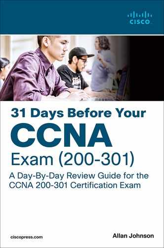
FHRPs enable you to install multiple routers in a subnet to collectively act as a single default router. These routers share a virtual IP address, as Figure 24-3 shows.
Figure 24-3 Redundant Default Gateway Example
In the figure, the G0/0 interfaces on R1 and R2 are configured with the IP addresses shown. However, both routers are also configured with the virtual IP address. This virtual IP address is the default gateway address configured on end devices. A redundancy protocol provides the mechanism for determining which router should take the active role in forwarding traffic. It also determines when a standby router must take over the forwarding role. The transition from one forwarding router to another is transparent to the end devices. This capability of a network to dynamically recover from the failure of a device acting as a default gateway is known as first-hop redundancy.
Regardless of which FHRP is implemented, the following steps take place when the active router fails:
Step 1. The standby router stops seeing hello messages from the forwarding router.
Step 2. The standby router assumes the role of the forwarding router.
Step 3. Because the new forwarding router assumes both the IP and MAC addresses of the virtual router, the end stations do not recognize a disruption in service.
FHRPs
The following list defines the three options available for FHRPs:
Hot Standby Router Protocol (HSRP): A Cisco-proprietary FHRP designed to allow for transparent failover of a first-hop IPv4 device. The function of the HSRP standby router is to monitor the operational status of the HSRP group and to quickly assume packet-forwarding responsibility if the active router fails. HSRP for IPv6 provides support for IPv6 networks.
Virtual Router Redundancy Protocol (VRRP): An IETF standard that dynamically assigns responsibility for one or more virtual routers to the VRRP routers on an IPv4 LAN. Its operation is similar to that of HSRP. VRRPv3 supports IPv4 and IPv6.
Gateway Load Balancing Protocol (GLBP): A Cisco-proprietary FHRP that protects data traffic from a failed router or circuit, as in HSRP and VRRP, while also allowing load balancing (also called load sharing) between a group of redundant routers. GLBP for IPv6 provides support for IPv6 networks.
The CCNA exam covers HSRP.
HSRP Operation
HSRP uses an active/standby model in which one router actively assumes the role of default gateway for devices on the subnet. One or more routers on the same subnet are then in standby mode. The HSRP active router implements a virtual IP address and matching virtual MAC address. This virtual IP address is part of the HSRP configuration and belongs to the same subnet as the physical interface IP address, but it is a different IP address. The router then automatically creates the virtual MAC address. All the cooperating HSRP routers know these virtual addresses, but only the HSRP active router uses these addresses at any one point in time.
Assume that you have two HSRP routers similar to R1 and R2 in Figure 24-3. These HSRP routers send each other messages to negotiate which router should be active. Then they continue to send each other messages so that the standby router can detect when the active router fails. If the active router fails, the standby router automatically assumes the virtual IP and MAC addresses and serves as the default gateway for the LAN. The new active router then sends out a gratuitous ARP so that the switches on the subnet will change their MAC address tables to reflect the correct port to reach the virtual MAC. This failover process is transparent to end devices, which are all configured with the virtual IP address as the default gateway.
So what about load balancing? Aren’t we wasting the capacity of the standby router and the links connecting to it? Yes, if the routers are connected to only one subnet. However, if VLANs are configured, the routers can share the load by each serving as the active router for some of the VLANs. For example, in Figure 24-3, R1 is the active router for VLAN 10, and R2 is the active router for VLAN 20. Both routers are configured with subinterfaces for inter-VLAN routing and the two virtual IP addresses so that each can assume the role of active router if the other router fails.
HSRP Versions
Cisco IOS defaults to HSRP version 1. Table 24-3 compares HSRP version 1 and version 2.
Table 24-3 HSRP Version 1 and Version 2 Features
HSRP Feature |
Version 1 |
Version 2 |
Group numbers supported |
0–255 |
0–4095 |
Authentication |
None |
MD5 |
Multicast addresses |
IPv4: 224.0.0.2 |
IPv4: 224.0.0.102 IPv6: FF02::66 |
Virtual MAC ranges |
0000.0C07.AC00 to 0000.0C07.ACFF |
IPv4: 0000.0C9F.F000 to 0000.0C9F.FFFF IPv6: 0005.73A0.0000 to 0005.73A0.0FFF |
HSRP Priority and Preemption
By default, the router with the numerically highest IPv4 address is elected as the active HSRP router. To configure a router to be the active router, regardless of IPv4 addressing, use the standby priority interface configuration command. The default priority is 100. The router with the highest priority will be the active HSRP router, assuming that no election has already occurred.
To force a new HSRP election, preemption must be enabled with the standby preempt interface configuration command.
HSRP Configuration and Verification
Let’s look at how to configure the topology in Figure 24-3. HSRP requires only one command on both routers:
Router(config-if)# standby group ip ip-address
The interface must be on the same subnet as the other HSRP router or routers. The group number and virtual ip-address must be the same on all HSRP routers.
Unless the priority command is used, the first router configured becomes the HSRP active router. Therefore, even though in Example 24-5 R1 is configured first, it includes a priority configuration to make sure that R1 is always the active router. Also, to make sure that R1 resumes the active router role after losing connectivity, the standby preempt command is configured.
Example 24-5 Configuring HSRP
R1(config)# interface g0/0
R1(config-if)# ip address 10.1.1.1 255.255.0.0
R1(config-if)# standby 1 ip 10.1.1.254
R1(config-if)# standby 1 priority 200
R1(config-if)# standby 1 preempt
R2(config)# interface g0/0
R2(config-if)# ip address 10.1.1.2 255.255.0.0
R2(config-if)# standby 1 ip 10.1.1.254
To verify that HSRP is up and running, use the show standby command or the brief version of the command, as in Example 24-6.
Example 24-6 Verifying HSRP
R1# show standby
GigabitEthernet0/0 - Group 1
  State is Active
    2 state changes, last state change 00:11:51
  Virtual IP address is 10.1.1.254
  Active virtual MAC address is 0000.0c07.ac01
   Local virtual MAC address is 0000.0c07.ac01 (v1 default)
  Hello time 3 sec, hold time 10 sec
   Next hello sent in 1.232 secs
  Preemption enabled
  Active router is local
  Standby router is 10.1.1.2, priority 100 (expires in 9.808 sec)
  Priority 200 (configured 200)
  Group name is "hsrp-Gi0/0-1" (default)
R1# show standby brief
                     P indicates configured to preempt.
                     |
Interface    Grp Pri P State   Active Standby   Virtual IP
Gi0/0        1   200   Active  local  10.1.1.2  10.1.1.254
R2# show standby
GigabitEthernet0/0 - Group 1
  State is Standby
     1 state change, last state change 00:15:23
  Virtual IP address is 10.1.1.254
  Active virtual MAC address is 0000.0c07.ac01
     Local virtual MAC address is 0000.0c07.ac01 (v1 default)
  Hello time 3 sec, hold time 10 sec
    Next hello sent in 1.008 secs
  Preemption disabled
  Active router is 10.1.1.1, priority 200 (expires in 8.624 sec)
  Standby router is local
  Priority 100 (default 100)
  Group name is "hsrp-Gi0/0-1" (default)
R2# show standby brief
                     P  indicates configured to preempt.
                     |
Interface    Grp Pri P State   Active    Standby  Virtual IP
Gi0/0        1   100   Standby 10.1.1.1   local    10.1.1.254
The show standby brief command displays the most pertinent information you might need in a few lines of output. The more verbose show standby command provides additional information, such as the number of state changes, the virtual MAC address, hellos, and the group name.
HSRP Load Balancing
As with STP, you might want your HSRP routers to be configured in active/active state, with one router active for one set of VLANs and the other router active for the remaining VLANs. Figure 24-4 shows a topology with multiple VLANs.
Figure 24-4 HSRP Load Balancing Example

To implement HSRP load balancing for different VLANs, configure R1 as the active router for half the VLANs and R2 as the active router for the other half of the VLANs (see Example 24-7).
Example 24-7 Configuring HSRP Load Balancing
R1# show run | begin interface G

interface GigabitEthernet0/0
  no ip address
  duplex auto
  speed auto
!
interface GigabitEthernet0/0.10
  encapsulation dot1Q 10
  ip address 10.1.10.1 255.255.255.0
  standby version 2
  standby 1 ip 10.1.10.254
  standby 1 priority 150
  standby 1 preempt
!
interface GigabitEthernet0/0.20
  encapsulation dot1Q 20
  ip address 10.1.20.1 255.255.255.0
  standby version 2
  standby 1 ip 10.1.20.254
R2# show run | begin interface G

interface GigabitEthernet0/0
  no ip address
  duplex auto
  speed auto
!
interface GigabitEthernet0/0.10
  encapsulation dot1Q 10
  ip address 10.1.10.2 255.255.255.0
  standby version 2
  standby 1 ip 10.1.10.254
!
interface GigabitEthernet0/0.20
  encapsulation dot1Q 20
  ip address 10.1.20.2 255.255.255.0
  standby version 2
  standby 1 ip 10.1.20.254
  standby 1 priority 150
  standby 1 preempt
!
To verify that HSRP with load balancing is operational, use the show standby command or the brief version of the command (see Example 24-8).
Example 24-8 Verifying HSRP Load Balancing
R1# show standby brief
                   P indicates configured to preempt.
                   |
Interface  Grp  Pri  P  State    Active     Standby      Virtual IP
           1    150     Active   local      10.1. 10.2   10.1.10.254
           1    100     Standby  10.1.20.2  local        10.1.20.254
R2# show standby brief
                    P indicates configured to preempt.
                    |
Interface   Grp  Pri  P  State    Active    Standby    Virtual IP
            1    100    Standby  10.1.10.1  local      10.1.20.254
            1    150    Active   local      10.1.20.1  10.1.20.254
Troubleshooting HSRP
Issues with HSRP most likely result from one or more of the following:
The active router that controls the virtual IP address for the group was not successfully elected.
The standby router did not successfully keep track of the active router.
No decision was made regarding when to hand another router control of the virtual IP for the group.
End devices failed to successfully configure the virtual IP address as the default gateway.
Common HSRP configuration issues include the following:
The HSRP routers are not connected to the same network segment.
The HSRP routers are not configured with IPv4 addresses from the same subnet.
The HSRP routers are not configured with the same virtual IPv4 address.
The HSRP routers are not configured with the same HSRP group number.
End devices are not configured with the correct default gateway address.
Study Resources
For today’s exam topics, refer to the following resources for more study.
Resource |
Module or Chapter |
Cisco Network Academy: CCNA 2 |
6 |
9 |
|
CCNA 200-301 Official Cert Guide, Volume 1 |
9 |
10 |
|
17 |
|
CCNA 200-301 Official Cert Guide, Volume 2 |
7 |
Portable Command Guide |
17 |