Day 6. QoS
CCNA 200-301 Exam Topics
Explain the forwarding per-hop behavior (PHB) for QoS such as classification, marking, queuing, congestion, policing, shaping
Key Topics
Today, we review quality of service (QoS), which refers to the tools and techniques network administrators can use to prioritize traffic on a network.
QoS
Normal default operation for switches and routers is to process frames and packets in the order in which they are received. This first-in, first-out (FIFO) queueing mechanism does not discriminate between traffic types.
QoS tools are used to classify traffic types based on the following four characteristics:
Latency (delay): Latency, or delay, is the amount of time it takes for data to be sent to the receiver. QoS tools can reduce the delay for time-sensitive packets, such as voice and video.
Jitter: Jitter is the variance in the delay of packets. QoS tools can even out the delay of packets to improve end-user experience.
Loss: Loss refers to the number of lost messages, usually as a percentage of the packets sent. QoS tools reduce packet loss, especially for time-sensitive traffic.
Bandwidth: Bandwidth is a measure of the amount of data an interface can send every second. QoS tools can manage which traffic type gets to use the bandwidth next and how much of the bandwidth each type of traffic gets over time.
Figure 6-1 list the three major traffic types. For voice and video, the minimum traffic characteristic values are shown.
Figure 6-1 Characteristics of Major Traffic Types

Figure 6-2 shows the sequence of QoS events as traffic is forwarded out an interface.
Figure 6-2 Overview of QoS Tools

QoS tools shown in Figure 6-2 include the following:
Classification and marking: QoS tools monitor traffic flows and classify packets based on the header contents. Messages are then marked by changing bits in the header.
Congestion avoidance: When traffic exceeds available network resources, some traffic might be selectively dropped, delayed, or re-marked to avoid congestion.
Congestion management: QoS tools manage the scheduling and shaping of traffic while packets wait their turn in a queue to exit the interface.
Classification and Marking
Classification refers to the process of matching fields in the headers to take some type of QoS action on the packet. These fields can include all the normal fields filtered by ACLs, as well as the Type of Service (ToS) field in an IPv4 packet or Traffic Class field in an IPv6 packet.
Marking refers to the process of changing bit values in the ToS or Traffic Class field. The contents of these two fields are identical, as Figure 6-3 shows.
Figure 6-3 The ToS and Traffic Class Fields in IPv4 and IPv6

Figure 6-3 highlights the Differentiated Services Code Point (DSCP) bits, which are the core of the Differentiated Services (DiffServ) model for QoS. QoS tools can use the 2 bits allotted for IP Explicit Congestion Notification (ECN) to inform downstream routers of congestion in the traffic flow.
DSCP and IPP
As standardized in RFC 2474, the 8 DSCP bits provide 64 different classifications that QoS can use. This is a vast improvement over the eight classifications allotted for the 3 bits in the previous IP Precedence (IPP) field (RFC 791). For backward compatibility, the DSCP bits include the Class Selector (CS) values that are designated to match the IPP bits, as in Figure 6-4.
Figure 6-4 The Class Selector Values

For Layer 2 trunk links, the third byte of the 4-byte 802.1Q header is reserved for Class of Service (CoS), and QoS tools can use it to mark frames. However, this field exists only as long as the frame is traversing trunk links, as Figure 6-5 shows. To continue the same level of service as traffic is routed on Layer 3, the ToS field must be marked.
Figure 6-5 CoS Marking Example

Additional fields that can be marked for QoS include the Traffic Identifier (TID) field in the 802.11 frame and the EXP field in MPLS. Table 6-1 lists all the QoS fields.
Table 6-1 QoS Marking Fields
Field |
Name Header(s) |
Length (bits) |
Where Used |
DSCP |
IPv4, IPv6 |
6 |
End-to-end packet |
IPP |
IPv4, IPv6 |
3 |
End-to-end packet |
CoS |
802.1Q |
3 |
Over VLAN trunk |
TID |
802.11 |
3 |
Over Wi-Fi |
EXP |
MPLS Label |
3 |
Over MPLS WAN |
EF and AF
Expedited Forwarding (EF) is a single DSCP decimal value of 46 that is suggested for use with packets that require low latency, low jitter, and low loss. QoS implementations typically use EF to mark voice packets.
Assured Forwarding (AF), specified in RFC 2597, defines a set of 12 DSCP values that are arranged in a matrix, as in Figure 6-6.
Figure 6-6 AF DSCP Values

The four rows in Figure 6-6 show the queue priorities. The three columns show the drop priority. The AF names follow the format AFXY, where X refers to the queue and Y refers to the drop priority.
Congestion Management
Congestion management refers to the QoS tools used to manage queues as packets wait to exit an interface. Most networking devices can have a queuing system that can classify packets into multiple queues. A scheduler then decides which message to take next when the interface becomes available.
A popular tool is Class-Based Weighted Fair Queueing (CBWFQ), which assigns classes of traffic to queues and guarantees a minimum bandwidth for a queue. The scheduler then uses a round-robin algorithm to cycle through the queues in order, as in Figure 6-7.
Figure 6-7 CBWFQ Round-Robin Scheduling

However, CBWFQ alone does not satisfy the needs of the most time-sensitive traffic type during periods of heavy bandwidth congestion. Each voice call needs between 30 and 320 kbps, maximum delay of 150 ms, maximum jitter of 30 ms, and less than 1% packet loss. The solution is to add Low Latency Queueing (LLQ) to CBWFQ. The scheduler always takes the next voice packet from the LLQ, as Figure 6-8 shows.
Figure 6-8 Low Latency Queuing

Policing, Shaping, and TCP Discards
Two tools that can help manage and avoid congestion on heavily utilized links are policing and shaping. Although these tools are not commonly used throughout the enterprise, they are particularly helpful at the WAN edge. Both tools attempt to keep the bit rate at or below a specified speed. Policers drop packets, and shapers delay packets by placing them in a queue.
Policing makes sense at the WAN edge. For example, consider a Metro Ethernet WAN link that is contracted to allow no more than 200 Mbps, as in Figure 6-9.
Figure 6-9 WAN Edge with a CIR Below Link Speed
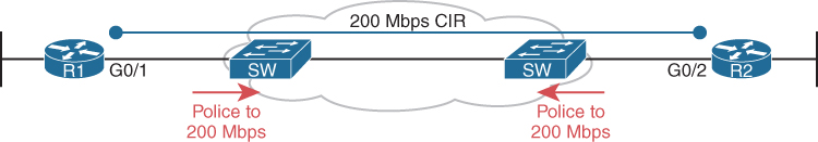
The service provider (SP) uses policing to match the Committed Information Rate (CIR). If the customer exceeds the 200-Mbps CIR, the SP can drop the excess packets or remark the excess packets but still allow them through. Later, the excess packets can be discarded if the SP’s network experiences congestion. Policing features include the following:
Measure traffic over time and compare to a configured policing rate
Allow for bursting traffic during slow times
Discard excess messages or remark for discard later if congestion occurs downstream
On the customer side of the link in Figure 6-9, the network administrator can use a shaper to slow traffic to match the 200-Mbps CIR. The shaper slows traffic by queuing packets and then scheduling packets based on the shaping rate, as Figure 6-10. shows.
Figure 6-10 Shaping with LLQ and CBWFQ

Shaping cannot slow the physical speed of an interface. Instead, it sends and waits. For example, with a 200-Mpbs CIR and a 1000-Mbps interface, the shaper sends traffic at 1000 Mbps 20% of the time. The other 80% of the time, the shaper is waiting.
This send–wait tactic can adversely impact time-sensitive voice and video traffic. Therefore, it is recommended that you set the time interval to 10 ms. Then the shaper will send 1000 Mbps for 2 ms and wait for 8 ms. This ensures that a voice packet will not have to wait more than 10 ms before being sent, which is well below the 150 ms maximum delay requirement.
The key features of shapers follow:
Measure traffic over time and compare it to a configured shaping rate
Allow for bursting traffic during slow times
Slow packets by queuing them and, over time, releasing them from the queue at the shaping rate
QoS and TCP
Without congestion-avoidance tools, tail drop can occur (see Figure 6-11).
Figure 6-11 Tail Drop Example

As the lower queues fill up, the packets received last are dropped.
TCP’s connection-oriented services help QoS tools minimize tail drop. Recall that TCP uses a windowing process between sender and receiver to dynamically change the amount of data that is sent before an acknowledgment must be received. QoS tools can exploit this windowing feature by discarding some TCP segments before the queues fill. This forces the TCP connections to slow, reduces congestion, and avoids tail drop.
QoS tools monitor the depth of the queues over time. Configured thresholds specify what percentage of TCP packets should be dropped as the queue fills, as in Figure 6-12.
Figure 6-12 Queue Thresholds for Discarding TCP Packets

Study Resources
For today’s exam topics, refer to the following resources for more study.
Resource |
Module or Chapter |
Enterprise Networking, Security, and Automation |
9 |
CCNA 200-301 Official Cert Guide, Volume 2 |
11 |