Day 7. WAN, VPN, and IPsec
CCNA 200-301 Exam Topics
Describe characteristics of network topology architectures
Describe remote access and site-to-site VPNs
Key Topics
Today is a whirlwind review of WAN topologies, WAN connection options, virtual private networks (VPNs), and Internet Protocol Security (IPsec). Most of these exam topics are conceptual in nature and require no configuration skills, so read through this review several times and refer to your study resources for more in-depth review.
WAN Topologies
Figure 7-1 shows the four basic WAN topology options that a business can select for its WAN infrastructure:
Point-to-point: Typically uses a dedicated leased-line connection, such as T1/E1.
Hub-and-spoke: Offers a single-homed, point-to-multipoint topology in which a single interface on the hub router can be shared with multiple spoke routers through the use of virtual interfaces.
Full mesh: Gives each router a connection to every other router. Requires a large number of virtual interfaces.
Dual-homed: Provides redundancy for a single-homed hub-and-spoke topology by providing a second hub to connect to spoke routers.
A business can choose to implement a variety of these topologies. For example, an enterprise might choose to implement a full mesh topology between its regional headquarters. It might use a hub-and-spoke topology between regional headquarters and branch offices. If two of the branch offices communicate frequently, the network administrators might contract for a point-to-point link to reduce the traffic load on the hub routers. Using dual-homed connections to the Internet ensures that customers, partners, and teleworkers can always access the enterprise’s resources.
Figure 7-1 WAN Topology Options

WAN Connection Options
Many options for implementing WAN solutions are currently available. They differ in technology, speed, and cost. Figure 7-2 provides a high-level view of the various WAN link connection options. The following subsections describe these options in more detail.
Figure 7-2 WAN Link Connection Options

Dedicated Connection Options
Also called leased lines, dedicated connections are pre-established point-to-point WAN connections from the customer premises through the provider network to a remote destination (see Figure 7-3).
Figure 7-3 Leased Lines

Leased lines are usually more expensive than switched services because of the dedicated, always-on cost of providing WAN service to the customer. The dedicated capacity removes latency and jitter and provides a layer of security because only the customer’s traffic is allowed on the link. Table 7-1 lists the available leased line types and their bit-rate capacities.
Table 7-1 Leased Line Types and Capacities
Line Type |
Bit-Rate Capacity |
Line Type |
Bit-Rate Capacity |
56k |
56 kbps |
OC-9 |
466.56 Mbps |
64k |
64 kbps |
OC-12 |
622.08 Mbps |
T1 |
1.544 Mbps |
OC-18 |
933.12 Mbps |
E1 |
2.048 Mbps |
OC-24 |
1244.16 Mbps |
J1 |
2.048 Mbps |
OC-36 |
1866.24 Mbps |
E3 |
34.064 Mbps |
OC-48 |
2488.32 Mbps |
T3 |
44.736 Mbps |
OC-96 |
4976.64 Mbps |
OC-1 |
51.84 Mbps |
OC-192 |
9953.28 Mbps |
OC-3 |
155.54 Mbps |
OC-768 |
39,813.12 Mbps |
Circuit-Switched Connection Options
The two main types of circuit-switched connections are analog dialup and ISDN. Both technologies have limited implementation bases in today’s networks. However, they are both still used in remote rural areas and other areas of the globe where more recent technologies are not yet available.
Analog dialup uses modems at very low-speed connections that might be adequate for the exchange of sales figures, prices, routine reports, and email, or as an emergency backup link.
ISDN turns the local loop into a TDM digital connection, which enables it to carry digital signals that result in higher-capacity switched connections than are available with analog modems. Two types of ISDN interfaces exist:
Basic Rate Interface (BRI): Provides two 64-kbps B-channels for voice or data transfer and a 16-kbps D-channel for control signaling.
Primary Rate Interface (PRI): Provides 23 B-channels with 64 kbps and 1 D-channel with 64 kbps in North America, for a total bit rate of up to 1.544 Mbps. Europe uses 30 B-channels and 1 D-channel, for a total bit rate of up to 2.048 Mbps.
Figure 7-4 illustrates the various differences between ISDN BRI and PRI lines.
Figure 7-4 ISDN Network Infrastructure and PRI/BRI Line Capacity

Packet-Switched Connection Options
The most common packet-switching technologies used in today’s enterprise WANs include Metro Ethernet and MPLS. Legacy technologies include X.25 and ATM.
Metro Ethernet
Metro Ethernet (MetroE) uses IP-aware Ethernet switches in the service provider’s network cloud to offer enterprises converged voice, data, and video services at Ethernet speeds. Consider some benefits of Metro Ethernet:
Reduced expenses and administration: Enables businesses to inexpensively connect numerous sites in a metropolitan area to each other and to the Internet without the need for expensive conversions to ATM or Frame Relay
Easy integration with existing networks: Connects easily to existing Ethernet LANs
Enhanced business productivity: Enables businesses to take advantage of productivity-enhancing IP applications that are difficult to implement on TDM or Frame Relay networks, such as hosted IP communications, VoIP, and streaming and broadcast video
MPLS
Multiprotocol Label Switching (MPLS) has the following characteristics:
Multiprotocol: MPLS can carry any payload, including IPv4, IPv6, Ethernet, ATM, DSL, and Frame Relay traffic.
Labels: MPLS uses labels inside the service provider’s network to identify paths between distant routers instead of between endpoints.
Switching: MPLS actually routes IPv4 and IPv6 packets, but everything else is switched.
As Figure 7-5 shows, MPLS supports a wide range of WAN technologies, including serial leased lines, Metro Ethernet, ATM, Frame Relay, and DSL (not shown).
Figure 7-5 Popular MPLS Connection Options

In Figure 7-5, CE refers to the customer edge routers. PE is the provider edge routers that add and remove labels.
Internet Connection Options
Broadband connection options typically are used to connect telecommuting employees to a corporate site over the Internet. These options include Digital Subscriber Line (DSL), cable, and wireless.
DSL
DSL technology, shown in Figure 7-6, is an always-on connection technology that uses existing twisted-pair telephone lines to transport high-bandwidth data and provides IP services to subscribers.
Figure 7-6 Teleworker DSL Connection

Current DSL technologies use sophisticated coding and modulation techniques to achieve data rates of up to 8.192 Mbps. A variety of DSL types, standards, and emerging technologies exist. DSL is a popular choice for enterprise IT departments to support home workers.
Cable Modem
A cable modem provides an always-on connection and simple installation. Figure 7-7 shows how a subscriber connects a computer or LAN router to the cable modem, which translates the digital signals into the broadband frequencies used for transmitting on a cable television network.
Figure 7-7 Teleworker Cable Modem Connection

Wireless
In the past, the main limitation of wireless access was the need to be within range of a wireless router or a wireless modem with a wired connection to the Internet; however, the following wireless technologies enable users to connect to the Internet from almost any location:
Municipal Wi-Fi: Many cities have begun setting up municipal wireless networks. Some of these networks provide high-speed Internet access for free or for substantially less than the price of other broadband services.
WiMAX: Worldwide Interoperability for Microwave Access (WiMAX) is an IEEE 802.16 technology that is just beginning to come into use. It provides high-speed broadband service with wireless access and provides broad coverage similar to a cell phone network instead of through small Wi-Fi hotspots.
Satellite Internet: This technology is typically used in rural areas where cable and DSL are unavailable.
Cellular service: Cellular service is an option for connecting users and remote locations where no other WAN access technology is available. Common cellular access methods include 3G/4G (third generation and fourth generation) and Long-Term Evolution (LTE) cellular access.
Choosing a WAN Link Option
Table 7-2 compares the advantages and disadvantages of the various WAN connection options reviewed.
Table 7-2 Choosing a WAN Link Connection
Option |
Description |
Advantages |
Disadvantages |
Sample Protocols |
Leased line |
Point-to-point connection between two LANs. |
Most secure |
Expensive |
PPP, HDLC, SDLC |
Circuit switching |
Dedicated circuit path created between endpoints. The best example is dialup connections. |
Inexpensive |
Call setup |
PPP, ISDN |
Packet switching |
Devices transporting packets via a shared single point-to-point or point-to-multipoint link across a carrier internetwork. Variable-length packets are transmitted over PVCs or SVCs. |
Highly efficient use of bandwidth |
Shared media across link |
Frame Relay, MetroE |
Internet |
Connectionless packet switching using the Internet as the WAN infrastructure. Uses network addressing to deliver packets. Because of security issues, VPN technology must be used. |
Least expensive, globally available |
Least secure |
DSL, cable modem, wireless |
VPN Technology
A virtual private network (VPN) is an encrypted connection between private networks over a public network such as the Internet. Instead of using a dedicated Layer 2 connection such as a leased line, a VPN uses virtual connections called VPN tunnels, which are routed through the Internet from the company’s private network to the remote site or employee host.
VPN Benefits
Benefits of VPN include the following:
Cost savings: Eliminates the need for expensive dedicated WAN links and modem banks
Security: Uses advanced encryption and authentication protocols that protect data from unauthorized access
Scalability: Can add large amounts of capacity without adding significant infrastructure
Compatibility with broadband technology: Supported by broadband service providers, so mobile workers and telecommuters can take advantage of their home high-speed Internet service to access their corporate networks
Types of VPN Access
The following describes the types of VPN access methods:
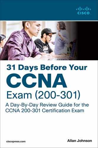
Site-to-site VPNs: Site-to-site VPNs connect entire networks to each other. For example, a site-to-site VPN can connect a branch office network to a company headquarters network, as in Figure 7-8. Each site is equipped with a VPN gateway, such as a router, firewall, VPN concentrator, or security appliance. In the figure, a remote branch office uses a site-to-site VPN to connect with the corporate head office.
Figure 7-8 Site-to-Site VPNs

Remote-access VPNs: Remote-access VPNs enable individual hosts, such as telecommuters, mobile users, and extranet consumers, to access a company network securely over the Internet, as in Figure 7-9. Each host typically has client software for a client-based VPN connection or uses a web browser for clientless VPN connection. Web-based clientless VPNs are also typically called clientless Secure Sockets Layer (SSL) connections. However, the VPN is actually established using Transport Layer Security (TLS). TLS is the newer version of SSL and is sometimes expressed as SSL/TLS.
Figure 7-9 Remote-Access VPNs
Generic Routing Encapsulation (GRE): A standard IPsec VPN (non-GRE) can only create secure tunnels for unicast traffic. GRE is a nonsecure site-to-site VPN tunneling protocol that can support multicast and broadcast traffic needed for network layer protocols. However, GRE does not by default support encryption; therefore, it does not provide a secure VPN tunnel. To solve this problem, you can encapsulate routing protocol traffic by using a GRE packet and then encapsulate the GRE packet into an IPsec packet to forward it securely to the destination VPN gateway. The terms used to describe the encapsulation of GRE over IPsec tunnel are passenger protocol for the routing protocol, carrier protocol for GRE, and transport protocol for IPsec, as shown in Figure 7-10.
Figure 7-10 Transport, Carrier, and Passenger Protocols

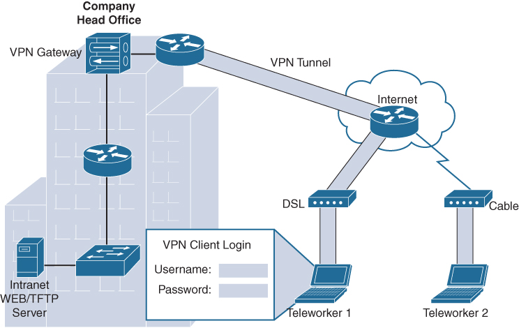
Dynamic Multipoint VPN (DMVPN): DMVPN is a Cisco-proprietary solution for building many VPNs in an easy, dynamic, and scalable manner. DMVPN allows a network administrator to dynamically form hub-to-spoke tunnels and spoke-to-spoke tunnels, as in Figure 7-11. DMVPN simplifies the VPN tunnel configuration and provides a flexible option for connecting a central site with branch sites. It uses a hub-and-spoke configuration to establish a full mesh topology. Spoke sites establish secure VPN tunnels with the hub site. Each site is configured using Multipoint Generic Routing Encapsulation (mGRE). The mGRE tunnel interface allows a single GRE interface to dynamically support multiple IPsec tunnels.
Figure 7-11 DMVPN Sample Topology
DMVPN uses the following technologies:
Next Hop Resolution Protocol (NHRP): Maps public IP addresses for all tunnel spokes
IPsec encryption: Provides the security to transport private information over public networks
mGRE: Allows a single interface to support multiple IPsec tunnels
IPsec Virtual Tunnel Interface (VTI): Like DMVPN, VTI simplifies the configuration process required to support multiple sites and remote access. IPsec VTI is capable of sending and receiving both IP unicast and multicast encrypted traffic. Therefore, routing protocols are automatically supported without the need to configure GRE tunnels.
Service provider MPLS VPNs: MPLS can provide clients with managed VPN solutions; therefore, securing traffic between client sites is the responsibility of the service provider. Two types of MPLS VPN solutions are supported by service providers:
Layer 3 MPLS VPN: The service provider participates in customer routing, redistributing the routes through the MPLS network to the customer’s remote locations.
Layer 2 MPLS VPN: The service provider is not involved in the customer routing. Instead, the provider deploys Virtual Private LAN Service (VPLS) to emulate an Ethernet multiaccess LAN segment over the MPLS network. No routing is involved. The customer’s routers effectively belong to the same multiaccess network.
VPN Components
Figure 7-12 illustrates a typical VPN topology. Components required to establish this VPN include the following:
An existing enterprise network with servers and workstations
A connection to the Internet
VPN gateways, such as routers, firewalls, VPN concentrators, and Adaptive Security Appliances (ASAs), that act as endpoints to establish, manage, and control VPN connections
Appropriate software to create and manage VPN tunnels
Figure 7-12 VPN Components

Establishing Secure VPN Connections
VPNs secure data by encapsulating and encrypting it. With regard to VPNs, encapsulation and encryption are defined as follows:
Encapsulation is also called tunneling because encapsulation transmits data transparently from source network to destination network through a shared network infrastructure.
Encryption codes data into a different format by using a secret key, which is then used on the other side of the connection for decryption.
VPN Tunneling
Tunneling uses three classes of protocols:
Carrier protocol: The protocol over which information travels, such as Frame Relay, PPP, or MPLS
Encapsulating protocol: The protocol that is wrapped around the original data, such as GRE, IPsec, L2F, PPTP, or L2TP
Passenger protocol: The protocol over which the original data was carried, such as IPX, AppleTalk, IPv4, or IPv6
Figure 7-13 illustrates an email message traveling through the Internet over a VPN connection.

Figure 7-13 Packet Encapsulation in a VPN Tunnel
VPN Encryption Algorithms
The degree of security provided by any encryption algorithm depends on the key’s length. Some of the most common encryption algorithms and the lengths of the keys they use are as follows:
Data Encryption Standard (DES) algorithm: Uses a 56-bit key and ensures high-performance encryption. DES is a symmetric key cryptosystem.
Triple DES (3DES) algorithm: A newer variant of DES that encrypts with one key, decrypts with a different key, and then encrypts a final time with another key.
Advanced Encryption Standard (AES): Provides stronger security than DES and is computationally more efficient than 3DES. AES offers three key lengths: 128-, 192-, and 256-bit keys.
Rivest, Shamir, and Adleman (RSA): An asymmetric key cryptosystem. The keys use a bit length of 512, 768, 1024, or larger.
With symmetric encryption, the encryption key and decryption key are the same. With asymmetric encryption, they are different.
Hashes
VPNs use a keyed hashed message authentication code (HMAC) data-integrity algorithm to guarantee a message’s integrity and authenticity without any additional mechanisms.
The cryptographic strength of the HMAC depends on the cryptographic strength of the underlying hash function, the key’s size and quality, and the size of the hash output length, in bits. There are two common HMAC algorithms:
Message Digest 5 (MD5): Uses a 128-bit shared secret key
Secure Hash Algorithm 1 (SHA-1): Uses a 160-bit secret key
Figure 7-14 shows an example using MD5 as the HMAC algorithm.
Figure 7-14 Creating and Verifying a Message Digest

An HMAC has two parameters: a message input and a shared secret key known only to the message originator and intended recipients. In Figure 7-14, both R1 and R2 know the shared secret key. The process in Figure 7-1. uses the following steps:
Step 1. R1 uses MD5 to perform the hashing function, which outputs a hash value. This hash value is then appended to the original message and sent to R2.
Step 2. R2 removes the hash value from the original message, runs the same hash operation, and then compares its hash value with the hash value sent by R1. If the two hashes match, data integrity has not been compromised.
VPN Authentication
The device on the other end of the VPN tunnel must be authenticated before the communication path is considered secure. The two peer authentication methods are as follows:
Pre-Shared Key (PSK): A secret key is shared between the two parties using a secure channel before it needs to be used.
RSA signature: This method uses the exchange of digital certificates to authenticate the peers.
IPsec Security Protocols
Both IPsec and SSL VPN technologies offer access to virtually any network application or resource. However, when security is an issue, IPsec is the superior choice. Table 7-3 compares IPsec and SSL remote access deployments.
Table 7-3 IPsec and SSL for Remote Access
Feature |
IPsec |
SSL |
Applications supported |
Extensive—All IP-based applications are supported. |
Limited—Only web-based applications and file sharing are supported. |
Authentication strength |
Strong—Uses two-way authentication with shared keys or digital certificates. |
Moderate—Using one-way or two-way authentication. |
Encryption strength |
Strong—Uses key lengths from 56 bits to 256 bits. |
Moderate to strong—With key lengths from 40 bits to 256 bits. |
Connection complexity |
Medium—Requires that a VPN client be pre-installed on a host. |
Low—Requires a web browser only on a host. |
Connection option |
Limited—Only specific devices with specific configurations can connect. |
Extensive—Any device with a web browser can connect. |
IPsec spells out the messaging necessary to secure VPN communications but relies on existing algorithms. The two main IPsec framework protocols are as follows:
Authentication Header (AH): Used when confidentiality is not required or permitted. AH provides data authentication and integrity for IP packets passed between two systems. It verifies the originators of any messages and that any message passed has not been modified during transit. AH does not provide data confidentiality (encryption) of packets. Used alone, the AH protocol provides weak protection. Consequently, it is used with the ESP protocol to provide data encryption and tamper-aware security features.
Encapsulating Security Payload (ESP): Provides confidentiality and authentication by encrypting the IP packet. Although both encryption and authentication are optional in ESP, at a minimum, one of them must be selected.
IPsec relies on existing algorithms to implement encryption, authentication, and key exchange. Figure 7-1. shows how IPsec is structured.
IPsec provides the framework, and the administrator chooses the algorithms used to implement the security services within that framework. As Figure 7-1. illustrates, the administrator must fill the four IPsec framework squares:
Choose an IPsec protocol.
Choose the encryption algorithm that is appropriate for the desired level of security.
Choose an authentication algorithm to provide data integrity.
The last square is the Diffie-Hellman (DH) algorithm group, which establishes the sharing of key information between peers. Choose which group to use: DH1, DH2, or DH5.
Figure 7-15 IPsec Framework

Study Resources
For today’s exam topics, refer to the following resources for more study.
Resource |
Module or Chapter |
Cisco Network Academy: CCNA 3 |
7 |
|
8 |
CCNA 200-301 Official Cert Guide, Volume 2 |
14 |