Day 12. Fine-Tuning and Troubleshooting OSPF
CCNA 200-125 Exam Topics
Configure and verify single-area OSPFv2
Key Topics
Today’s review focuses on fine-tuning and troubleshooting OSPFv2. Fine-tuning OSPF involves modifying timers, conducting DR/BDR elections, and propagating a default route. We also turn our focus to troubleshooting the OSPF process.
OSPFv2 Configuration Example
To fine-tune OSPFv2, we use the topology in Figure 12-1 and the addressing scheme in Table 12-1.
Figure 12-1 OSPFv2 Configuration Topology

Table 12-1 Addressing Scheme for OSPFv2
Device |
Interface |
IP Address |
Subnet Mask |
R1 |
G0/0 |
172.16.1.1 |
255.255.255.0 |
|
S0/0/0 |
172.16.3.1 |
255.255.255.252 |
|
S0/0/1 |
192.168.10.5 |
255.255.255.252 |
|
S0/1/0 |
209.165.200.226 |
255.255.255.224 |
R2 |
G0/0 |
172.16.2.1 |
255.255.255.0 |
|
S0/0/0 |
172.16.3.2 |
255.255.255.252 |
|
S0/0/1 |
192.168.10.9 |
255.255.255.252 |
R3 |
G0/0 |
192.168.1.1 |
255.255.255.0 |
|
S0/0/0 |
192.168.10.6 |
255.255.255.252 |
|
S0/0/1 |
192.168.10.10 |
255.255.255.252 |
Example 12-1 shows the network commands for all three routers to enable OSPFv2 on all interfaces.
Example 12-1 Configuring OSPF Networks
R1(config)# router ospf 10
R1(config-router)# router-id 1.1.1.1
R1(config-router)# network 172.16.1.0 0.0.0.255 area 0
R1(config-router)# network 172.16.3.0 0.0.0.3 area 0
R1(config-router)# network 192.168.10.4 0.0.0.3 area 0
R1(config-router)# passive-interface g0/0
R1(config-router)# auto-cost reference-bandwidth 10000
R1(config-router)# interface S0/0/1
R1(config-if)# bandwidth 64
R2(config)# router ospf 10
R2(config-router)# router-id 2.2.2.2
R2(config-router)# network 172.16.2.0 0.0.0.255 area 0
R2(config-router)# network 172.16.3.0 0.0.0.3 area 0
R2(config-router)# network 192.168.10.8 0.0.0.3 area 0
R2(config-router)# passive-interface g0/0
R2(config-router)# auto-cost reference-bandwidth 10000
R2(config-router)# interface S0/0/1
R2(config-if)# bandwidth 1024
R3(config)# router ospf 10
R3(config-router)# router-id 3.3.3.3
R3(config-router)# network 192.168.1.0 0.0.0.255 area0
R3(config-router)# network 192.168.10.4 0.0.0.3 area 0
R3(config-router)# network 192.168.10.8 0.0.0.3 area 0
R3(config-router)# passive-interface g0/0
R3(config-router)# auto-cost reference-bandwidth 10000
R3(config-router)# interface S0/0/0
R3(config-if)# bandwidth 64
R3(config-if)# interface S0/0/1
R3(config-if)# bandwidth 1024
Modifying OSPFv2
This section reviews concepts related to and commands for redistributing a default route, tuning OSPF interfaces, and manipulating the designated router/backup designated router (DR/BDR) election process.
Redistributing a Default Route
In Figure 12-1, R1 has a link to the Internet that makes R1 an autonomous system boundary router (ASBR). We therefore configure a default route to the Internet and redistribute the default static route to R2 and R3 with the default-information originate command, as in Example 12-2.
Example 12-2 ASBR Static Default Route Configuration
R1(config)# ip route 0.0.0.0 0.0.0.0 Serial 0/1/0
R1(config)# router ospf 10
R1(config-router)# default-information originate
Both R2 and R3 should now have default routes identified with the O*E2 code, as in Example 12-3.
Example 12-3 R2 and R3 OSPF Routes with Default Route
R2# show ip route ospf
     172.16.0.0/16 is variably subnetted, 5 subnets, 3 masks
O       172.16.1.0 [110/6477] via 172.16.3.1, 00:02:45, Serial0/0/0
O    192.168.1.0 [110/6486] via 192.168.10.10, 00:00:55, Serial0/0/1
     192.168.10.0/24 is variably subnetted, 3 subnets, 2 masks
O       192.168.10.4 [110/12952] via 192.168.10.10, 00:00:55, Serial0/0/1
O*E2 0.0.0.0/0 [110/1] via 172.16.3.1, 00:00:09, Serial0/0/0
R3# show ip route ospf
     172.16.0.0/16 is variably subnetted, 3 subnets, 2 masks
O      172.16.1.0 [110/6477] via 192.168.10.5, 00:26:01, Serial0/0/0
O      172.16.2.0 [110/6486] via 192.168.10.9, 00:26:01, Serial0/0/1
O      172.16.3.0 [110/6540] via 192.168.10.5, 00:26:01, Serial0/0/0
O*E2 0.0.0.0/0 [110/1] via 192.168.10.9, 00:01:19, Serial0/0/1
Modifying Hello and Dead Intervals
The default hello interval on multiaccess and point-to-point networks is 10 seconds. Nonbroadcast multiaccess (NBMA) networks default to a 30-second hello interval. The default dead interval is four times the hello interval.
It might be desirable to change the OSPF timers so that routers detect network failures in less time. Doing this increases traffic, but sometimes a need for quick convergence outweighs the extra traffic.
You can modify OSPF hello and dead intervals manually by using the following interface commands:
Router(config-if)# ip ospf hello-interval seconds
Router(config-if)# ip ospf dead-interval seconds
Although the dead interval defaults to four times the hello interval and does not have to be explicitly configured, it is a good practice to document the new dead interval in the configuration. Example 12-4 shows the hello interval and dead interval modified to 5 seconds and 20 seconds, respectively, on the Serial 0/0/0 interface for R1.
Example 12-4 Modifying Hello and Dead Intervals on R1
R1(config)# interface serial 0/0/0
R1(config-if)# ip ospf hello-interval 5
R1(config-if)# ip ospf dead-interval 20
R1(config-if)# end
Remember that, unlike with Enhanced Interior Gateway Routing Protocol (EIGRP), with OSPF hello and dead intervals must be equivalent between neighbors. Therefore, R2 should be configured with the same intervals as R1.
OSPF Network Types
OSPF defines five network types:
Point-to-point: Two routers interconnected over a common link. No other routers are on the link. This is often the configuration in WAN links.
Broadcast multiaccess: Multiple routers interconnected over an Ethernet network.
NBMA: Multiple routers interconnected in a network that does not allow broadcasts, such as Frame Relay.
Point-to-multipoint: Multiple routers interconnected in a hub-and-spoke topology over an NBMA network. Often used to connect branch sites (spokes) to a central site (hub).
Virtual links: Special OSPF network used to interconnect distant OSPF areas to the backbone area.
Multiaccess networks create two challenges for OSPF regarding the flooding of LSAs:
Creation of multiple adjacencies: Ethernet networks can potentially interconnect many OSPF routers over a common link. Using the formula n(n – 1) / 2, where n equals the number of routers, 5 routers would require 10 separate neighbor adjacencies; 10 routers would require 45.
Extensive flooding of LSAs: Link-state routers flood their link-state packets when OSPF is initialized or when the topology changes. This flooding can become excessive without a mechanism to reduce the number of adjacencies.
DR/BDR Election
The solution to managing the number of adjacencies and the flooding of LSAs on a multiaccess network is the designated router (DR). To reduce the amount of OSPF traffic on multiaccess networks, OSPF elects a DR and backup DR (BDR). The DR is responsible for updating all other OSPF routers when a change occurs in the multiaccess network. The BDR monitors the DR and takes over as DR if the current DR fails.
The following criteria are used to elect the DR and BDR:
The DR is the router with the highest OSPF interface priority.
The BDR is the router with the second-highest OSPF interface priority.
If OSPF interface priorities are equal, the highest router ID breaks the tie.
When the DR is elected, it remains the DR until one of the following conditions occurs:
The DR fails.
The OSPF process on the DR fails.
The multiaccess interface on the DR fails.
If the DR fails, the BDR assumes the role of DR, and an election is held to choose a new BDR. If a new router enters the network after the DR and BDR have been elected, it will not become the DR or the BDR even if it has a higher OSPF interface priority or router ID than the current DR or BDR. The new router can be elected the BDR if the current DR or BDR fails. If the current DR fails, the BDR becomes the DR, and the new router can be elected the new BDR.
Without additional configuration, you can control the routers that win the DR and BDR elections by doing either of the following:
Boot the DR first, followed by the BDR, and then boot all other routers.
Shut down the interface on all routers and then issue no shutdown on the DR, then the BDR, and then all other routers.
The recommended way to control DR/BDR elections, however, is to change the interface priority.
Controlling the DR/BDR Election
Because the DR becomes the focal point for the collection and distribution of LSAs in a multiaccess network, this router must have sufficient CPU and memory capacity to handle the responsibility. Instead of relying on the router ID to decide which routers are elected the DR and BDR, it is better to control the election of these routers with the ip ospf priority interface command:
Router(config-if)# ip ospf priority {0 - 255}
The priority value defaults to 1 for all router interfaces, which means the router ID determines the DR and BDR. If you change the default value from 1 to a higher value, however, the router with the highest priority becomes the DR, and the router with the next highest priority becomes the BDR. A value of 0 makes the router ineligible to become a DR or BDR.
All the routers in Figure 12-2 booted at the same time with a complete OSPF configuration. In such a situation, R3 is elected the DR, and R2 is elected the BDR, based on the highest router IDs, as you can see in the output for the neighbor table on R1 in Example 12-5.
Figure 12-2 Multiaccess Topology

Example 12-5 Verifying the DR and BDR
R1# show ip ospf neighbor
Neighbor ID  Pri  State     Dead Time Address     Interface
2.2.2.2        1  FULL/BDR  00:00:32  192.168.1.2 GigabitEthernet0/0
3.3.3.3        1  FULL/DR   00:00:38  192.168.1.3 GigabitEthernet0/0
R1#
Assume that R1 is the better candidate to be DR and that R2 should be BDR. Example 12-6 shows a way to control the DR/BDR election in the topology in Figure 12-2.
Example 12-6 Modifying the OSPF Interface Priority
R1(config)# interface gigabitethernet 0/0
R1(config-if)# ip ospf priority 200
R2(config)# interface gigabitethernet 0/0
R2(config-if)# ip ospf priority 100
Notice that we changed both routers. Although R2 was the BDR without doing anything, it would lose this role to R3 if we had not configured R2’s priority to be higher than the default.
Before R1 can become DR, the OSPF process needs to restart. We can make this happen by shutting down the interfaces or simply by entering the clear ip ospf process command in privileged EXEC mode, as in Example 12-7. The neighbor table on R3 shows that R1 is now the DR, and R2 is the BDR.
Example 12-7 Restarting the OSPF Process and Verifying New DR and BDR
R1# clear ip ospf process
Reset ALL OSPF processes? [no]: y
R1#
R2# clear ip ospf process
Reset ALL OSPF processes? [no]: y
R2#
R3# clear ip ospf process
Reset ALL OSPF processes? [no]: y
R2#
R3# show ip ospf neighbor

Neighbor ID Pri  State     Dead Time  Address     Interface
2.2.2.2     100  FULL/BDR  00:00:38   192.168.1.2 GigabitEthernet0/0
1.1.1.1     200  FULL/DR   00:00:30   192.168.1.1 GigabitEthernet0/0
R3#
Troubleshooting OSPF
Understanding how OSPF operates is fundamental to troubleshooting any OSPF issues. Key to this understanding is the concept of the states OSPF transitions through on its way to adjacency with a neighbor.
OSPF States
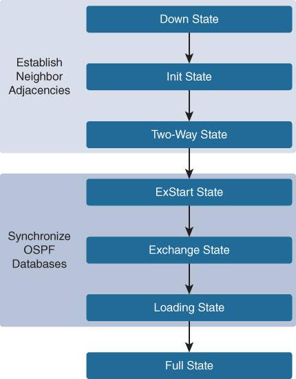
Figure 12-3 lists the OSPF states. When troubleshooting OSPF neighbors, be aware that the FULL and TWO-WAY states are normal. All other states are transitory.
Figure 12-3 Transitioning Through the OSPF States
OSPF Adjacency
Lack of adjacency is a common issue in OSPF troubleshooting because the two OSPF neighbors must agree on several settings. OSPF adjacencies do not form for several reasons:
The interfaces are not on the same network.
OSPF network types do not match.
OSPF hello or dead timers do not match.
The interface to the neighbor is incorrectly configured as passive.
An OSPF network command is missing or incorrect.
Authentication is misconfigured.
OSPF Troubleshooting Commands
When trying to isolate an OSPFv2 routing issue, the following commands are useful:
show ip protocols: Verifies vital OSPF configuration information, including the OSPF process ID, the router ID, networks the router is advertising, neighbors the router is receiving updates from, and the default administrative distance, which is 110 for OSPF.
show ip ospf neighbor: Verifies that the router has formed an adjacency with its neighboring routers.
show ip ospf interface: Displays the OSPF parameters configured on an interface, such as the OSPF process ID, area, cost, and timer intervals.
show ip ospf: Examines the OSPF process ID and router ID. This command also displays the OSPF area information and the last time the SPF algorithm was calculated.
show ip route ospf: Displays only the OSPF learned routes in the routing table.
clear ip ospf process: Resets the OSPFv2 neighbor adjacencies.
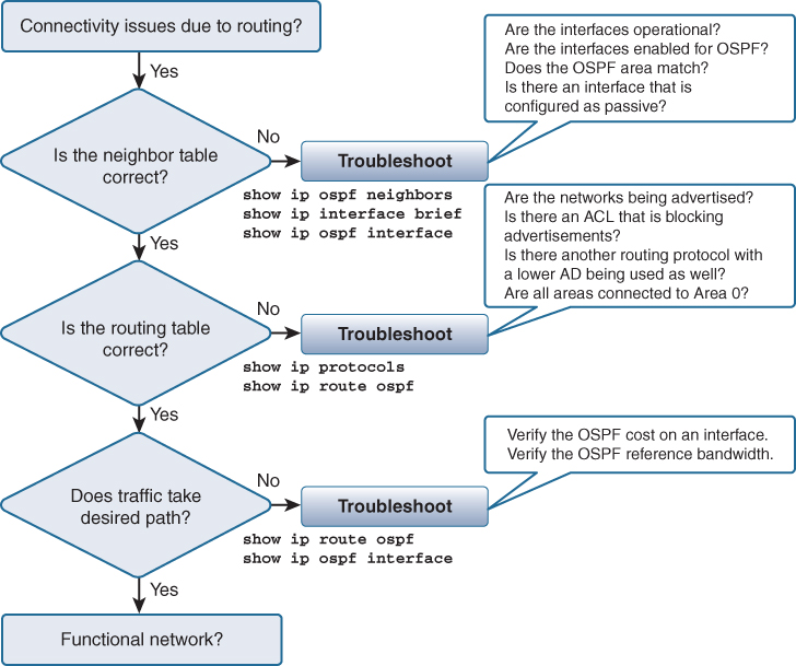
Figure 12-4 illustrates a method for using these commands in a systematic way.
Figure 12-4 Systematic Method for Troubleshooting OSPFv2
Study Resources
For today’s exam topics, refer to the following resources for more study.
Resource |
Module or Chapter |
Enterprise Networking, Security, and Automation |
2 |
CCNA 200-301 Official Cert Guide, Volume 1 |
20 |
Portable Command Guide |
16 |