Chapter 6
Holography for 3D Displays
Recording media such as photographic films, emulsions, photo-polymers, and also CCDs and LCDs are only able to store intensities of light and not the phase of a light wave. Also, the human eye is only receptive to intensity. D. Gabor [1–3] used the interference of two mutually coherent light waves with different phase angles and the resulting interference pattern to record intensity and phase. The phases, as we shall see, are expressed by a modulation of this pattern. The whole information on beams of light, the magnitude and the phase, is contained in this interference pattern. In Greek holos means whole, from which the denotation hologram for that pattern is derived.
If one of the mutually coherent light waves represents the light reflected and diffracted from a 2D or 3D object and the other light wave, the reference beam, exhibits a known amplitude and phase, then the hologram contains the whole information on the object, even if it happens to be a 3D object. The 3D image can be reconstructed by shining the reference beam or a beam related to it onto the hologram and by perceiving the diffraction beam. That way, the reference beam serves as a reading beam, whereas during the recording of the hologram it was a writing beam. The reconstructed image is a true 3D image in space which the viewer can look at from various perspectives.
The images will be projected by lenses. As lenses are able to perform the inverse Fourier transform, holograms can also be stored directly as a Fourier transform. When the hologram is read out onto a lens, that lens provides the original image. This opens up the way for computer-generated holograms, where computers perform the algorithm for the fast Fourier transform (FFT) of an image. The data for the FFT has to be in digital form. Digital holography is presently applied in medicine, microscopy, and scientific applications. However, work is going on to render it available for consumer applications also, such as mobile devices or TV. The problem is to achieve real-time processing resulting in a 3D TV image.
6.2 Recording a Hologram and Reconstruction of the Original 3D Image
The investigation of recording and reconstruction will be carried out with phasors. To electrical engineers and from optics they are known as a complex representation of a voltage, a current, or a point in an electromagnetic field, by the magnitude and the phase. An excellent description of holography by phasors can be found in [4], p. 297. For a field of light the phasor is
for a point x, y in a plane perpendicular to the direction of a propagating wave, where ![]() is the magnitude and its square the intensity of light.
is the magnitude and its square the intensity of light.
In our application a(x, y) belongs to a wave reflected and diffracted from an object. The reference beam has the phasor
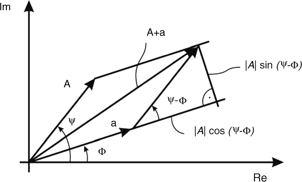
The waves a(x, y) and A(x, y) are schematically drawn in Figure 6.1, where they interfere in the plane of a recording medium. For a given point x, y the two complex numbers a(x, y) and A(x, y), drawn in a complex plane, are shown in Figure 6.2, with the real part Re and the imaginary part Im as axes. The sum a + A of the two complex numbers as shown in Figure 6.2 contains the square of the magnitude, which is the intensity I of the interference pattern
![]()
or
Figure 6.1 The image wave a(x, y) and the reference wave A(x, y) interfering on the recording medium.
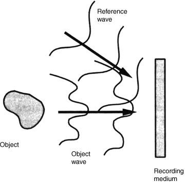
Figure 6.2 The addition of the two phasors a and A and the magnitude and phase of the sum.
The phasors exhibit the well-known properties of complex numbers
and
where ![]() and
and ![]() denote the complex conjugate of A and a. Equation 6.4b can easily be verified by using
denote the complex conjugate of A and a. Equation 6.4b can easily be verified by using
![]()
Applying Equations 6.4a, b to Equation 6.3 yields
I(x, y) describes the intensity pattern in the recording medium as a function of phasors. This pattern is also called the hologram. For the reconstruction of the image a(x, y) a reading beam
is directed onto the hologram. The reflected light is given by the product of the transmittance I(x, y) of the hologram and the reading beam B(x, y). This yields
For
one obtains
As a rule the reference beam is chosen to exhibit a constant luminance independent of x and y yielding
With Equation 6.10, Equation 6.9 assumes the form
which demonstrates that the original a could be reconstructed, but only after separation from all the other terms. We shall see later how this separation can be affected by purely optical means. After this separation, the reconstruction and hence the entire holographic process can be considered a linear process.
If the reading wave is chosen as the complex conjugate of the writing wave then
and again with ![]() this provides with Equation 6.7
this provides with Equation 6.7
This way, the complex conjugate ![]() is reconstructed. However, since
is reconstructed. However, since ![]() the luminance of the image is still reconstructed as in Equation 6.11. The luminance
the luminance of the image is still reconstructed as in Equation 6.11. The luminance ![]() is the only property perceived by the eyes. Thus we have obtained for the reconstruction two methods to choose from in later applications. Intensity and luminance are used as quasi-synonyms as the luminance is the intensity weighted by the sensitivity of the human eye.
is the only property perceived by the eyes. Thus we have obtained for the reconstruction two methods to choose from in later applications. Intensity and luminance are used as quasi-synonyms as the luminance is the intensity weighted by the sensitivity of the human eye.
The optical separation of the undesired portions obtained by the reconstruction in Equations 6.11 and 6.13 is achieved by the Leith–Upatnick hologram [5–7].
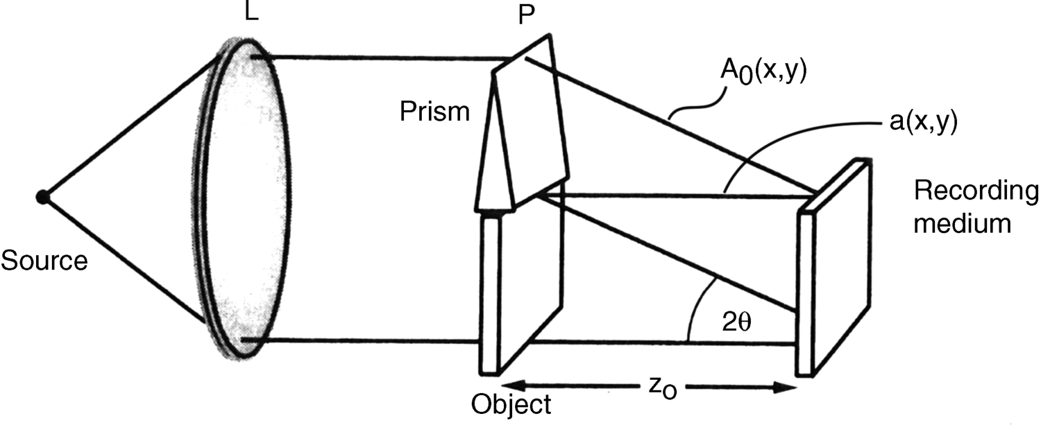
The recording in this method is depicted in Figure 6.3. The collimated light passes the object at the distance zo, assumed to be transparent, and strikes the recorder as the wave a(x, y) in Equation 6.1. The light passing the prism is refracted by an angle 2θ off the normal to the recorder. This represents the new reference wave Ao(x,y) off the normal, from which the denotation offset reference hologram for the Leith–Upatnick hologram is derived. Ao(x, y) has the form
Figure 6.3 The generation of the offset reference hologram with the reference wave Ao(x, y) and the image wave a(x, y).
The exponent in Equation 6.14 is deduced from the analytical expression for the propagation of a planar wave front as, for example, derived in Chapter 1, ref. [25], p 21. There a wave vector of magnitude k in the product kr, where r is the magnitude of the vector to the location of the wave corresponding to y, describes the propagation of the wave toward the viewer who is away from the source. With a positive sign of kr the wave travels in the opposite direction away from the viewer. The product
is the angular frequency in the y-direction associated with a wavelength λy = 1/fy. As depicted in Figure 6.4, the recorder experiences the wavelength λ in a direction parallel to its surface with
Figure 6.4 The calculation of the wavelength λ in the recorder from the wavelength λ y of Ao(x, y).
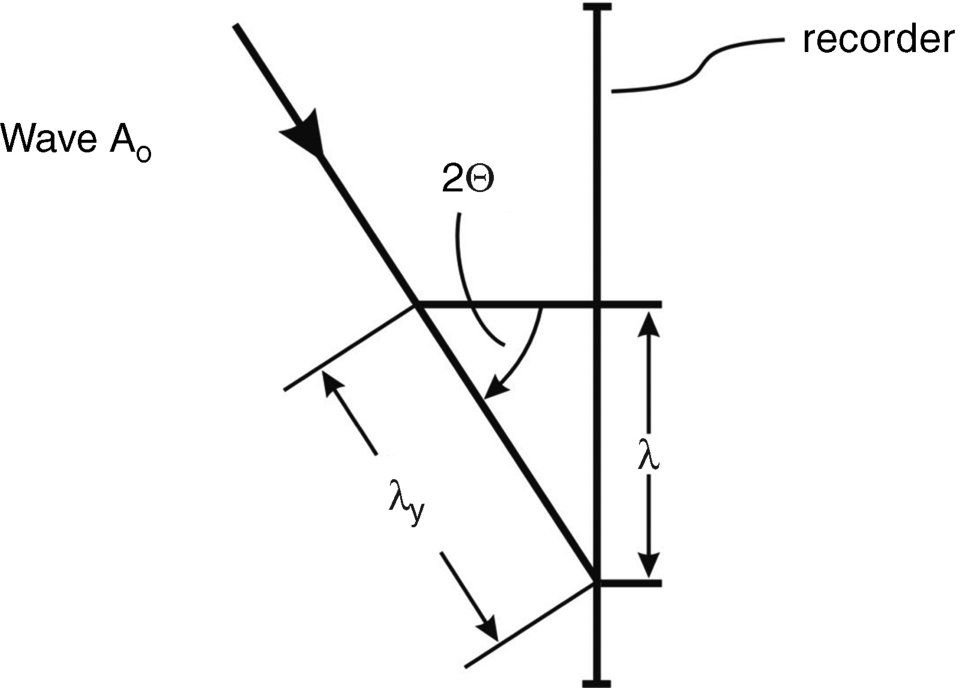
We can now introduce a wave vector of magnitude k = 2πfy = 2π sin 2θ/λ in the y or 2θ direction for the propagating wave front in Equation 6.14 away from the source of light.
We again assume ![]() . Then, introducing Ao(x, y) in Equation 6.14 instead of A(x, y) as a new reference wave into Equation 6.5 yields
. Then, introducing Ao(x, y) in Equation 6.14 instead of A(x, y) as a new reference wave into Equation 6.5 yields
or with Equation 6.4ab
If for the reconstruction the intensity pattern in Equation 6.17 is illuminated by a coherent wave B with ![]() hitting the transparent hologram vertically as shown in Figure 6.5, the reflected wave is, by Equation 6.17,
hitting the transparent hologram vertically as shown in Figure 6.5, the reflected wave is, by Equation 6.17,
Figure 6.5 Reconstruction of the offset reference hologram and the ensuing three output images.
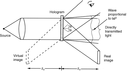
The portion ![]() is the directly transmitted light from the source in Figure 6.5. For the two other portions the recorder works as a source of light. The portion
is the directly transmitted light from the source in Figure 6.5. For the two other portions the recorder works as a source of light. The portion
directly contains the image a(x, y). Due to the positive sign in the exponent, the image travels as seen by the viewer in the direction toward the source of the light, but contrary to the wave in Equation 6.14 with the negative angle 2θ provided by fy in Equation 6.17. The image at depth zo is shown on the left side of the source in Figure 6.5 as the virtual image. The part in Equation 6.19
travels away from the source to the viewer at an angle +2θ the same way as Ao(x, y) in Equation 6.14. So its image lies on the right side of the recorder source at the distance zo as the real image. The real image belongs to the complex conjugate ![]() , while the virtual image is associated with a.
, while the virtual image is associated with a.
The most important result is that the desired images a or ![]() are optically separated from the other undesired portions of the reconstruction. This is due to the angular offset of the reference wave.
are optically separated from the other undesired portions of the reconstruction. This is due to the angular offset of the reference wave.
If the offset angle 2θ is too small the desired images a and ![]() overlap the other portions of I(x, y) and are then distorted. The minimum angle 2θ to avoid the overlap is derived in [4], pp. 310–311.
overlap the other portions of I(x, y) and are then distorted. The minimum angle 2θ to avoid the overlap is derived in [4], pp. 310–311.
Both portions a and ![]() are simultaneously available. A reading beam
are simultaneously available. A reading beam ![]() does not make sense, because, due to the positive sign in the exponent, it would propagate in the reverse direction away from the recorder.
does not make sense, because, due to the positive sign in the exponent, it would propagate in the reverse direction away from the recorder.
So far we have considered the image wave a(x, y) and the reference A(x, y) to be planar coherent waves. In the case when these waves originate from a point light source, as shown in Figure 6.6a and 6.6b, they are spherical waves. The coordinates x, y, and z are drawn in Figure 6.6a and 6.6b. The total field U(x, y) incident on the recorder in the x–y plane can be written as [4]
where A and a are the complex numbers in Equations 6.1 and 6.2 and xr, yr, zr as well as xo, yo,zo are the coordinates of the point sources of the reference and of the image in Figure 6.6a. In the exponent of Equation 6.22 a quadratic phase approximation of the spherical wave is used before the wave hits the recording medium. The intensity written into the medium is, according to Equation 6.5,
or in short
where t1 and t2 represent the last two terms in Equation 6.23.
Figure 6.6 The point sources of the object and of the reference (a) for recording and (b) for reconstruction.
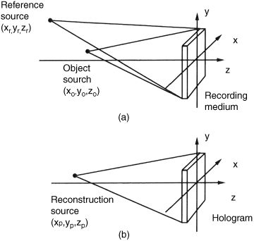
For the reconstruction, I(x, y) is illuminated, as shown in Figure 6.6b, by a spherical wave Up(x, y) originating from point xp, yp, zp represented by
where B is a constant. Reading I(x, y) implies forming Up(x, y) I(x, y), in which the image-containing portions are
and
The spherical waves U(x, y) in Equation 6.22 emerging from an object point and from a reference point have to converge to an image point xi, yi, zi after the reconstruction by the reference beam Up(x, y) with wavelength λ2 in Equation 6.24. This converging image can be described as
Ui(x, y) as well as U1(x, y) and U2(x, y) are waves heading for the same image point. Hence they must exhibit the same coefficients in the exponents. This yields
![]()
or
where the upper signs stem from U2(x, y) associated with ![]() and the lower signs from U1(x, y) associated with a. If zi is negative the image is virtual and lies to the left of the hologram; if it is positive the image is real and is to the right of the hologram.
and the lower signs from U1(x, y) associated with a. If zi is negative the image is virtual and lies to the left of the hologram; if it is positive the image is real and is to the right of the hologram.
If we equate the coefficients of the linear terms of x and y in Equations 6.27 and 6.25 as well as in Equations 6.27 and 6.26 we obtain
(6.28b)![]()
Equations 6.28a–c provide the location of the image point after reconstruction dependent on the location xo, yo, zo of the object point, on the location xr, yr, zr of the reference source, and on the location xp, yp, zp of the reconstruction source. The dependence of xi and yi on zp is explained by zi in Equation 6.28.
For the derivation of Equations 6.28a–c the reconstruction wave Up(x, y) in Equation 6.24 has the same direction of propagation as the image wave a(x, y) and the reference wave A(x, y) in Equation 6.22, which is indicated by the minus sign in the exponents. This is no longer the case if the generation of the hologram in Figure 6.7a and the pertinent reconstruction in Figure 6.7b occur with different directions of the reference wave and the reconstruction wave. As a consequence the reconstruction wave has the opposite sign in the exponent. It is an anti-reference wave with a positive sign in the exponent. So this reconstruction wave is the complex conjugate of the reference wave.
Figure 6.7 (a) Recording of the hologram. (b) The reconstruction of the hologram by a wave which is the complex conjugate of the reference wave.
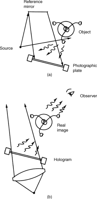
Points on the object in Figure 6.7a closest to the photographic plate, and closest to the viewer during recording, appear to the viewer during reconstruction in Figure 6.7b again closest to the photographic plate, but that is farthest away from the viewer. So for the viewer the distances are inverted, generating a peculiar image sensation. Images of this kind are called pseudoscopic, while images with the normal parallax relation are orthoscopic.
As a consequence of this inversion the viewer has for larger images the sensation of a smaller depth of focus. This depth of focus increases for smaller images.
Equations 6.28a–c describe the mapping of point xo, yo, zo on the surface of an object into the point xi, yi, zi in the 3D image after reconstruction. That way, the equations describe point by point the mapping of all points on a 3D object into the corresponding points in the same 3D image after reconstruction. Hence the equations demonstrate that a viewer can perceive a true 3D image from all its perspectives.
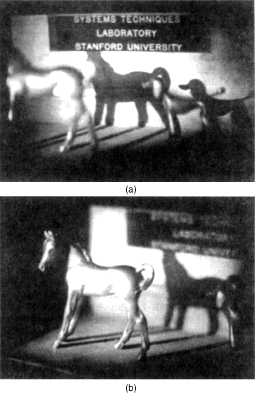
As a practical example for a true 3D image Figure 6.8a depicts a virtual image reconstructed from a hologram. The shadow of the horse appears further behind. After the camera had been moved to the right, the 3D virtual image shown in Figure 6.8b demonstrated that the camera was able to look partly behind the horse [4].
Figure 6.8 (a) Virtual image with a horse and its shadow. (b) Virtual image as in (a) but after the camera has been moved to the right.
The spherical waves originating from the object points strike each point on the recording medium. Hence each point in the intensity I(x, y) receives contributions from all object points hit by the illuminating wave. Thus each point in the image a(x, y) contains contributions from all other points.
The physical causes of all these phenomena are electromagnetic fields and waves. The field of diffracted waves is given by diffraction integrals which are investigated when optical properties only explainable by the fields are concerned. The approach with phasors in this section uses only the magnitude and phase of the waves at a location x, y, which, as has been shown, is able to derive essential properties of holography in an easier way.
The first successful extension of holography to 3D objects was reported in [7].
Some practical problems with holography are now listed [4]. The coherence length of two beams in the temporal and spatial domains is not always long enough. In the time needed for recording and reconstruction it has to be maintained to within a fraction of the wavelength, which is best achieved by using lasers. The time for the exposure of the film is shortened by applying a powerful laser. This certainly is helpful because the coherence length of a laser is also not perfect. In the spatial domain differences in the path length of the two beams also distort coherence and should be equalized. This is not easily done in large holograms with inherently different path lengths. Very stringent requirements are associated with the recording of 3D objects where emulsions with a high resolution of 2000 cycles per mm are needed. These emulsions, however, tend to be less sensitive. A further problem is the limited dynamic range of photographic recording materials, which may be alleviated by using diffused light [7]. This generates a more uniform hologram. The virtual image appears to be illuminated from the back by diffused light. A viewer looking at a reconstructed hologram through only a portion of the hologram will still perceive the entire hologram as every point contributes to every other point.
The use of photographic materials for recording holograms is of course not fit for real-time consumer 3D applications, such as for mobile devices or home TV. Other recorders, such as LCDs, require a string of electrical signals for recording which would, together with the reconstruction, be too slow for real time. They might also not offer a high enough pixel density for the larger volume of 3D information. However, LCOS or OLED might get close to becoming acceptable.
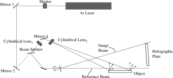
A hologram can be used as a screen for image projection. Figure 6.9 shows the recording for such a screen (hologram) with an Ar laser [8]. The beam splitter creates both the image beam reflected and diffracted from the object and the reference beam, which is diffused in order to cover the entire holographic plate. The diffusor is adjusted such that its ray in the long axes forms a straight line with the ray from the point light source. Cylindrical lenses widen the image beam to cover the width of the hologram. The path lengths of both beams from the beam splitter to their interference on the holographic plate should exhibit equal lengths. This is only approximately achievable and even less so toward the borders of a large holographic plate. The remedy is the mosaicking of the plate, as will be shown below. The coherence-enhancing adjustment of the relative positions of the diffusor, the reference beam, and the screen is essential for full color representation.
Figure 6.9 Practical generation of a hologram as a screen for projection.
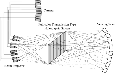
The projection of the intensity in the transmissive holographic plate in Figure 6.10 generates the viewing zones pertaining to the various projections of the cameras.
Figure 6.10 Generation of viewing zones by projectors illuminating the screen.
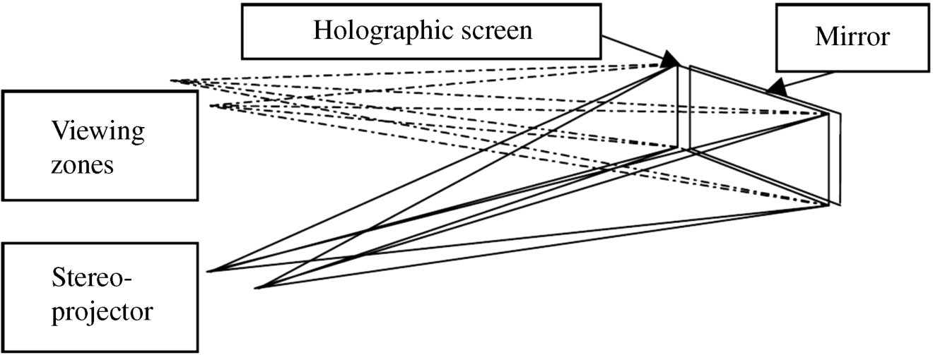
The operation of the screen in reflective mode in Figure 6.11 doubles the viewing angle. This is achieved by placing a mirror at the back of the screen.
Figure 6.11 A holographic screen working in the reflective mode.
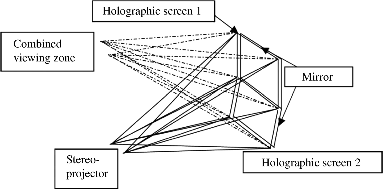
Subdivision of the reflective screen by mosaicing in Figure 6.12 generates smaller screens where the coherence between the beams is easier to maintain. There certainly is a problem with the visibility of the seam between the mosaics. In this example the hologram is called a screen because the projectors shining light on it generate the image.
Figure 6.12 A mosaiced screen creating viewing zones.
6.4 Digital Holography Based on the Fourier Transform
An object is characterized by its electromagnetic field Uo(x, y) and the hologram by its field Uh(u, v).The transition from Uo(x, y) to Uh(u, v) is determined by diffraction. This description applies for a planar wave, where the xy- or the iv-plane in which the wave propagates is perpendicular to the direction of the propagation. For the transition, physics offers several diffraction integrals suitable for specific problems. In the case of planar waves the transition is defined by the Fourier transform
The Fourier integral is the least complex but applies only to more shallow depths, while the Fresnel integral includes deeper depths and the Fraunhofer integral is the most general but also more complex.
In short we call Uo(x, y) the object and Uh(u, v) the hologram field. This field-based explanation is clearly outlined in [4]. The inverse Fourier transform
provides the object field Uo(x, y) from a given hologram field Uh(u, v). The transition with the inverse Fourier transform in Equation 6.30 can also be performed by a lens with focal length f, as depicted in Figure 6.13[9], which is of course easier and faster than being executed by the numerical calculation of the inverse Fourier transform, even if the FFT algorithm is used. This reconstruction of Uo(x, y) renders the hologram Uh(u, v) very attractive for real-time holography.
Figure 6.13 A lens performing the inverse Fourier transform of a hologram.
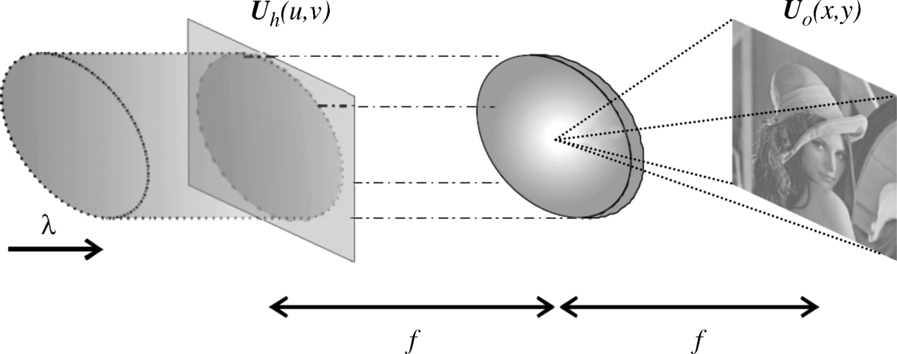
If we can generate the hologram Uh(u, v) according to Equation 6.29 as the Fourier transform of the object field Uo(x, y), then the lens in Figure 6.13 performing the inverse Fourier transform according to Equation 6.30 provides a view of the object at the speed of light. The remaining problem is to generate the hologram Uh(u, v) related to the Fourier transform of the object in Equation 6.29.
There are at least two possibilities to generate the hologram Uh(u, v). We can perform the Fourier transform with a computer, which is as a rule not a real-time process, or we can search for an approximate solution with the possibility of being faster and even as fast as a real-time procedure requires. The first approach is further pursued in this section, whereas the next section will present steps for the second approach.
For the application of a computer the data have to be sampled, that is, discretized, and then rendered binary, that is, digitally, encoded. For this we discretize in Equation 6.29 the areas in the u, v domain into pixels sized Δu − Δv and in the x, y domain sized Δx − Δy. The extensions of the images in the u, v domain are Lu − Lv and in the x, y domain Lx − Ly.
Shannon's sampling theorem [10, 11] or [4], p. 22, requires
and
As the xy-coordinates in Equation 6.29 are divided by λf, the lengths Lx and Ly also have this divisor.
To electrical engineers the sampling conditions (6.31a,b) are known from the t- and the f-domains as
where Δt is the distance between the samples corresponding to Δu and 2fc corresponding to Lx/λf which is the full width from −fc to fc of the spectrum limited by the cut-off frequency fc.
The number of pixels on the lengths Lx and Lu are
and
where we have required Nu = Nx as both domains have to exhibit the same number of matching pixels. The same equations apply for y and v.
We introduce the discretizations x = mΔx, y = nΔy, u = pΔu and v = qΔv. Then the term in the exponent of Equation 6.29 assumes the form
The first portion of Equation 6.34 becomes, with the equality sign in Equation 6.31a and Equations 6.33a, b,
In the same way we obtain for the second portion qn/Nv. The discretized form of Equation 6.29 is, with Equation 6.35,
This is the discrete Fourier transform. For a calculation on a computer Uh(pΔu, qΔv) has to be presented in a binary code. The information on Uo(x, y), the magnitude and the phase, has to be provided from the object.
Uh(pΔn, qΔv) represents complex values in each pixel p, q with
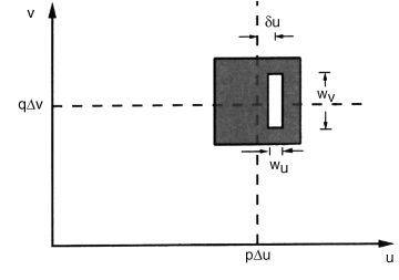
This type of hologram is realized by a photographic film with the pixel location p, q in Figure 6.14. The rectangle around the center pΔu, qΔv of the black pixel has the white transparent area ![]() . That way, if the hologram is illuminated by collimated light in Figure 6.13 perpendicular to the surface of the film, the inverse Fourier transform providing lens receives an intensity proportional to
. That way, if the hologram is illuminated by collimated light in Figure 6.13 perpendicular to the surface of the film, the inverse Fourier transform providing lens receives an intensity proportional to ![]() .
.
Figure 6.14 A single pixel in a computer-generated hologram.
As proposed in [12–14], the phase is realized by the slanted reference wave Ur(u, v) in Figure 6.15 striking the hologram at an angle 2θ from the normal of the hologram. The equation for Ur (u, v) is
Figure 6.15 The detour-phase hologram with lines of equal phase in the reference wave.
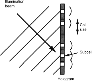
For each value of u the hologram receives a different phase angle. This is visible from the equal phase lines of Ur (u, v) in Figure 6.15. This phase angle is also transferred to the wave leaving the hologram toward the lens by shifting the center of the transparent area from the center of the pixel in Figure 6.14 to the right. The amount of shift is given by the distance in phase by which the reference wave is impinging on the points of the hologram. This can be visualized by assuming that the two equal phase lines in Figure 6.15 represent the phases from 0 to 2π. Then all the points on the hologram between these two lines receive phases varying from 0 to 2π. The shift of the center of the transparent area is to the point corresponding to ϕpq. This arrangement is called the detour-phase hologram.
The type of Fourier transform performed by the detour-phase hologram is
This is an approximation to the Fourier transform which was found to be accurate enough for Δx![]() arcsin 2θ/λ [4]. The reading out of the hologram providing the input for the lens in Figure 6.13 requires illumination of the hologram by the offset reference beam in Figure 6.15. Then the second part of this holographic generation of a 3D image, the performance of the inverse Fourier transform of the hologram by the lens, is very fast, actually at the speed of light. However, the first portion of the process, the calculation of the Fourier transform of the object by a computer, is slow and not able to be performed in real time for a still object and even less for a moving one. In cases where real-time processing is not needed, such as medical, microscopic, or other scientific applications, as well as for education and advertisements, digital holography is already a feasible process [15–17]. However, these areas are not the topic of this book. Nevertheless, the description of the process steps might be a challenge for engineers and physicists to transform them into faster implementations.
arcsin 2θ/λ [4]. The reading out of the hologram providing the input for the lens in Figure 6.13 requires illumination of the hologram by the offset reference beam in Figure 6.15. Then the second part of this holographic generation of a 3D image, the performance of the inverse Fourier transform of the hologram by the lens, is very fast, actually at the speed of light. However, the first portion of the process, the calculation of the Fourier transform of the object by a computer, is slow and not able to be performed in real time for a still object and even less for a moving one. In cases where real-time processing is not needed, such as medical, microscopic, or other scientific applications, as well as for education and advertisements, digital holography is already a feasible process [15–17]. However, these areas are not the topic of this book. Nevertheless, the description of the process steps might be a challenge for engineers and physicists to transform them into faster implementations.
For consumer applications, such as mobile devices or home TV, real-time processing is mandatory. An attempt to achieve this based on the process steps presented in this section will be presented in the next section.
6.5 A Holographic Laser Projector
The presentation on the holographic projector in Figure 6.13 [9] does not reveal the algorithm for the generation of the hologram Uh(u, v). The solution is an approximation claimed to be a real-time process. As the proposal that is able to alleviate the shortcomings of the approximation solution in terms of visibility of the reduced quality of the image is very interesting, it is presented here [18].
Instead of writing the phasor
![]()
in Equation 6.37 into the hologram, only the discretized phase values ϕp,q are used. The subjective quality of the pertinent 3D image at the output of the lens is reduced. The perceptually pleasing properties of such an image are enhanced by minimizing the variance of noise inherent in the image. It was found that including added noise and minimizing the variance of a temporal sequence of such images is even more successful. In each image of this sequence the added noise is different.
We first look at the minimization of the noise in a sequence of noisy images. The reconstructed image leaving the phase-only hologram is Uop(x, y). After the addition of noise we obtain the image ![]() . N of these images with different noise added are generated, so i = 1, 2,. . ., N. Each image has the variance σ2 of noise. The eye perceives the intensities
. N of these images with different noise added are generated, so i = 1, 2,. . ., N. Each image has the variance σ2 of noise. The eye perceives the intensities
The time-averaged sum of intensities encountered by the eye is
According to the central limit theorem, the variance of the time-averaged sum is
This means that the viewer perceiving a fast enough sequence of N images has the sensation of noise N times smaller than the noise in a single image. This also includes a reduction in the inherent noise stemming from the phase-only hologram.
A realization of the entire procedure is shown in Figures 6.16 and 6.17. In Figure 6.16 the phase-only hologram stored in a microdisplay is time sequentially illuminated by the colors R, G, and B with the wavelengths λr, λg, and λb. For this to work, the hologram has to be switched time sequentially into a hologram for red, green, and blue. The reflected holographic intensity pattern passes a demagnifying lens and a lens performing the inverse Fourier transform, which generates the color 3D images. Frame sequential color presentation is applied, so each color occupies a third of the frame time.
Figure 6.16 The reconstruction of a color 3D image from a phase-only hologram.
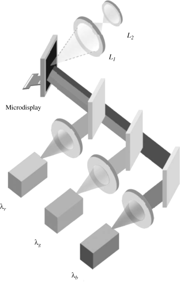
Figure 6.17 The sequence of color images with added noise used for minimization of the variance of noise.

The formation of the N subframes needed for minimization of the variance of noise takes place at the just generated 3D image as depicted in Figure 6.17. The noise is time sequentially added creating the sequence ![]() in Figure 6.17. The image for one color stays visible in space as long as the pertinent laser emits color, which is one-third of the frame time. For a 60 Hz frame this is about 5.3 ms. This is also the time available for the addition of noise and the time that the viewer perceives the image sequence in Equation 6.41. The same thing happens to the two other colors in the remaining two-thirds of the frame time.
in Figure 6.17. The image for one color stays visible in space as long as the pertinent laser emits color, which is one-third of the frame time. For a 60 Hz frame this is about 5.3 ms. This is also the time available for the addition of noise and the time that the viewer perceives the image sequence in Equation 6.41. The same thing happens to the two other colors in the remaining two-thirds of the frame time.
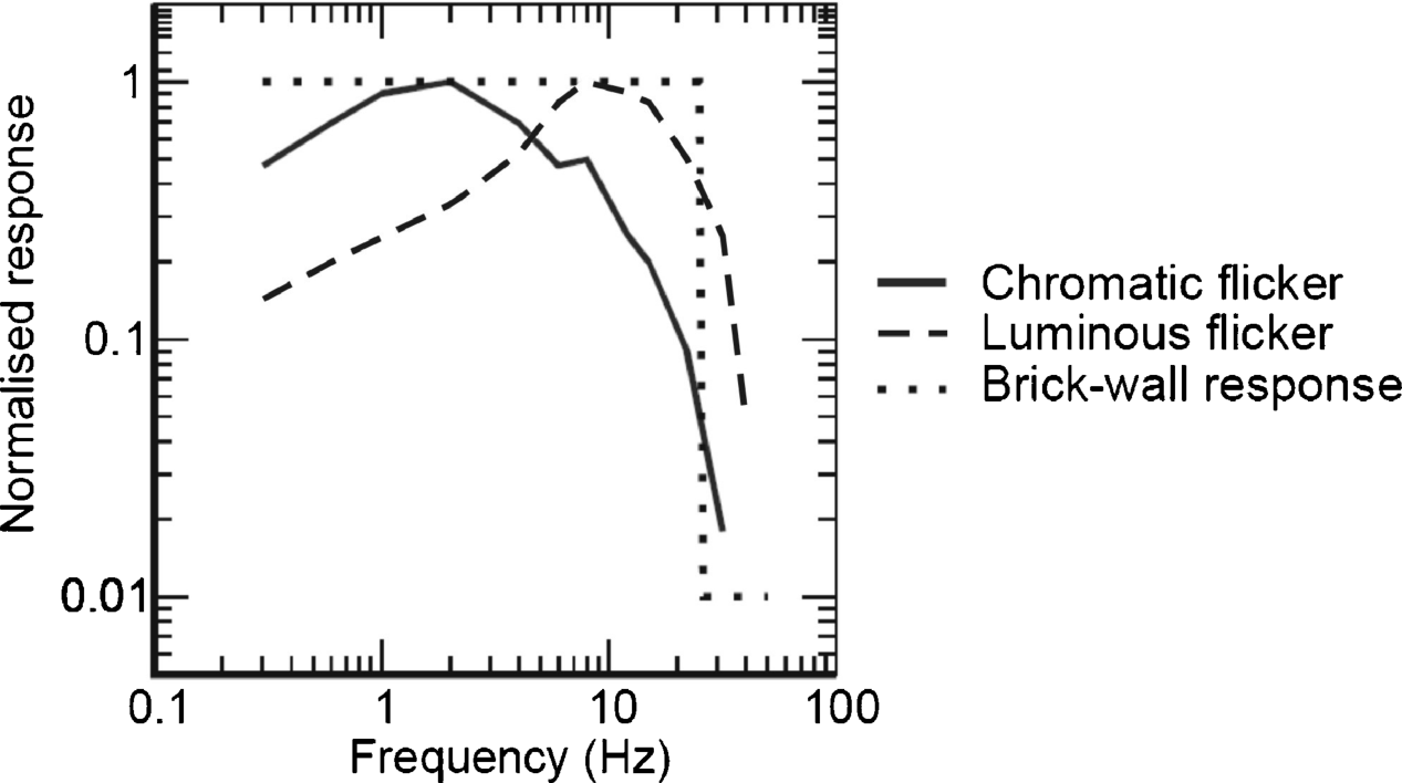
Switching to the subframes causes flicker. The response of the eye to chromatic and luminous flicker in Figure 6.18 [18, 19] is a lowpass with a cut-off frequency of 25 Hz corresponding to a time of 40 ms. This is the time within which the time averaging in Equation 6.41 takes place. The perception of the time-averaged image Vx,y can be expressed by
Figure 6.18 Perception of flicker by the human eye.
The microdisplay has to present the three color holograms within a frame time. If it is an LCOS display, faster FETs than the regular TFTs are used. In addition, the smaller cell gap than in a conventional LCD provides a larger electric field which also increases the switching speed. Due to its very short response time, an OLED display would also meet the speed specification. So displays which are fast enough are available. As the system does not require polarization, there is also a minimum loss of light. The bottleneck in speed is the generation of the Fourier transform for the hologram. If the phase-only hologram is a real-time process then the method outlined can offer real-time processing in all its parts.
This approach may serve as a model for further attempts to fast holography.
The author gratefully acknowledges permission to reproduce figures granted by the publisher and institution named below. The sources of the figures and tables are also listed below together with their corresponding numbers in this book.
Roberts & Company Publishers
| J.W. Goodman, Introduction to Fourier Optics, 3rd Edition, 2005 | |
| p. 299, figure 2.9 | reproduced as Figure 6.1 |
| p. 307, figures 9.6, 9.7 | reproduced as Figures 6.3, 6.5 |
| p. 312, figures 9.9a,c | reproduced as Figures 6.7a,b |
| p. 315, figures 9.11a,b | reproduced as Figures 6.8a,b |
| p. 317, figures 9.12a,b | reproduced as Figures 6.8a, b |
| p. 361, figures 9.40, 9.41 | reproduced as Figures 6.15, 6.14 |
Society for Information Display (SID)
| SID – Symposia and Conferences | |
| SID 00 p. 1225, figures 1, 2, 3, 4 | reproduced as Figures 6.9, 6.10, 6.11, 6.12 |
| SID 08 p.1074, figures 1, 3, 4, 5 | reproduced as Figures 6.13, 6.18, 6.16, 6.17 |
1. Gabor, D. (1948) A new microscopic principle. Nature, 161, 777.
2. Gabor, D. (1949) Microscopy by reconstructed wavefronts. Proc. R. Soc. A, 197, 454.
3. Gabor, D. (1951) Microscopy by reconstructed wavefronts II. Proc. Phys. Soc. B, 64, 449.
4. Goodman, J.W. (2005) Introduction to Fourier Optics, 3rd edn, Roberts, Greenwood Village, CO.
5. Leith, E.N. and Upatnick, J. (1962) Wavefront reconstruction and communication theory. J. Opt. Soc. Am., 52, 1123.
6. Leith, E.N. and Upatnick, J. (1963) Wavefront reconstruction with continuous-tone objects. J. Opt. Soc. Am., 53, 1377.
7. Leith, E.N. and Upatnick, J. (1964) Wavefront reconstructions with diffused illumination and three dimensional objects. J. Opt. Soc. Am., 54, 1245.
8. Son, J.-Y. et al. (2000) Holographic screen for 3-dimensional image projection. SID 00, p. 1224.
9. Buckley, E. (2008) Holographic laser-projection technology. SID 08, p. 1074.
10. Wittacker, E.T. (1915) On the foundations which are represented by expansion of the interpolation theory. Proc. R. Soc. Edinburgh, Sect. A, 35, 181.
11. Shannon, C.E. (1949) Communication in the presence of noise. Proc. IRE, 37, 10.
12. Brown, B.B. and Lohmann, A.W. (1966) Complex spatial filter. Appl. Opt., 5, 467.
13. Brown, B.B. and Lohmann, A.W. (1969) Computer generated binary holograms. IBM J. Res. Dev., 13, 160.
14. Lohmann, A.W. and Paris, D.P. (1967) Binary Fraunhofer holograms generated by computer. Appl. Opt., 6, 1739.
15. Naughton, T.J. et al. (2002) Compression of digital holograms for three-dimensional object reconstruction by use of digital holography. Appl. Opt., 41, 4124.
16. McElhimey, C.P. et al. (2008) Extended focused imaging for digital holograms of macroscopic three-dimensional objects. Appl. Opt., 47, D71.
17. Javidi, B. et al. (eds.) (2009) Three-Dimensional Imaging, Visualization and Display, Springer, Berlin.
18. Cable, A.J. et al. (2004) Real-time binary hologram generation for high quality video projection applications. SID 04, p. 1431.
19. Kelly, D.H. and Norren, D. (1977) Two band model of heterochromatic flicker. J. Opt. Soc. Am., 67 (8), 1081.


