Chapter 7
Volumetric 3D Displays
7.1 The Nature of Volumetric Displays
Stereoscopic and autostereoscopic displays use two images, one for the left and one for the right eye, to create a 3D effect. Volumetric displays, as a rule, provide one image for both eyes while the 3D effect is created by a stack of images in the form of planar displays on top of each other, each at a different depth or distance from the eyes. These distances will be essential for generating the sensation of depth. Referring to the volume of these multi-depth displays, they are called a volumetric display. When the stack of displays is stationary, it is referred to as a static volume display. The perception of volume, that is, the third dimension, can also be stimulated by mechanical displays, where a rotational or translatory movement sweeps through the volume while emitting images at various depths. This volumetric mechanical arrangement is called a swept volume display [1].
The next section will be devoted to static volume displays, which is followed by a section on swept volume displays.
In all volumetric displays the eyes focus on images at different depths, in that way creating a 3D perception which avoids the mismatch between accommodation (focus) and vergence (rotation) of the eyeballs. The mismatch was treated in Chapter 1 and especially in Figure 1.1. If the eyes focus on P in Figure 1.1, then the axes of the eyes rotate (the vergence) by the disparity angles γ out of the fovea. The focus on P (distance, depth) and the disparity angles γ (vergence) match. This is no longer the case for stereoscopic and autostereoscopic imaging which have only one depth, that is, the distance between the eyes and the screen of the displays, even though the two images for the eyes convey the sensation of different depths. This discrepancy between the focus on the distance to the screen and the vergence stimulated by the two images does not occur in integral imaging, holographic, and volumetric displays.
In the stack of images of a volumetric display the pixels in each plane have three coordinates: x and y in the image plane and z for the depth location of the display. The pixels are volume pixels or, in short, voxels. The problem is to access them for addressing or enabling them and for the emission of light.
In the next section we investigate methods for accessing the voxels in static volumes. For two planes at different depths from the eyes we have already done this in Section 3.5, where a major problem was fusion of the views from the two depths. In order to enhance this fusion of depths, again two images for the eyes and polarization to discriminate between the two images were applied. This takes the solution into the category of autostereoscopic displays and its treatment in the pertinent Section 3.5. The number of displays in a volume treated in the next section is always larger than two, which justifies the treatment of them in the sections on volumetric displays, even though, as we shall see, for three planar images in a volume one is tempted to enhance the reality of 3D by again having recourse to two images for the eyes, as we encountered for the volumetric displays in Section 3.5.
7.2 Accessing and Activating Voxels in Static Volumetric Displays
The problem is how to address a voxel or a group of voxels at a selected depth of the volume and how to enable those voxels to contribute to the display of an image originating from the selected depth.
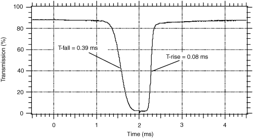
In the first approach to this problem [2] the stacked displays consist of polymer-stabilized cholesteric texture (PSCT) displays which are transparent if no voltage is applied across the voxels. If a voltage is applied they turn opaque and reflect an image projected onto them, thus forming a scattering shutter. The arrangement in Figure 7.1 consists of PSCT displays called a multiplanar optical element (MOE), its voxel driver, and a high-speed projector. As soon as a voltage is applied to a group of voxels at a selected depth the projector can throw an image pertaining to that depth onto the addressed voxels, as all other voxels are transparent. The viewer perceives the reflected and scattered images by focusing on the selected depth. This process continues in a fast enough sequence comprising all the depth images. The MOE under consideration was called a depth cube and consists of 20 PSCT displays at different depths with 1024 × 748 voxels each. Figure 7.2 depicts the transmission of a voxel versus time, when the voxel is not addressed and while being addressed. In the non-addressed transparent stage the transmission is about 90%. The transition time to the opaque state is about 0.4 ms, whereas the return to the transparent state with 0.08 ms is even faster. This shutter is altogether fast; employing a ferroelectric liquid crystal display (FLCD) would be even faster but it is unable to reflect all the gray shades. Based on Figure 7.2, the time for presenting an image is 2.5 ms, resulting in 20 layers of images in a time of 50 ms, corresponding to 20 Hz for presenting one set of all 20 images. The projector has to be fast enough to present single images with a frequency of 400 Hz. The overlapping decay and rise times of the shutter transmission may be visible in the images. The rate of voxel information flowing into the projector is 20 × 1024 × 748 voxels in 50 ms, resulting in 40 million voxels per second. This indicates the high rate of information flow in volumetric displays stemming from the large number of images at different depths. If each voxel receives 10 bits of information we end up with 400 Mb/s.
Figure 7.1 Schematic of a volumetric image projector.
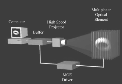
Figure 7.2 Transmission versus time of a PSCT shutter.
Without special processing the images may look like a separated sequence of 2D images rather than a single continuous 3D image. To prevent this from happening a so-called multiplanar anti-aliasing is applied. If any image is provided at a depth of 5.25, then 75% of the RGB luminance is assigned to the image at depth 5 and 25% into the same voxel at depth 6. This provides a smoothing effect, tying together the previously separated images. It may also cover up possible effects from overlapping transmissions stemming from different depths.
This volumetric 3D display is marketed with a color depth of 15 bits and a frame rate of 60 Hz. It demonstrates that a large number of planar displays are necessary for an acceptable 3D reality, resulting in a heavy load of information to be handled in real time. So sacrifices in resolution leading to a smaller density of voxels may be inevitable for now.
In [3, 4] the images at different depths are generated by a scanned array of fibers. Each fiber provides a point source of light and each fiber is individually addressed. This avoids problems with an overlong switching time. Each point source represents a voxel. The horizontal sequence of these voxels is scanned by a mirror which guides the emitted light of each voxel as an image directly to the eyes of the viewers. A slight rotation of the mirror is the only moving part of the system.
The individual addressing of each fiber allows each fiber to be set at a fixed focal distance. If the light emerging from a fiber is parallel collimated light, the eyes interpret this as light originating at infinity. In Figure 1.1 this light has indeed parallel beams for the two eyes associated with a zero disparity, which stands for an object infinitely far away. If the emerging beam is diverging, then Figure 1.1 indicates that the beams originate from a point closer to the viewer. Diverging beams with different divergent angles at the end of fibers are shown in Figure 7.3. The diverging beams correspond to larger disparities on the retina. The larger the divergence or the disparity, the closer the object. The eyes focus on the objects according to the disparity and hence according to the distance. That way, the eyes detect from which distance the beam originates.
Figure 7.3 Multiple fibers with different degrees of divergence of the exiting beams.
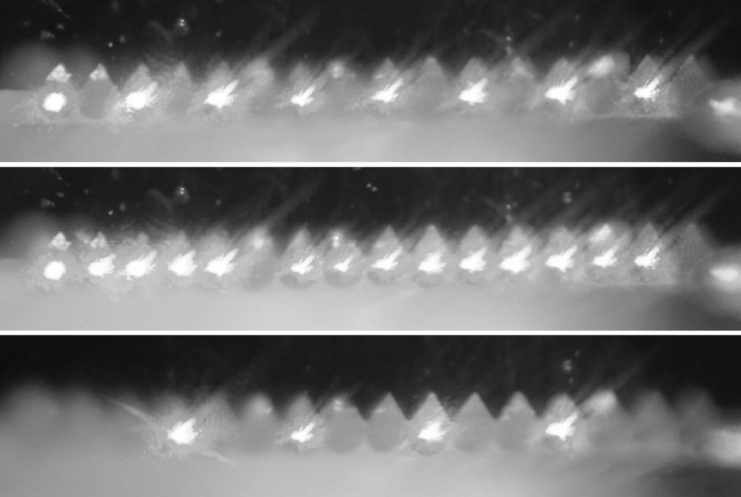
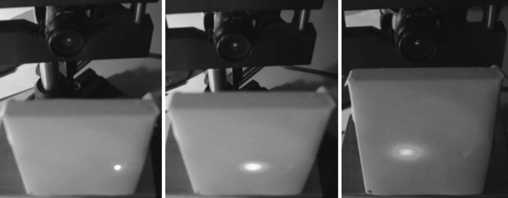
The beams in the fiber array are 125 μm apart. In order to achieve a partial superimposition of the multiple beams creating a coherent image, the light-emitting ends of the fibers are beveled. This is shown in the upper portion of Figure 7.4. The ends are cut and polished at an angle of 42° from the horizontal line of fibers. This angle was found to create total superimposition. The beveled ends work like a prism and refract the beam by 20° into a direction parallel to the surface of the cut, as shown in the lower portion of Figure 7.4. Polishing the cut at an angle of 38̊ to 40̊ leads to the appearance in Figure 7.5 and increases the superimposition while suppressing total internal reflection. Figure 7.6 shows on the left a roughly collimated beam produced by the fibers assigned to the far distance, in the middle a partially diverging beam for the center of the depth range, and on the right a highly diverging beam produced by the fibers assigned to the smallest distance.
Figure 7.4 The beveled ends of the fibers in the upper portion of the figure and the refraction of the emitted light roughtly parallel to the surface of the cut in the lower portion.
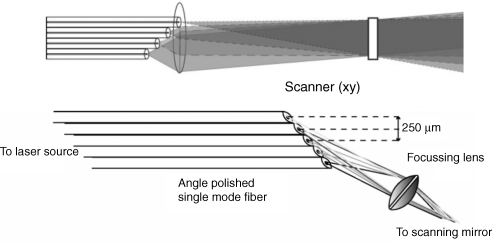
Figure 7.5 The appearance of the cut before (left), half way through (middle), and at the end (right) of polishing.
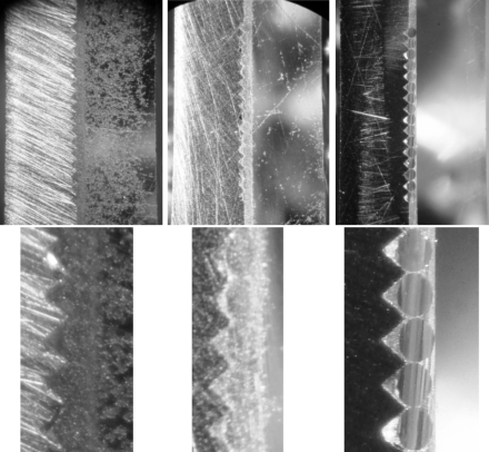
Figure 7.6 The degree of divergence of the light emitted by fibers assigned to the far distance (left), the center distance (middle), and the near distance (right) of objects.
For images with an acceptable resolution also in the depth direction, a very large number of fibers is required.
The third approach attempts to reduce the required number of planar displays by using images only at three depths, as depicted in Figure 7.7 [5]. In order to enhance the diminished depth perception, two images, one for the left eye and one for the right eye, are brought into play. The latter feature combines the volumetric display with the autostereoscopic approach, sacrificing the free selection of the viewing position which volumetric displays have so far allowed.
Figure 7.7 A volumetric display with only three planar images.
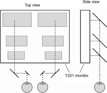
The three images seen in the top view of Figure 7.7 are read out sideward, as depicted in the side view, by mirrors, the two nearest to the viewer functioning also as beam splitters. These mirrors are needed separately for the images for the left and the right eye, which are not shown in the figure. In a periscope-like arrangement the three overlaid images are transferred into two images in an adjustable binocular distance b in front of the eyes.
The side view in Figure 7.7 depicts the distances of the three image planes from the viewer which are chosen to be separated by equal amounts measured in diopters. The reason for this choice becomes clear by considering Equation 1.1 for the depth of focus T measured in diopters and Equation 1.2 for the depth of field F measured in meters. These depths are shown in Figure 1.2. The depth of focus T between the near and the distant blurring points should be kept constant for all distances to the focus point C in Figure 1.2, thus maintaining an equal image quality around all focus points C, that is, for all distances. This entails the following consequences. If C moves closer to the viewer while T remains constant, the depth of field F in meters shrinks according to Equation 1.2, meaning that the distances to the focus point C also shrink. This is visible in the side view of Figure 7.7, where the distance between the mirrors, the focal points C of the eyes, become smaller closer to the viewer. A very desirable consequence of depth F is a sequence without or always with the same overlap. Without overlap is preferable, because the three displays in Figure 7.7 then cover their range of depths in a perceptually optimum way. For increasing depths a less than linearly increasing number of image planes are required if T in diopters is kept constant. This is an important fact for reducing the number of very costly image planes.
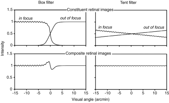
A further problem arises if an object point between two planar images has to be assigned to one of the close images as shown in Figure 7.9 by the slanted line for these object points. If the assignment is like a box filter on the left in Figure 7.9, the intensity on the retina in Figure 7.9 on the left shows a ripple stemming from the discontinuity of assignment introduced when the object lies exactly in the middle between the two neighboring planar image planes. The ripple disappears if the assignment is governed by a tent filter on the right in Figure 7.9. The rule is a gradual and not an abrupt assignment as in the box filter. This gradual assignment consists of a partition of the intensity according to the dioptric distance to the two planar images. Then the ripple on the retina in Figure 7.9 disappears.
Figure 7.8 Two assignments of intensity of an object lying in between two planar images.
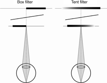
Figure 7.9 Intensity on the retina for the two assignments of intensity in Figure 7.8.
The second solution in [5] for a volumetric system with only three displays at different depths is shown schematically in Figure 7.10. Again, as in the first approach, the two eyes will be stimulated separately. Figure 7.10 shows only the arrangement for one eye.
Figure 7.10 Schematic for a volumetric display with time sequential different lenses for each of the three depths.
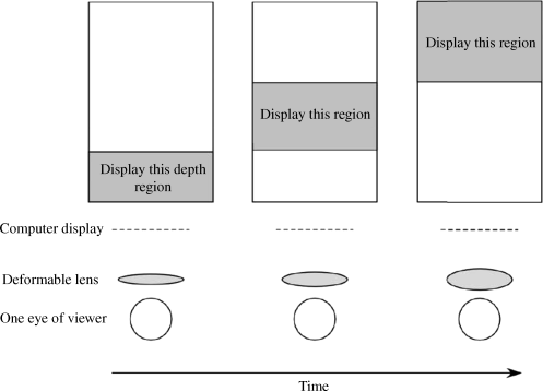
There is one fast switching lens which focuses time sequentially, for example, on the middle distance of the images from the viewer. In each stage of focus of the eyes the remaining images appear blurred according to their different distances. Each of the three stages of focus is presented with a 60 Hz frequency, so the lens has to switch at 180 Hz. This time multiplex operation replaces the three mirrors in Figure 7.7 which were required for the outcoupling of the images.
Common to both approaches in Figures 7.7 and 7.10 is the advantage of requiring only three planar images. The penalty is having recourse to two images for the two eyes, which requires fixed viewing positions.
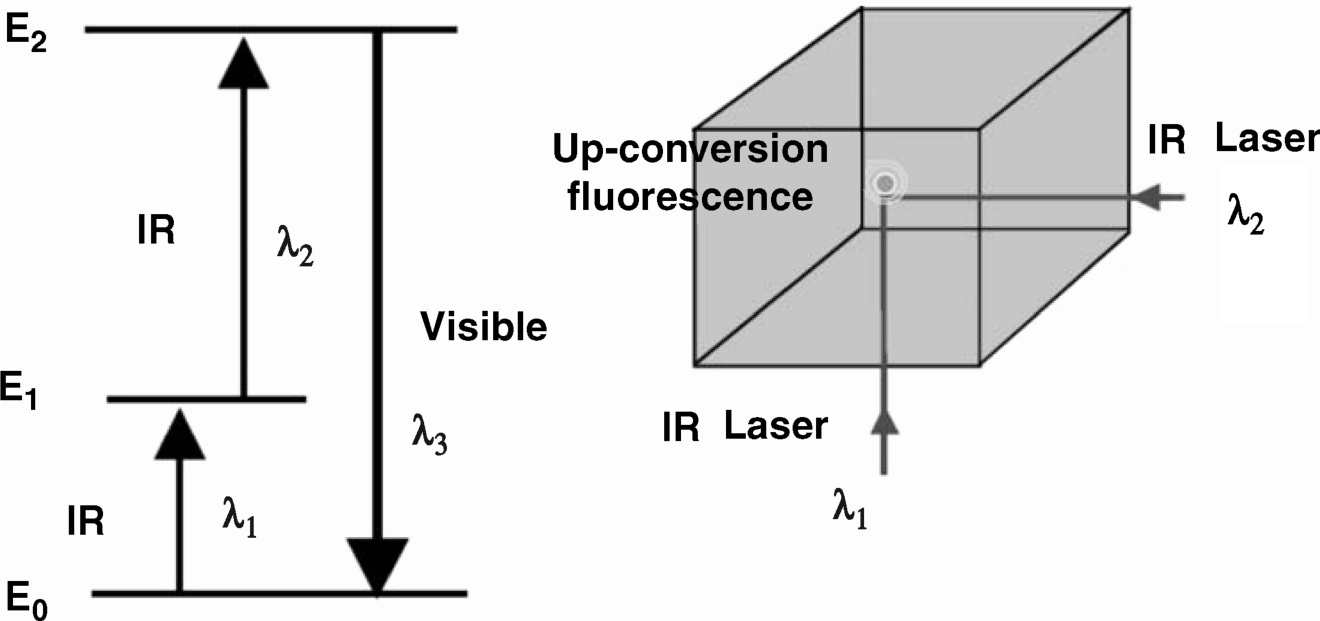
Finally we familiarize ourselves with a static volume display in which the voxels from the outside can be activated to emit light [6]. The voxels lying at the intersection of two invisible infrared laser beams are excited to emit visible light, as depicted in Figure 7.11. The first beam with wavelength λ1 lifts electrons by photon absorption from the ground energy state E0 to an intermediate level E1, while the second beam with wavelength λ2 lifts them further to the level E2 where visible light is emitted. This is an effect of fluorescence. The mechanism is called two-step–two-frequency up-conversion (TSTF-UC). The technique was introduced for displays in [7] with rare earth-doped heavy-metal fluoride glasses as voxels. For display applications the volumetric medium must be transparent to visible light and to the wavelengths used for up-conversion. Further, it has to be free of scattering and stress and must be capable of two-photon absorption (TPA). In [7] dye-doped polymers or rare earth-doped fluoride crystals were identified as usable for displays. The rare earth-doped fluoride crystals contained 1% Ho: YLF, 1% Er: YLF, and 2% Er: KY3F10. The most luminous emission was achieved with Er: KY3F10 using pumped lasers with wavelengths of 1491.1 nm and 800.4 nm.
Figure 7.11 The two laser beams for up-conversion of a voxel and the pertinent energy levels.
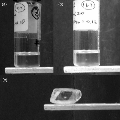
For scalable displays, crystals are not applicable. Therefore a powder of the material was ground and dispersed in an index-matched passive host forming an optical gel. A photo of the light emitted from such a gel is depicted in Figure 7.12 with various wt % of 2% Er: KY3F10. This up-conversion allows for a fast activation of the voxel. The creation of an image with this technique should be one of the next steps of further development.
Figure 7.12 The light emitted from an optical gel containing 2% Er: K3F10 powder: (a) with 10 wt % and (b) with 16 wt % doping; (c) emission from a single crystal instead of a powder.
7.3 Swept Volume or Mechanical 3D Displays
Even though it is not likely that mechanical 3D displays will make it into living rooms, the basic approaches of such displays will be briefly presented. The reason is that designers of 3D displays may be intrigued to find solutions which can be translated into electronic implementation. The common feature of mechanical 3D systems is the swept volume in which rotational or translatory movements sweep through the volume, while at each position representing a depth the pertaining image is emitted. Thus a true 3D image is perceived and the viewer can even walk around the display while experiencing different views of the object. In doing so, there is no conflict between the accommodation and the vergence, which avoids discomfort.
Mounted on the turntable in Figure 7.13 are two arrays of 16 LEDs each which emit pulsed images pertaining to the various depths reached by rotation of the table [8]. Figure 7.13 represents the vertical projection of the LEDs onto the rotating table shown in Figure 7.14, while the column of LEDs on the left side in Figure 7.13 depicts the position of the LEDs perpendicularly upward from the turntable on the drum indicated as the “display part” in Figure 7.14. The pulley box in that figure contains the motor and the control panel, the electronics providing the image content. The speed of rotation is R = 480 rpm. On the left in Figure 7.13 the vertical extent of the array of LEDs and their spacing of 5 mm are visible. The spacing in the depth direction is 7 mm in Figure 7.13, while the spacing in the horizontal direction is 1.5 mm. These spacings are identical to the pitches of the pixels. The frame frequency is f = 2R/60 s = 16 Hz, where the factor of two relates to the two images per turn provided by the two arcs. The extent of the horizontal and vertical viewing cone is 140̊ for each direction.
Figure 7.13 Arrangement of LEDs on the turntable of a mechanical 3D display.
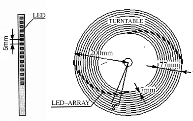
Figure 7.14 The configuration of a turntable 3D system.
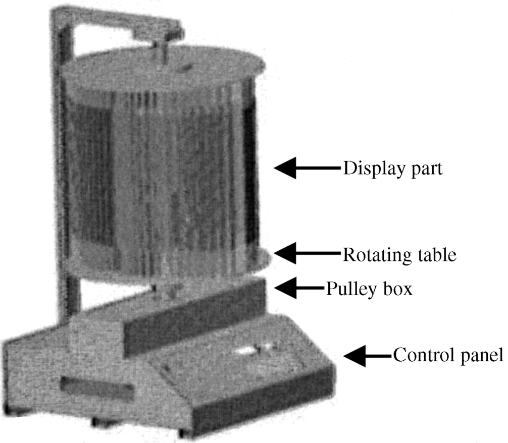
The fast switching of LEDs is required as they have to produce a short flash of light when they rotate through the position that the image belongs to. The indication of this position is provided by a rotary encoder.
There are more pixels in an image than LEDs, because each single LED is moved to various image locations.
All turntable systems have the problem that the pixel pitch is not constant, since it depends on the rotary angle of the turntable. The pitch is obtained by a projection of the location of the LEDs onto a horizontal line; it is largest when the arc of LEDs is close to parallel to the horizontal and smallest when rotated by 90° out of this position. A computer program can correct these pitch differences. The correction is more effective for a large number of pixels in the horizontal direction.
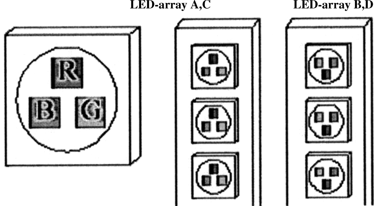
A higher pixel density and color pixels are achieved with the arrangement of LEDs shown in Figure 7.15 [9]. Instead of two arcs of LEDs, there are four of them, realized as Archimedean spirals and denominated A, B, C, and D. The two vertical columns of LED arcs A and C and B and D are arranged according to Figure 7.16 such that column group B and D is shifted downward by 4 mm from the position of group A and C. Thus the horizontal lines of the LEDs are doubled; during rotation the lines alternate between the two arcs A/C and B/D. The three colors are positioned, as shown in Figure 7.17, differently for the two groups in order to improve the color balance. The improvement is brought about by the fact that each pair of lines exhibits three colors.
Figure 7.15 The four groups of LEDs for a 3D color display.
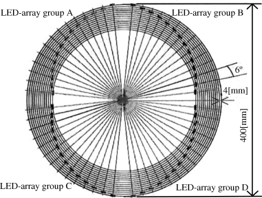
Figure 7.16 Two groups of LEDs shifted toward one another.
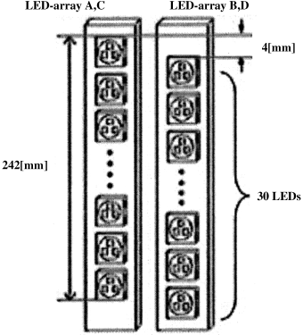
Figure 7.17 Different placements of the three color subpixels in the groups A/D and B/C.
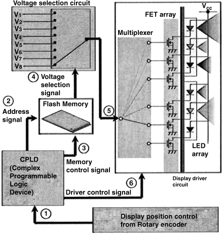
The addressing of the LED pixels, as shown in Figure 7.18, is based on writing the image content to be displayed into a flash memory, from where it is downloaded line-wise to the display voltage selection unit, which provides the voltage for the desired luminance of the individual pixels. A multiplexer distributes the voltage to an array of FETs which, by being rendered conductive, place the appropriate voltage across the color LEDs. The motor with a rotary encoder delivers a display position signal controlling the voltages across the LEDs, thus guaranteeing that the correct image signal is active at the pertinent rotary position of the LEDs.
Figure 7.18 The control circuit for a turnable 3D color display.
This turntable approach was further developed in [10] to obtain a color display with 120 pixels in the vertical, 1500 pixels in the horizontal, and 9 pixels in the depth direction resulting in 512 colors and a viewing range of 360°. The large pixel count in the horizontal direction helped to correct the large changes of the pixel pitches in this direction.
A very intriguing possibility for mechanically realizing a variable depth consists of a tensioned sheet, for example, made out of Mylar covered with a reflective layer of Al, in which the ripple in Figure 7.19 [11] is traveling from one edge parallel down to the opposite edge. A laser beam is shone parallel to the surface of the sheet to the ripple and is reflected at the slope of the ripple. The viewer perceives a point of light at the intersection of the laser beam and ripple moving through different positions of depth.
Figure 7.19 A tensioned sheet with a moving ripple for deflection of a laser beam.
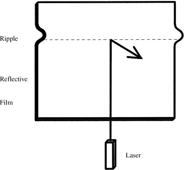
The ripple can be created by abruptly lifting and releasing the upper edge of the sheet. Pixels in the horizontal direction are generated by rotating the laser beam in Figure 7.19 in the horizontal direction or by placing an array of stationary lasers along the horizontal. Control of the intensity of the laser and its synchronization with the movement of the ripple is required to obtain a 3D image, in this approach, incidentally, without TFTs.
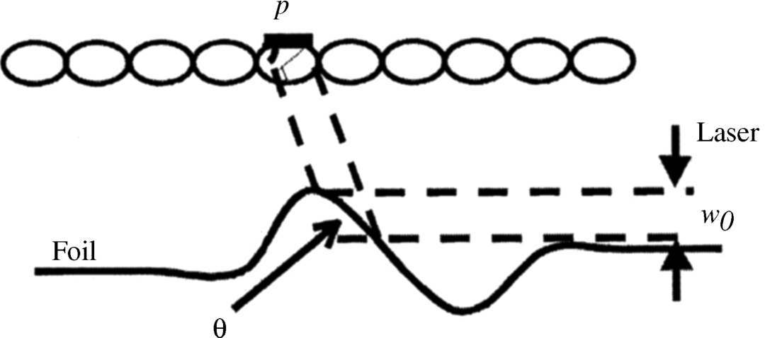
Figure 7.20 depicts how the slope angle Θ of the ripple and the width w0 of the laser beam affect the width p of the pixel. A formula for Θ dependent on geometrical parameters is given in [11]. The speed c of the ripple is derived as
(7.1)![]()
where T is the tension of the sheet and μ the density per area of the sheet; c is derived from a linear second-order partial differential equation for the location of the ripple. With this, all design parameters are available. A first experiment with a sheet 150 mm long revealed the basic functioning of the device, but further work is required.
Figure 7.20 Generation of a pixel of width p by reflection of the laser beam at the ripple.
A third solution uses the deformable membrane mirror (DMM) shown in Figure 7.21 [12]. A voltage at the membrane deforms it such that a reflected image appears focused at different distances. If no voltage is applied, the membrane is planar and the focus is at infinity; the larger the voltage, the more deformed the membrane, and hence the smaller the distance to the focus. Rather large voltages of several hundred volts are needed for the deformation.
Figure 7.21 The voltage-operated deformable membrane mirror (DMM).
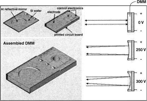
The basic idea for the operation of the device is to focus the image at such a distance which matches the vergence induced by the image in the eyes of the viewer. That way, the conflict between accommodation (focus) and vergence (disparity) is resolved.
The operation of this 3D display according to Figure 7.22a and 7.22b starts with two images (a) and (b) of an object: one with a focus at a large distance provides the background of the image, and one with a near distance focus delivers the foreground. These two images are emitted in a fast-time sequential sequence to the eyes, where in Figure 7.22a and 7.22b only one eye is drawn. The eyes can focus on the foreground and on the background with the vergence induced by the images. So true 3D is perceived during the projection of the images directly onto the retina of the eyes. It must be noted that only one viewer at a time has access to the 3D image.
Figure 7.22 The scanning laser beam and the refocused images directly presented to the retina (a) for the background and (b) for the foreground.
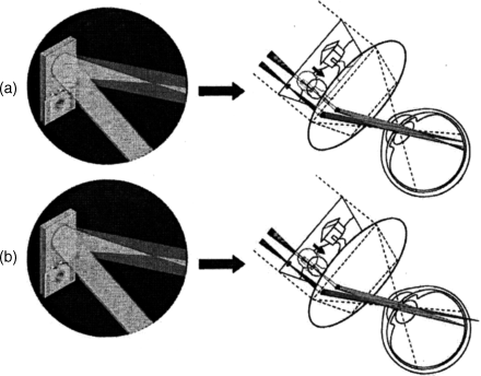
One problem is the slow change of focus at the DMM. A remedy could be to provide several channels in parallel, each with a different focus. This approach is worth pursuing further.
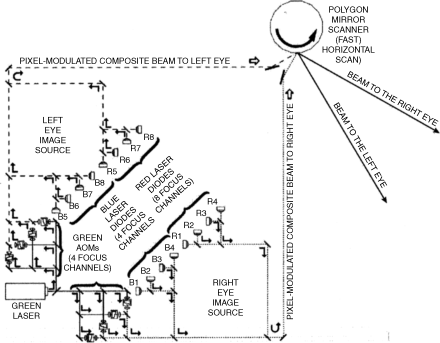
In [12] the system in Figure 7.23 realizing the DMM approach is proposed. It applies two images, one for the left and one for the right eye. So we are again confronted with two images for the enhancement of 3D reality. Two streams of multi-focus images are directed to the mirrors of a rotating polygon. The rotation performs a fast horizontal scan. The reflections from the polygon are guided by lenses toward the right and the left eye. The beams hit a galvanometer with a mirror performing a vertical scan. The result is guided by mirrors and lenses finally to the eyes, where a true 3D image is perceived.
Figure 7.23 A true 3D system with multi-focused image beams as input. (AOM=Acousto-Optic Modulator)
An application for mechanical 3D displays is in advertising and education.
The author gratefully acknowledges permission to reproduce figures granted by the institution named below. The sources of the figures and tables are also listed below together with their corresponding numbers in this book.
Society for Information Display (SID)
SID – Symposia and Conferences
| SID 03 p. 1531, figures 7.1, 7.4 | reproduced as 7.1, 7.2 |
| SID 10 p. 653, figures 3, 6, 10, 12 | reproduced as Figures 7.3, 7.4, 7.5, 7.6 |
| SID 06 p. 77, figures 1, 2, 3, 4 | reproduced as Figures 7.7, 7.8, 7.9, 7.10 |
| SID 07 p. 1228, figures 2, 10 | reproduced as 7.11, 7.12 |
| SID 03 p. 1522, figure 2 | reproduced as Figure 7.13 |
| SID 05 p. 91, figures 2, 3, 4, 5, 6 | reproduced as Figures 7.15, 7.16, 7.17, 7.14, 7.18 |
| SID 99 p. 1008, figures 1, 2, 3 | reproduced as Figures 7.19, 7.20, 7.21 |
| SID 05 p. 86, figures 2, 3, 6 | reproduced as 7.22, 7.23, 7.24 |
1. Blundell, B.J. and Schwarz, A.G. (2002) The classification of volumetric display systems: characterization and productability of the image space. IEEE Trans. Vis. Comput. Graphics, 8 (1), 66.
2. Sullivan, A. (2003) A solid-state multi-planar volumetric display. SID 03, p. 1531.
3. Schowengerdt, B.T. et al. (2010) Volumetric display, using scanned filter array. SID 10, p. 653.
4. Schowengerdt, B.T. and Seibel, E.J. (2006) True 3D scanned voxel display using single or multiple light sources. J. SID, 14/2, 135.
5. Banks, S.M. (2006) Achieving near correct focus cues in a 3D display using multiple image planes. SID 06, p. 77.
6. Downing, E. et al. (1996) A three color solid-state, three-dimensional display. Science, 273, 1185.
7. Cho, J,-H. et al. (2007) Development of a scalable volumetric three-dimensional up-conversion display medium. SID 07, p. 1228.
8. Sakamato, Y. et al. (2003) A wide-field-of-view 3D display. SID 03, p. 1522.
9. Sakamato, Y. et al. (2005) A turn-type color 3D display system using LEDs. SID 05, p. 90.
10. Akinori, I. et al. (2007) Turn-type color 3D display system using scanned arrays of LEDs. SID 07, p. 418.
11. Marston, N.S. et al. (1999) Illuminating a scanning ripple for flat-panel 3D. SID 99, p. 1008.
12. Schowengerdt, B.T. and Seibel, E.J. (2005) True 3D display technology. SID 05, p. 86.
