Chapter 8: Image-Based Techniques
In this chapter, we will show how to create a framework for a number of techniques to implement image-based effects via Open Graphics Library (OpenGL) and Vulkan and integrate them with the rest of our scene-rendering code. Most of these techniques are actually part of the postprocessing pipeline, such as ambient occlusion, High Dynamic Range (HDR) tone mapping and light adaptation, and temporal antialiasing. The idea is to render a scene and then apply an effect to it, hence the name. Besides that, shadow mapping uses somewhat similar machinery of offscreen framebuffers underneath. We will implement a very basic shadow mapping algorithm here as the first example and then return to the topic of shadow mapping, with more advanced techniques, in the next chapter.
This chapter covers the postprocessing pipeline and has the following recipes:
- Implementing offscreen rendering in OpenGL
- Implementing fullscreen quad rendering
- Implementing shadow maps in OpenGL
- Implementing SSAO in OpenGL
- Implementing HDR rendering and tone mapping
- Implementing HDR light adaptation
- Writing postprocessing effects in Vulkan
- Implementing SSAO in Vulkan
- Implementing HDR rendering in Vulkan
Technical requirements
To run the recipes from this chapter, you will need a computer with a video card supporting OpenGL 4.6 with ARB_bindless_texture and Vulkan 1.2. Read Chapter 1, Establishing a Build Environment, if you want to learn how to build demonstration applications from this book.
This chapter relies on the geometry-loading code explained in the previous chapter, Chapter 7, Graphics Rendering Pipeline, so make sure you read it before proceeding any further and run the Chapter7/SceneConverter tool before running the demos from this chapter.
All Vulkan demos from this chapter require multiple rendering passes and are using multiple input and output (I/O) textures and framebuffers. To specify these memory dependencies without using Vulkan subpasses, we insert pipeline barriers in between the rendering commands. Inserting barriers into a command buffer is performed in the shared/vkFramework/Barriers.h file, which declared a number of helper classes that essentially just emit the appropriate vkCmdPipelineBarrier() function. These helper classes are used in the form of Renderer from the previous chapters. We declare a variable, initialize that barrier with an appropriate texture handle and flags, and add this variable to the list of renderers. Make sure you read Barriers.h before proceeding with this chapter.
Implementing offscreen rendering in OpenGL
Before we can proceed with generic postprocessing effects, let's implement some basic OpenGL machinery for offscreen rendering using framebuffer objects. We will rely on this code throughout the remaining chapters of this book to implement various rendering and postprocessing techniques.
Getting ready
The code for this recipe is located in the shared/glFramework/GLFramebuffer.h. file. It would be helpful to quickly go through the entire code before reading the rest of this recipe.
How to do it…
Let's implement a simple GLFramebuffer class to handle all the underlying OpenGL framebuffer objects' manipulations and attachments:
- Our framebuffer implementation holds the width and height dimensions of the framebuffer, its OpenGL handle, and two GLTexture objects, for color and depth buffers respectively. As we do not need to render into multiple render targets, having just one of each buffer is sufficient for now:
class GLFramebuffer {
private:
int width_, height_;
GLuint handle_ = 0;
std::unique_ptr<GLTexture> texColor_;
std::unique_ptr<GLTexture> texDepth_;
- The constructor takes dimensions of the framebuffer and texture formats for color and depth buffers. Whenever a texture format is set to 0, no corresponding buffer is created. This is handy when we need color-only framebuffers for fullscreen rendering or depth-only framebuffers for shadow map rendering. Texture wrapping is set to GL_CLAMP_TO_EDGE for proper filtering of fullscreen data. Once we have attached all the textures, we should check if our framebuffer is complete. After that, it can be used for rendering:
public:
GLFramebuffer(
int width, int height,
GLenum formatColor, GLenum formatDepth)
: width_(width), height_(height) {
glCreateFramebuffers(1, &handle_);
if (formatColor) {
texColor_ = std::make_unique<GLTexture>( GL_TEXTURE_2D, width, height, formatColor);
glTextureParameteri(texColor_->getHandle(), GL_TEXTURE_WRAP_S, GL_CLAMP_TO_EDGE);
glTextureParameteri(texColor_->getHandle(), GL_TEXTURE_WRAP_T, GL_CLAMP_TO_EDGE);
glNamedFramebufferTexture( handle_, GL_COLOR_ATTACHMENT0, texColor_->getHandle(), 0);
}
if (formatDepth) {
texDepth_ = std::make_unique<GLTexture>( GL_TEXTURE_2D, width, height, formatDepth);
glNamedFramebufferTexture( handle_, GL_DEPTH_ATTACHMENT, texDepth_->getHandle(), 0);
}
const GLenum status = glCheckNamedFramebufferStatus( handle_, GL_FRAMEBUFFER);
assert(status == GL_FRAMEBUFFER_COMPLETE);
}
- The destructor takes care of the framebuffer deletion. The OpenGL specification says that if the currently bound framebuffer is deleted, the binding reverts to 0 automatically:
~GLFramebuffer() {
glDeleteFramebuffers(1, &handle_);
}
- A pair of bind()/unbind() functions are provided for symmetry. The bind() function is a shortcut to use this framebuffer for rendering and set the OpenGL viewport accordingly. The unbind() function reverts to the default framebuffer. To simplify our implementation, we do not restore the viewport parameters after unbinding. However, this might be very handy in a more generic rendering framework. Feel free to implement this as an exercise by adding a respective glViewport() call:
void bind() {
glBindFramebuffer(GL_FRAMEBUFFER, handle_);
glViewport(0, 0, width_, height_);
}
void unbind() {
glBindFramebuffer(GL_FRAMEBUFFER, 0);
}
Note
The value of the target parameter to glBindFramebuffer() is hardcoded to be GL_FRAMEBUFFER, which makes both read and write framebuffers be set to the same framebuffer object. Additional functionality where read and write framebuffers can be separate is not used in this book. However, it might be useful in situations where you want to make OpenGL reading commands such as glReadPixels() and rendering commands use different framebuffer objects.
- Last, but not least, there are a bunch of accessor functions to serve as shortcuts for the OpenGL framebuffer handle and underlying textures:
GLuint getHandle() const { return handle_; }
const GLTexture& getTextureColor() const
{ return *texColor_.get(); }
const GLTexture& getTextureDepth() const
{ return *texDepth_.get(); }
};
This class is used as a building block for all our offscreen-rendering OpenGL demos. We demonstrate how to use this class later in this chapter, in the Implementing shadow maps in OpenGL recipe.
Implementing fullscreen quad rendering
All postprocessing recipes in this chapter require you to render a fullscreen quad using a specific fragment shader for each effect. While the fragment shaders should be very specific to each effect, the vertex shader can be the same. Furthermore, while we can trivially render a quad using a classic vertex buffer object approach, this might be cumbersome to manage in situations where we should mix and match tens or hundreds of shader combinations in different parts of the rendering pipeline. In this recipe, we show a very simple way to generate a quad right in the vertex shader in a similar way to how we generated a cube in Chapter 3, Getting Started with OpenGL and Vulkan.
Getting ready
Check out the Implementing programmable vertex pulling in OpenGL recipe from Chapter 3, Getting Started with OpenGL and Vulkan.
How to do it…
Let's go through the code of our fullscreen quad vertex shader. The shader can be found in the datashaderschapter08GL02_FullScreenQuad.vert file:
- There is no input to the shader except the gl_VertexID built-in variable, which we want to go from 0 to 5. Instead of calculating the vertex position in world space, as we implemented in Chapter 3, Getting Started with OpenGL and Vulkan, we do it directly in the homogeneous clip-space coordinates consumed by OpenGL. The clip-space coordinates go from -1.0 to +1.0 to cover the whole screen. Hence, simple arithmetic involving gl_VertexID will do the trick. Our UV texture coordinates go from 0.0 to 1.0, from top to bottom and from left to right:
#version 460 core
layout (location=0) out vec2 uv;
void main() {
float u = float(((uint(gl_VertexID)+2u) / 3u) % 2u);
float v = float(((uint(gl_VertexID)+1u) / 3u) % 2u);
gl_Position = vec4(-1.0+u*2.0, -1.0+v*2.0, 0., 1.);
uv = vec2(u, v);
}
- To render a fullscreen quad using this vertex shader, the following OpenGL call is required. Make sure to bind the appropriate shader program and an empty dummy vertex array object (or any other vertex array object, for that matter):
GLuint dummyVAO;
glCreateVertexArrays(1, &dummyVAO);
glBindVertexArray(dummyVAO);
...
glDrawArrays(GL_TRIANGLES, 0, 6);
In the subsequent recipes, we will learn how to combine this vertex shader with different fragment shaders to render different postprocessing effects.
There's more...
While rendering a fullscreen quad seems straightforward and simple, and it is indeed good for educational purposes, rendering a fullscreen triangle might be faster in many real-world scenarios:
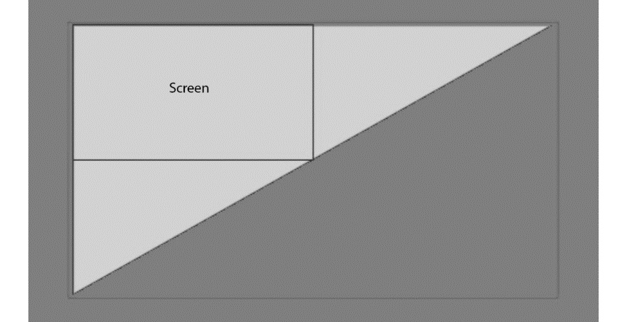
Figure 8.1 – Rendering a fullscreen triangle
These two OpenGL Shading Language (GLSL) functions will generate the OpenGL position and UV coordinates for a screen-covering triangle using just three values of the vertex index, going from 0 to 2:
vec4 fsTrianglePosition(int vtx) {
float x = -1.0 + float((vtx & 1) << 2);
float y = -1.0 + float((vtx & 2) << 1);
return vec4(x, y, 0.0, 1.0);
}
vec2 fsTriangleUV(int vtx) {
float u = (vtx == 1) ? 2.0 : 0.0; // 0, 2, 0
float v = (vtx == 2) ? 2.0 : 0.0; // 0, 0, 2
return vec2(u, v);
}
As an exercise, feel free to update the code using this code snippet. The triangle shader program should be invoked via glDrawArrays(GL_TRIANGLES, 0, 3).
Implementing shadow maps in OpenGL
As we learned from the previous chapters, we can render complex scenes with varying sets of materials, including physically based rendering (PBR) materials. While these techniques can produce very nice images, the visual realism of our scenes was severely lacking. Shadow mapping is one of the cornerstones of getting more realistic rendering results. In this recipe, we will give initial guidance on how to approach basic shadow mapping in OpenGL. Considering OpenGL is significantly less verbose compared to Vulkan, this recipe's main focus will be the shadow-mapping algorithm details, while its Vulkan counterpart is focused on the Vulkan application programming interface (API) details to get you started with shadow mapping.
Getting ready
The Chapter8/GL01_ShadowMapping demo application for this recipe implements basic steps for a projective shadow-mapping pipeline. It would be helpful to quickly go through the code before reading this recipe.
How to do it…
The projective shadow-mapping idea is quite straightforward. The scene is rendered from the light's point of view. The objects closest to the light are lit, while everything else is in the shadow. To determine the set of closest objects, a depth buffer can be used. To do that, we require a way to render our scene into an offscreen framebuffer.
The rendering process consists of three phases: calculating the light's projection and view matrices, rendering the entire scene from the light's point of view into an offscreen framebuffer, and rendering the entire scene again using the offscreen framebuffer's depth texture to apply the shadow map. Let's go through the C++ part of the code from Chapter8/GL01_ShadowMapping/src/main.cpp to see how this can be done:
- First, we need some per-frame data for our shaders. The view and proj matrices here are the standard view and projection matrices we already used earlier. The light matrix is the product of the light's view and projection matrices. This is sufficient for now because we are going to use only a single light in this recipe. The cameraPos field is a shortcut for the world-space camera position. The lightAngles field stores cosines of the light's inner and outer angles:
struct PerFrameData {
mat4 view;
mat4 proj;
mat4 light;
vec4 cameraPos;
vec4 lightAngles; // cos(inner), cos(outer)
vec4 lightPos;
};
- The light's view and projection matrices can be calculated from the following variables. Here, g_LightAngle is going to be the field-of-view angle of our light, g_LightInnerAngle defines the light's inner code, while g_LightXAngle and g_LightYAngle are the rotation angles around the X and Y axis respectively:
float g_LightAngle = 60.0f;
float g_LightInnerAngle = 10.0f;
float g_LightNear = 1.0f;
float g_LightFar = 20.0f;
float g_LightDist = 12.0f;
float g_LightXAngle = -1.0f;
float g_LightYAngle = -2.0f;
We now have the main() function with our standard GLApp object, which handles all the window-creation and input routines. All the shader programs loading happens right here. There are GL01_grid.* shaders for the grid rendering, GL01_scene.* for the scene rendering, and GL01_shadow.vert shaders for the shadow-map rendering:
int main(void) {
GLApp app;
GLShader shdGridVert( "data/shaders/chapter05/GL01_grid.vert");
GLShader shdGridFrag( "data/shaders/chapter05/GL01_grid.frag");
GLProgram progGrid(shdGridVert, shdGridFrag);
GLShader shdModelVert( "data/shaders/chapter08/GL01_scene.vert");
GLShader shdModelFrag( "data/shaders/chapter08/GL01_scene.frag");
GLProgram progModel(shdModelVert, shdModelFrag);
GLShader shdShadowVert( "data/shaders/chapter08/GL01_shadow.vert");
GLShader shdShadowFrag( "data/shaders/chapter08/GL01_shadow.frag");
GLProgram progShadowMap( shdShadowVert, shdShadowFrag);
We should create a uniform buffer for our per-frame values and set up some OpenGL state:
const GLsizeiptr kUniformBufferSize = sizeof(PerFrameData);
GLBuffer perFrameDataBuffer( kUniformBufferSize, nullptr, GL_DYNAMIC_STORAGE_BIT);
glBindBufferRange(GL_UNIFORM_BUFFER, 0, perFrameDataBuffer.getHandle(), 0, kUniformBufferSize);
glClearColor(1.0f, 1.0f, 1.0f, 1.0f);
glBlendFunc(GL_SRC_ALPHA, GL_ONE_MINUS_SRC_ALPHA);
Now, let's create a couple of meshes for our scene. The first one is our basic Duck mesh loaded from .gltf. The second one is just a plane that will receive a shadow. The plane is created right from the vertices. The GLMeshPVP class is used to store our meshes and feed them into OpenGL using a programmable-vertex-pulling (PVP) approach:
// 1. Duck
GLMeshPVP mesh("data/rubber_duck/scene.gltf");
GLTexture texAlbedoDuck(GL_TEXTURE_2D, "data/rubber_duck/textures/Duck_baseColor.png");
// 2. Plane
const std::vector<uint32_t> indices = { 0, 1, 2, 2, 3, 0 };
const std::vector<VertexData> vertices = { {vec3(-2, -2, 0), vec3(0,0,1), vec2(0,0)}, {vec3(-2, +2, 0), vec3(0,0,1), vec2(0,1)}, {vec3(+2, +2, 0), vec3(0,0,1), vec2(1,1)}, {vec3(+2, -2, 0), vec3(0,0,1), vec2(1,0)}, };
GLMeshPVP plane(indices, vertices.data(), uint32_t(sizeof(VertexData) * vertices.size()));
GLTexture texAlbedoPlane(GL_TEXTURE_2D, "data/ch2_sample3_STB.jpg");
const std::vector<GLMeshPVP*> meshesToDraw = { &mesh, &plane };
- Let's allocate a buffer to store model matrices for our meshes. We need to store only 2 matrices. We'll define our ImGui renderer and OpenGL canvas right here as well:
const mat4 m(1.0f);
GLBuffer modelMatrices(sizeof(mat4), value_ptr(m), GL_DYNAMIC_STORAGE_BIT);
glBindBufferBase(GL_SHADER_STORAGE_BUFFER, 2, modelMatrices.getHandle());
ImGuiGLRenderer rendererUI;
CanvasGL canvas;
- The shadow map is allocated using the GLFramebuffer class we explained previously in the Implementing offscreen rendering in OpenGL recipe. For a shadow map, the color buffer is not required per se. However, we set it to GL_RGBA8 to have a nice visualization of what is being rendered into the shadow map. The depth buffer is set to 24 bits and the entire framebuffer is 1024x1024 pixels:
GLFramebuffer shadowMap(1024, 1024, GL_RGBA8, GL_DEPTH_COMPONENT24);
That was the entire setup process necessary to render our scene. We skipped the keyboard and mouse-handling code because it is identical to all the previous demos. Now, let's take a look at the main loop and how everything is updated:
- We start by updating the camera positioner, recalculating the current time, and retrieving the actual application window dimensions:
while (!glfwWindowShouldClose(app.getWindow())) {
positioner.update(deltaSeconds, mouseState.pos, mouseState.pressedLeft);
const double newTimeStamp = glfwGetTime();
deltaSeconds = static_cast<float>(newTimeStamp - timeStamp);
timeStamp = newTimeStamp;
int width, height;
glfwGetFramebufferSize(app.getWindow(), &width, &height);
const float ratio = width / (float)height;
if (g_RotateModel)
angle += deltaSeconds;
- Before we can render the scene, we have to update the shader storage buffer object (SSBO) buffer with model-to-world matrices for each mesh. These are set based on the current rotation angle:
const mat4 scale = glm::scale( mat4(1.0f), vec3(3.0f));
const mat4 rot = glm::rotate(mat4(1.0f), glm::radians(-90.0f), vec3(1.0f, 0.0f, 0.0f));
const mat4 pos = glm::translate( mat4(1.0f), vec3(0.0f, 0.0f, +1.0f));
const mat4 m = glm::rotate(scale * rot * pos, angle, vec3(0.0f, 0.0f, 1.0f));
glNamedBufferSubData(modelMatrices.getHandle(), 0, sizeof(mat4), value_ptr(m));
- Let's calculate the light's view and projection matrices based on the global variables we control directly via ImGui:
const glm::mat4 rotY = glm::rotate( mat4(1.f), g_LightYAngle, glm::vec3(0, 1, 0));
const glm::mat4 rotX = glm::rotate( rotY, g_LightXAngle, glm::vec3(1, 0, 0));
const glm::vec4 lightPos = rotX * glm::vec4(0, 0, g_LightDist, 1.0f);
const mat4 lightProj = glm::perspective( glm::radians(g_LightAngle), 1.0f, g_LightNear, g_LightFar);
const mat4 lightView = glm::lookAt( glm::vec3(lightPos), vec3(0), vec3(0, 1, 0));
Rendering to the shadow map is similar to an ordinary scene rendering. We update the per-frame data so that our current view and projection matrices are set to represent the light's point of view. Before rendering, we clear the color and depth buffers of the shadow-map framebuffer using OpenGL's direct state access functions. The PerFrameData::light field is not used in the shadow shader, so we can leave this field uninitialized:
glEnable(GL_DEPTH_TEST);
glDisable(GL_BLEND);
const PerFrameData = { .view = lightView, .proj = lightProj, .cameraPos = glm::vec4(camera.getPosition(), 1.0f) };
glNamedBufferSubData( perFrameDataBuffer.getHandle(), 0, kUniformBufferSize, &perFrameData);
shadowMap.bind();
glClearNamedFramebufferfv(shadowMap.getHandle(), GL_COLOR, 0, glm::value_ptr(vec4(0.0f, 0.0f, 0.0f, 1.0f)));
glClearNamedFramebufferfi(shadowMap.getHandle(), GL_DEPTH_STENCIL, 0, 1.0f, 0);
progShadowMap.useProgram();
for (const auto& m : meshesToDraw)
m->drawElements();
shadowMap.unbind();
- Once the shadow map is ready, we should render the scene from an actual camera and apply the shadow map. As we mentioned in the Implementing offscreen rendering in OpenGL recipe, we have to restore the OpenGL viewport ourselves. The per-frame data is updated again, now using the data of our actual camera:
glViewport(0, 0, width, height);
glClear(GL_COLOR_BUFFER_BIT|GL_DEPTH_BUFFER_BIT);
const mat4 proj = glm::perspective( 45.0f, ratio, 0.5f, 5000.0f);
const mat4 view = camera.getViewMatrix();
const PerFrameData = { .view = view, .proj = proj, .light = lightProj * lightView, .cameraPos = glm::vec4(camera.getPosition(), 1.0f), .lightAngles = vec4( cosf(radians(0.5f * g_LightAngle)), cosf(radians(0.5f * (g_LightAngle-g_LightInnerAngle))), 1.0f, 1.0f), .lightPos = lightPos };
glNamedBufferSubData( perFrameDataBuffer.getHandle(), 0, kUniformBufferSize, &perFrameData);
- The scene-rendering shader uses two textures, one for the albedo texture and another for the shadow map:
const GLuint textures[] = { texAlbedoDuck.getHandle(), texAlbedoPlane.getHandle() };
glBindTextureUnit( 1, shadowMap.getTextureDepth().getHandle());
progModel.useProgram();
for (size_t i = 0; i != meshesToDraw.size(); i++)
{
glBindTextureUnit(0, textures[i]);
meshesToDraw[i]->drawElements();
}
- Once the main models are rendered, we should render the three-dimensional (3D) grid from the Implementing an infinite grid GLSL shader recipe of Chapter 5, Working with Geometry Data. On top of that, we render a debug view of our light's frustum using the CanvasGL class declared in shared/glFramework/LineCanvasGL.h:
glEnable(GL_BLEND);
progGrid.useProgram();
glDrawArraysInstancedBaseInstance( GL_TRIANGLES, 0, 6, 1, 0);
renderCameraFrustumGL(canvas, lightView, lightProj, vec4(0.0f, 1.0f, 0.0f, 1.0f));
canvas.flush();
- On top of the 3D scene, we render the ImGui user interface (UI), where we can change all the parameters of our shadow map. The mechanism was described in the Rendering a basic UI with Dear ImGui recipe from Chapter 2, Using Essential Libraries. The new functionality here is the calls to the imguiTextureWindowGL() function, which is our debug helper, to render the contents of an OpenGL texture in a separate ImGui window:
ImGuiIO& io = ImGui::GetIO();
io.DisplaySize = ImVec2((float)width, (float)height);
ImGui::NewFrame();
ImGui::Begin("Control", nullptr);
ImGui::Checkbox("Rotate", &g_RotateModel);
ImGui::End();
ImGui::Begin("Light parameters", nullptr);
ImGui::SliderFloat("Proj::Light angle", &g_LightAngle, 15.0f, 170.0f);
ImGui::SliderFloat("Proj::Light inner angle", &g_LightInnerAngle, 1.0f, 15.0f);
ImGui::SliderFloat("Proj::Near", &g_LightNear, 0.1f, 5.0f);
ImGui::SliderFloat("Proj::Far", &g_LightFar, 0.1f, 100.0f);
ImGui::SliderFloat("Pos::Dist", &g_LightDist, 0.5f, 100.0f);
ImGui::SliderFloat("Pos::AngleX", &g_LightXAngle, -3.15f, +3.15f);
ImGui::SliderFloat("Pos::AngleY", &g_LightYAngle, -3.15f, +3.15f);
ImGui::End();
imguiTextureWindowGL("Color", shadowMap.getTextureColor().getHandle());
imguiTextureWindowGL("Depth", shadowMap.getTextureDepth().getHandle());
ImGui::Render();
rendererUI.render( width, height, ImGui::GetDrawData());
app.swapBuffers();
}
return 0;
}
Rendering a texture into a separate ImGui window is very handy for debugging and can be done via the following snippet. Note that our texture coordinates are vertically flipped:
void imguiTextureWindowGL(
const char* title, uint32_t texId)
{
ImGui::Begin(title, nullptr);
const ImVec2 vMin = ImGui::GetWindowContentRegionMin();
const ImVec2 vMax = ImGui::GetWindowContentRegionMax();
ImGui::Image((void*)(intptr_t)texId, ImVec2(vMax.x - vMin.x, vMax.y - vMin.y), ImVec2(0.0f, 1.0f), ImVec2(1.0f, 0.0f) );
ImGui::End();
}
The demo application should render a shadowed scene, as in the following screenshot:
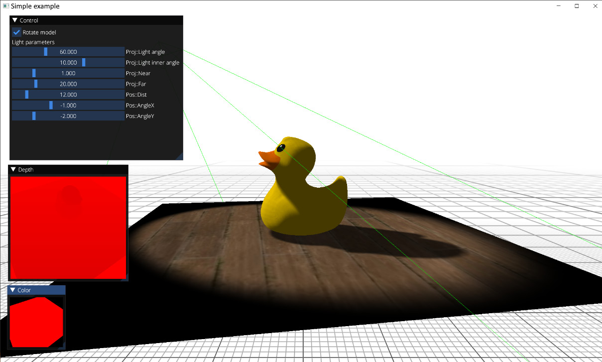
Figure 8.2 – Rendering a shadow-mapped duck
Let's take a look at the GLSL shaders necessary to render the shadow map and apply it to a scene. We have a set of vertex and fragment shaders necessary to render the scene into the shadow map, which can be found in the data/shaders/chapter08/GL01_shadow.frag and data/shaders/chapter08/GL01_shadow.vert files:
- The vertex shader reads vertex positions from an SSBO buffer and transforms them using the model matrix and the light's view and projection matrices:
#version 460 core
#include <data/shaders/chapter04/GLBufferDeclarations.h>
vec3 getPos(int i) {
return vec3(in_Vertices[i].p[0], in_Vertices[i].p[1], in_Vertices[i].p[2]);
}
void main() {
mat4 MVP = proj * view * in_ModelMatrices[gl_BaseInstance];
gl_Position = MVP * vec4(getPos(gl_VertexID), 1.0);
}
- The fragment shader trivially outputs the red color into the framebuffer. The main thing we care about here is the depth values:
#version 460 core
layout (location=0) out vec4 out_FragColor;
void main() {
out_FragColor = vec4(1.0, 0.0, 0.0, 1.0);
};
The resulting shadow map looks like this. Here, the content of the depth buffer is rendered as an R channel:

Figure 8.3 – A shadow map (cropped)
The remaining part of the application is a set of shaders used to apply this shadow map to our scene. They can be found in data/shaders/chapter08/GL01_scene.frag and data/shaders/chapter08/GL01_scene.vert. Let's take a look at the vertex shader:
- The vertex data retrieval from an SSBO buffer remains almost the same and just adds texture coordinates:
#version 460 core
#include <data/shaders/chapter08/GLBufferDeclarations.h>
layout(std140, binding = 0) uniform PerFrameData {
mat4 view;
mat4 proj;
mat4 light;
vec4 cameraPos;
vec4 lightAngles;
vec4 lightPos;
};
vec3 getPosition(int i) {
return vec3(in_Vertices[i].p[0], in_Vertices[i].p[1], in_Vertices[i].p[2]);
}
vec2 getTexCoord(int i) {
return vec2(in_Vertices[i].tc[0], in_Vertices[i].tc[1]);
}
struct PerVertex {
vec2 uv;
vec4 shadowCoord;
vec3 worldPos;
};
layout (location=0) out PerVertex vtx;
- We now have two sets of matrices. The main camera view and projection matrices are stored in the view and proj variables. We should use them directly to transform the vertex into the OpenGL clip space. The view and projection matrices representing the light are premultiplied and stored in the light variable. This matrix will transform our model*pos coordinates into the light's clip-space system. The OpenGL clip-space goes from -1.0 to +1.0 in all X, Y, and Z axes, making (0, 0, 0) the center point. However, when we sample a texture in OpenGL, the sampling coordinates have a center point at (0.5, 0.5, 0.5). To implement this remapping, we have to multiply the clip-space coordinates by 0.5 and translate them by 0.5. This linear transformation can be done manually, right after the light*model*pos multiplication. Instead, we can trivially construct a scaleBias matrix that will do everything in one multiplication. Transformed shadow coordinates are passed into the fragment shader:
const mat4 scaleBias = mat4( 0.5, 0.0, 0.0, 0.0, 0.0, 0.5, 0.0, 0.0, 0.0, 0.0, 0.5, 0.0, 0.5, 0.5, 0.5, 1.0);
void main() {
mat4 model = in_ModelMatrices[gl_BaseInstance];
mat4 MVP = proj * view * model;
vec3 pos = getPosition(gl_VertexID);
gl_Position = MVP * vec4(pos, 1.0);
vtx.uv = getTexCoord(gl_VertexID);
vtx.shadowCoord = scaleBias * light * model * vec4(pos, 1.0);
vtx.worldPos = (model * vec4(pos, 1.0)).xyz;
}
Note
One interesting remark is that in Vulkan, the clip-space Z axis goes from 0 to 1, making the scale-bias matrix different. This is a rather common mistake when porting existing OpenGL shaders to Vulkan. Another option is to use the ARB_clip_control extension to change OpenGL clip-space to use the 0..1 range and use the same matrix for both OpenGL and Vulkan:
const mat4 scaleBiasVulkan = mat4(
0.5, 0.0, 0.0, 0.0,
0.0, 0.5, 0.0, 0.0,
0.0, 0.0, 1.0, 0.0,
0.5, 0.5, 0.0, 0.1);
The fragment shader is more interesting. Let's take a look at what is happening there. As you may have already noticed from Figure 8.3, we have a soft shadow effect implemented using a percentage-closer filtering (PCF) technique. PCF is a method to reduce the aliasing of shadow mapping by averaging the results of multiple depth comparisons in the fragment shader. Here's how to do it:
- The fragment-shader prologue remains similar to our previous rendering, with the exception of an additional texture sampler, textureShadow:
#version 460 core
layout(std140, binding = 0) uniform PerFrameData {
mat4 view;
mat4 proj;
mat4 light;
vec4 cameraPos;
vec4 lightAngles;
vec4 lightPos;
};
struct PerVertex {
vec2 uv;
vec4 shadowCoord;
vec3 worldPos;
};
layout (location=0) in PerVertex vtx;
layout (location=0) out vec4 out_FragColor;
layout (binding = 0) uniform sampler2D texture0;
layout (binding = 1) uniform sampler2D textureShadow;
- The PCF() function performs averaging of multiple depth-comparison operations. The kernelSize argument is expected to be an odd number and defines the dimensions in texels of the kernelSize * kernelSize averaging square. Note that we average not the results of depth-map sampling at adjacent locations but the results of multiple comparisons of the depth value of the current fragment (in the light space) with sampled depth values obtained from the shadow map:
float PCF(
int kernelSize, vec2 shadowCoord, float depth) {
float size = 1.0 / float(textureSize(textureShadow, 0).x);
float shadow = 0.0;
int range = kernelSize / 2;
for (int v = -range; v <= range; v++)
for (int u = -range; u <= range; u++)
shadow += (depth >= texture(textureShadow, shadowCoord+size*vec2(u, v)).r) ? 1.0 : 0.0;
return shadow / (kernelSize * kernelSize);
}
- The shadowFactor() function hides all the shadowing machinery and returns a single shadow factor for the current fragment. The shadowCoord value is the position of the current fragment in the light's clip-space, interpolated from the vertex shader. We check if the fragment is within the -1.0...+1.0 clip-space Z range and call the PCF() function to evaluate the result. The depth value of the fragment is adjusted by depthBias to reduce shadow-acne artifacts while self-shadowing scene objects, which result from Z-fighting. This parameter is somewhat ad hoc and tricky and requires significant fine-tuning in real-world applications. A more sophisticated approach to fight shadow acne might be to modify bias values according to the slope of the surface. However, we will leave this here as it is, just for the sake of simplicity:
float shadowFactor(vec4 shadowCoord) {
vec4 shadowCoords4 = shadowCoord / shadowCoord.w;
if (shadowCoords4.z > -1.0 && shadowCoords4.z < 1.0)
{
float depthBias = -0.001;
float shadowSample = PCF( 13, shadowCoords4.xy, shadowCoords4.z + depthBias );
return mix(1.0, 0.3, shadowSample);
}
return 1.0;
}
- The lightFactor() function calculates the spot-light shadowing coefficient based on the inner and outer cone angles:
float lightFactor(vec3 worldPos) {
vec3 dirLight = normalize(lightPos.xyz - worldPos);
// the light is always looking at (0, 0, 0) vec3 dirSpot = normalize(-lightPos.xyz);
float rho = dot(-dirLight, dirSpot);
float outerAngle = lightAngles.x;
float innerAngle = lightAngles.y;
if (rho > outerAngle)
return smoothstep(outerAngle, innerAngle, rho);
return 0.0;
}
- With all the aforementioned helper functions in place, writing the main() function is trivial. We modulate the albedo color of the object with the shadow and spot-light factors:
void main() {
vec3 albedo = texture(texture0, vtx.uv).xyz;
out_FragColor = vec4(albedo * shadowFactor(vtx.shadowCoord) * lightFactor(vtx.worldPos), 1.0);
};
This concludes our basic OpenGL shadow-mapping example and the first use case of offscreen rendering. Let's switch gears back to the main topic of this chapter and implement some image-based postprocessing effects.
There's more…
The technique used to calculate the light's view and projection matrices described in this recipe is suitable only for spot and—partially —omnidirectional lights. For directional lights, which influence the entire visible scene, the values of view and projection matrices will depend on the geometry of the scene and how it intersects the main camera frustum. We will touch on this topic in Chapter 10, Advanced Rendering Techniques and Optimizations, and generate an outdoor shadow map for the Bistro scene.
In this recipe, we focused on the basic shadow-mapping math, while the actual OpenGL code was fairly trivial and easy to follow. In the subsequent recipes, we will demonstrate similar functionality via the Vulkan API. We also implemented a Vulkan version of this demo in the Chapter08/VK01_ShadowMapping project. Make sure you read the remaining Vulkan-related recipes in this chapter before digging into that source code.
Implementing SSAO in OpenGL
Screen Space Ambient Occlusion (SSAO) is an image-based technique to roughly approximate global illumination in real time. Ambient occlusion itself is a very crude approximation of global illumination. It can be thought of as the amount of open "sky" visible from a point on a surface and not occluded by any local adjacent geometry. In its simplest form, we can estimate this amount by sampling several points in the neighborhood of our point of interest and checking their visibility from the central point.
Getting ready
The Chapter8/GL02_SSAO demo application for this recipe implements basic steps for SSAO. Check out two previous recipes in this chapter, Implementing offscreen rendering in OpenGL and Implementing fullscreen quad rendering, before proceeding with this one.
How to do it...
Instead of tracing the depth buffer's height field, we use an even simpler approach where every selected neighborhood point is projected onto the depth buffer. The projected point is used as a potential occluder. The O(dZ) occlusion factor for such a point is calculated from the difference (dZ)between the projected depth value and the depth of the current fragment based on the following formula:
O(dZ)= (dZ > 0) ? 1/(1+dZ^2) : 0
These occlusion factors are averaged and used as the SSAO value for the current fragment. Before applying the resulting SSAO to the scene, it is blurred to reduce aliasing artifacts.
The SSAO shader operates purely on the depth buffer without any additional scene data, which makes this implementation a simple drop-in code snippet to start your own exploration of SSAO. Let's go through the C++ part of the code to see how to implement it:
- First, we need our usual data structure for per-frame data and SSAO parameters. The SSAO parameters are chosen arbitrarily and can be tweaked using the ImGui interface:
struct PerFrameData {
mat4 view;
mat4 proj;
vec4 cameraPos;
};
struct SSAOParams {
float scale_ = 1.0f;
float bias_ = 0.2f;
float zNear = 0.1f;
float zFar = 1000.0f;
float radius = 0.2f;
float attScale = 1.0f;
float distScale = 0.5f;
} g_SSAOParams;
- We reuse a single uniform buffer both for per-frame data for scene rendering and for SSAO parameters in fullscreen-rendering passes. Let's make sure that the size of the uniform buffer allocated for PerFrameData is large enough to store SSAOParams. Two ImGui-modifiable Boolean variables are used to enable the SSAO effect and blur:
static_assert(sizeof(SSAOParams) <= sizeof(PerFrameData));
bool g_EnableSSAO = true;
bool g_EnableBlur = true;
We skip all the keyboard and mouse-handling code because it is similar to the previous demos and jump straight into the main() function:
- First, we load all the GLSL shaders necessary for our rendering. The GL01_grid.* and GL01_mesh.* shaders are responsible for infinite grid rendering and mesh rendering respectively. They remain unchanged from the previous chapters:
int main(void) {
GLApp app;
GLShader shdGridVert( "data/shaders/chapter05/GL01_grid.vert");
GLShader shdGridFragt( "data/shaders/chapter05/GL01_grid.frag");
GLProgram progGrid(shdGridVert, shdGridFrag);
GLShader shaderVert( "data/shaders/chapter07/GL01_mesh.vert");
GLShader shaderFrag( "data/shaders/chapter07/GL01_mesh.frag");
GLProgram program(shaderVert, shaderFrag);
- The fullscreen quad vertex shader is shared by multiple fragment shaders. This vertex shader was described earlier, in the Implementing fullscreen quad rendering recipe. The GL02_SSAO.frag shader implements the SSAO effect itself. The GL02_SSAO_combine.frag shader combines the blurred SSAO buffer with the rendered scene. A pair of GL02_Blur*.frag shaders do a fullscreen separable Gaussian blur:
GLShader shdFullScreenQuadVert( "data/shaders/chapter08/GL02_FullScreenQuad.vert");
GLShader shdSSAOFrag( "data/shaders/chapter08/GL02_SSAO.frag");
GLShader shdCombineSSAOFrag( "data/shaders/chapter08/GL02_SSAO_combine.frag");
GLProgram progSSAO( shdFullScreenQuadVert, shdSSAOFrag);
GLProgram progCombineSSAO( shdFullScreenQuadVert, shdCombineSSAOFrag);
GLShader shdBlurXFrag( "data/shaders/chapter08/GL02_BlurX.frag");
GLShader shdBlurYFrag( "data/shaders/chapter08/GL02_BlurY.frag");
GLProgram progBlurX( shdFullScreenQuadVert, shdBlurXFrag);
GLProgram progBlurY( shdFullScreenQuadVerx, shdBlurYFrag);
- Let's allocate a buffer for our per-frame parameters, initialize some OpenGL state, and load a special texture for our SSAO shader and the Bistro scene. This is similar to the Bistro scene rendering from the previous chapter, Chapter 7, Graphics Rendering Pipeline. The additional SSAO texture will be created in the following snippet:
const GLsizeiptr kUniformBufferSize = sizeof(PerFrameData);
GLBuffer perFrameDataBuffer(kUniformBufferSize, nullptr, GL_DYNAMIC_STORAGE_BIT);
glBindBufferRange(GL_UNIFORM_BUFFER, kBufferIndex_PerFrameUniforms, perFrameDataBuffer.getHandle(), 0, kUniformBufferSize);
glClearColor(1.0f, 1.0f, 1.0f, 1.0f);
glBlendFunc(GL_SRC_ALPHA, GL_ONE_MINUS_SRC_ALPHA);
glEnable(GL_DEPTH_TEST);
GLTexture rotationPattern( GL_TEXTURE_2D, "data/rot_texture.bmp");
GLSceneData sceneData1(data/meshes/test.meshes", "data/meshes/test.scene", "data/meshes/test.materials");
GLSceneData sceneData2("data/meshes/test2.meshes", "data/meshes/test2.scene", "data/meshes/test2.materials");
GLMesh mesh1(sceneData1);
GLMesh mesh2(sceneData2);
ImGuiGLRenderer rendererUI;
positioner.maxSpeed_ = 1.0f;
double timeStamp = glfwGetTime();
float deltaSeconds = 0.0f;
- Before we can jump into the main() function, let's define offscreen render targets. Our scene will be rendered into framebuffer with dimensions equal to the size of our application's window. The SSAO effect goes into a framebuffer with a fixed size of 1024x1024 and no depth buffer. The same applies to the blurred render target. The ssao and blur framebuffers will be used in a ping-ping fashion to do a multipass Gaussian blur:
int width, height;
glfwGetFramebufferSize( app.getWindow(), &width, &height);
GLFramebuffer framebuffer( width, height, GL_RGBA8, GL_DEPTH_COMPONENT24);
GLFramebuffer ssao(1024, 1024, GL_RGBA8, 0);
GLFramebuffer blur(1024, 1024, GL_RGBA8, 0);
- The main() loop is quite straightforward. For simplicity, we omit the camera- and time-updating code from this listing. The first thing we do is clear framebuffer and update the view and projection matrices for the scene:
while (!glfwWindowShouldClose(app.getWindow()))
{
... skipped positioner/deltatime updates
glfwGetFramebufferSize( app.getWindow(), &width, &height);
const float ratio = width / (float)height;
glClearNamedFramebufferfv(framebuffer.getHandle(), GL_COLOR, 0, glm::value_ptr(vec4(0.0f, 0.0f, 0.0f, 1.0f)));
glClearNamedFramebufferfi(framebuffer.getHandle(), GL_DEPTH_STENCIL, 0, 1.0f, 0);
const mat4 proj = glm::perspective(45.0f, ratio, g_SSAOParams.zNear, g_SSAOParams.zFar);
const mat4 view = camera.getViewMatrix();
const PerFrameData = { .view = view, .proj = proj, .cameraPos = glm::vec4(camera.getPosition(), 1.0f)
};
glNamedBufferSubData( perFrameDataBuffer.getHandle(), 0, kUniformBufferSize, &perFrameData);
- Then, we should render the actual scene. We bind the framebuffer and render the Bistro meshes together with the infinite grid:
glDisable(GL_BLEND);
glEnable(GL_DEPTH_TEST);
framebuffer.bind();
// 1.1 Bistro
program.useProgram();
mesh1.draw(sceneData1);
mesh2.draw(sceneData2);
// 1.2 Grid
glEnable(GL_BLEND);
progGrid.useProgram();
glDrawArraysInstancedBaseInstance( GL_TRIANGLES, 0, 6, 1, 0);
framebuffer.unbind();
- Once the scene is rendered, we can use it to calculate the SSAO effect. The color buffer is cleared, SSAO parameters are uploaded into the uniform buffer object, and the ssao framebuffer is bound. We need to pass the depth texture of the main framebuffer into the SSAO shader, as well as a special two-dimensional (2D) texture with the rotation pattern. We will look into this in a moment while checking the GLSL code. A fullscreen quad is rendered via glDrawArrays(GL_TRIANGLES, 0, 6):
glDisable(GL_DEPTH_TEST);
glClearNamedFramebufferfv(ssao.getHandle(), GL_COLOR, 0, glm::value_ptr(vec4(0.0f, 0.0f, 0.0f, 1.0f)));
glNamedBufferSubData( perFrameDataBuffer.getHandle(), 0, sizeof(g_SSAOParams), &g_SSAOParams);
ssao.bind();
progSSAO.useProgram();
glBindTextureUnit( 0, framebuffer.getTextureDepth().getHandle());
glBindTextureUnit(1, rotationPattern.getHandle());
glDrawArrays(GL_TRIANGLES, 0, 6);
ssao.unbind();
After running this fragment, the ssao framebuffer will contain something similar to this:
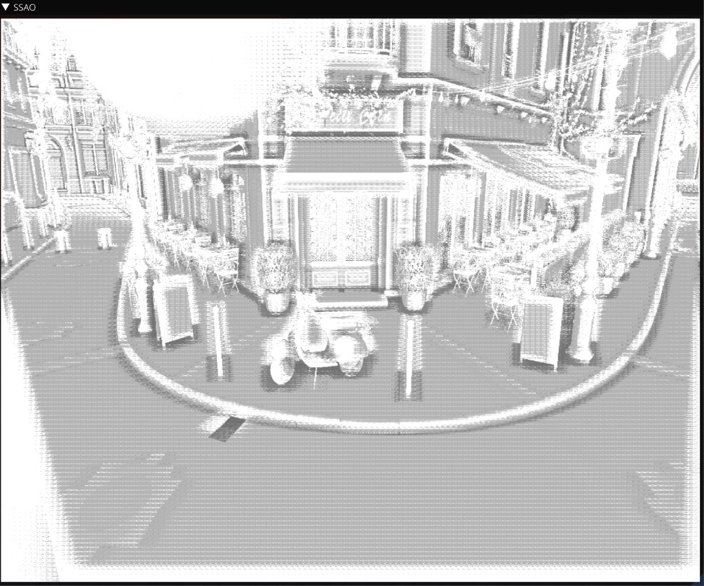
Figure 8.4 – Raw SSAO buffer
- While the result in Figure 8.4 is already useful, it can be improved significantly by simple blurring. We run a simple separable Gaussian blur effect in two passes. The first pass blurs in the horizontal direction, and the second one blurs the image vertically. Here, the blur and ssao render targets are used in a ping-ping fashion. This is handy because if the blur effect is turned off via ImGui, the content of the original ssao framebuffer remains intact:
if (g_EnableBlur) {
blur.bind();
progBlurX.useProgram();
glBindTextureUnit( 0, ssao.getTextureColor().getHandle());
glDrawArrays(GL_TRIANGLES, 0, 6);
blur.unbind();
ssao.bind();
progBlurY.useProgram();
glBindTextureUnit( 0, blur.getTextureColor().getHandle());
glDrawArrays(GL_TRIANGLES, 0, 6);
ssao.unbind();
}
The blurred SSAO image should look like this:

Figure 8.5 – Blurred SSAO buffer
- All the intermediate steps are now done, and we can combine these auxiliary framebuffers into a final image. Let's restore the OpenGL viewport and render the final fullscreen pass using color textures from the main offscreen framebuffer and ssao. Should SSAO be disabled, we can use the OpenGL 4.5 functionality to blit or copy our offscreen framebuffer right into the app's main window:
glViewport(0, 0, width, height);
if (g_EnableSSAO) {
progCombineSSAO.useProgram();
glBindTextureUnit( 0, framebuffer.getTextureColor().getHandle());
glBindTextureUnit( 1, ssao.getTextureColor().getHandle());
glDrawArrays(GL_TRIANGLES, 0, 6);
}
else {
glBlitNamedFramebuffer( framebuffer.getHandle(), 0, 0, 0, width, height, 0, 0, width, height, GL_COLOR_BUFFER_BIT, GL_LINEAR);
}
- To conclude the C++ implementation of the effect, here's the ImGui snippet to control SSAO parameters. Note how some parameters can be disabled in the UI based on the value of g_EnableSSAO. More details regarding the ImGui item flags and how to control rendering styles can be found at https://github.com/ocornut/imgui/issues/1889#issuecomment-398681105. Debug texture rendering with ImGui was explained in the previous recipe, Implementing shadow maps in OpenGL:
ImGuiIO& io = ImGui::GetIO();
io.DisplaySize = ImVec2((float)width, (float)height);
ImGui::NewFrame();
ImGui::Begin("Control", nullptr);
ImGui::Checkbox("Enable SSAO", &g_EnableSSAO);
ImGui::PushItemFlag( ImGuiItemFlags_Disabled, !g_EnableSSAO);
ImGui::PushStyleVar(ImGuiStyleVar_Alpha, ImGui::GetStyle().Alpha * g_EnableSSAO ? 1.f : 0.2f);
ImGui::Checkbox("Enable blur", &g_EnableBlur);
ImGui::SliderFloat( "SSAO scale", &g_SSAOParams.scale_, 0.0f,2.0f);
ImGui::SliderFloat( "SSAO bias", &g_SSAOParams.bias_, 0.0f, 0.3f);
ImGui::PopItemFlag();
ImGui::PopStyleVar();
ImGui::Separator();
ImGui::SliderFloat("SSAO radius", &g_SSAOParams.radius, 0.05f, 0.5f);
ImGui::SliderFloat("SSAO attenuation scale", &g_SSAOParams.attScale, 0.5f, 1.5f);
ImGui::SliderFloat("SSAO distance scale", &g_SSAOParams.distScale, 0.0f, 1.0f);
ImGui::End();
imguiTextureWindowGL("Color", framebuffer.getTextureColor().getHandle());
imguiTextureWindowGL("Depth", framebuffer.getTextureDepth().getHandle());
imguiTextureWindowGL("SSAO", ssao.getTextureColor().getHandle());
ImGui::Render();
rendererUI.render( width, height, ImGui::GetDrawData());
app.swapBuffers();
}
return 0;
}
This demo application should render the following image:
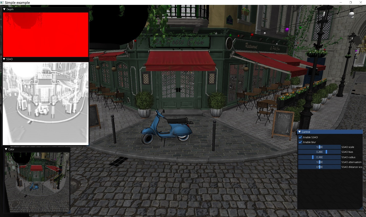
Figure 8.6 – SSAO demo
We have now got an overall feel of the rendering process and can start looking into the GLSL shaders code.
The GL02_SSAO.frag fragment shader takes input as the scene-depth buffer and the rotation vectors texture that contains 16 random vec3 vectors. This technique was proposed by Crytek in the early days of real-time SSAO algorithms:

Figure 8.7 – Random vectors' texture (4x4 pixels)
- We start by defining a table with offsets to 8 points to sample around the current fragment and all the SSAO parameters we receive from the C++ code:
#version 460 core
layout(location = 0) in vec2 uv;
layout(location = 0) out vec4 outColor;
layout(binding = 0) uniform sampler2D texDepth;
layout(binding = 1) uniform sampler2D texRotation;
const vec3 offsets[8] = vec3[8]( vec3(-0.5,-0.5,-0.5), vec3( 0.5, -0.5,-0.5), vec3(-0.5, 0.5,-0.5), vec3( 0.5, 0.5,-0.5), vec3(-0.5, -0.5, 0.5), vec3( 0.5,-0.5, 0.5), vec3(-0.5, 0.5, 0.5), vec3( 0.5, 0.5, 0.5));
layout(std140, binding = 0) uniform SSAOParams {
float scale;
float bias;
float zNear;
float zFar;
float radius;
float attScale;
float distScale;
};
- We should retrieve the depth value from texDepth and convert it to eye space:
void main() {
float size = 1.0 / float(textureSize(texDepth, 0).x);
float Z = (zFar * zNear) / (texture(texDepth, uv).x * (zFar-zNear)-zFar);
- Then, we take the aforementioned random rotation's 4x4 texture, tile it across the size of our entire framebuffer, and sample a vec3 value from it, corresponding to the current fragment. This value becomes a normal vector to a random plane. In the loop, we reflect each of our vec3 offsets from this plane, producing a new rSample sampling point in the neighborhood of our area of interest defined by the radius value. The zSample depth value corresponding to this point is sampled from the depth texture and immediately converted to eye space. After that, this value is zero-clipped and scaled using an ad hoc distScale parameter controllable from ImGui:
vec3 plane = texture( texRotation, uv * size / 4.0).xyz - vec3(1.0);
float att = 0.0;
for ( int i = 0; i < 8; i++ ) {
vec3 rSample = reflect(offsets[i], plane);
float zSample = texture( texDepth, uv + radius*rSample.xy / Z ).x;
zSample = (zFar*zNear) / (zSample * (zFar-zNear) - zFar);
float dist = max(zSample - Z, 0.0) / distScale;
- The occl distance difference is scaled by an arbitrarily selected weight. Further averaging is done using quadratic attenuation, according to the O(dZ)= (dZ > 0) ? 1/(1+dZ^2) : 0 formula. The final scale factor, attScale, is controlled from ImGui:
float occl = 15.0 * max(dist * (2.0 - dist), 0.0);
att += 1.0 / (1.0 + occl*occl);
}
att = clamp(att*att/64. + 0.45, 0., 1.) * attScale;
outColor = vec4(vec3(att), 1.0);
}
While this method does not get close to the best SSAO implementations, it is very simple with regard to its input parameters and can operate just on a naked depth buffer.
Let's quickly look into how to blur the SSAO values. The set of blurring fragment shaders is located in shaders/chapter08/GL02_BlurX.frag and shaders/chapter08/GL02_BlurY.frag. Their difference is just the direction of the blur, so we can show only one:
- There is a table containing weights for Gaussian blur. They add up to 1.0:
#version 460 core
layout(location = 0) in vec2 uv;
layout(location = 0) out vec4 outColor;
layout(binding = 0) uniform sampler2D texSSAO;
const vec2 gaussFilter[11] = vec2[]( vec2(-5.0, 3.0/133.0), vec2(-4.0, 6.0/133.0), vec2(-3.0, 10.0/133.0), vec2(-2.0, 15.0/133.0), vec2(-1.0, 20.0/133.0), vec2( 0.0, 25.0/133.0), vec2( 1.0, 20.0/133.0), vec2( 2.0, 15.0/133.0), vec2( 3.0, 10.0/133.0), vec2( 4.0, 6.0/133.0), vec2( 5.0, 3.0/133.0));
- Averaging is trivially done in a for loop:
void main() {
vec3 color = vec3(0.0);
float scale = 1.0 / textureSize(texSSAO, 0).x;
for ( int i = 0; i < 11; i++ ) {
vec2 coord = vec2( uv.x + gaussFilter[i].x * scale, uv.y);
color += textureLod( texSSAO, coord, 0).rgb * gaussFilter[i].y;
}
outColor = vec4(color, 1.0);
}
To combine the SSAO effect with the rendered scene, the following GLSL fragment shader should be used: shaders/chapter08/GL02_SSAO_combine.frag. The scale and bias values are controlled from ImGui:
#version 460 core
layout(location = 0) in vec2 uv;
layout(location = 0) out vec4 outColor;
layout(binding = 0) uniform sampler2D texScene;
layout(binding = 1) uniform sampler2D texSSAO;
layout(std140, binding = 0) uniform SSAOParams {
float scale;
float bias;
};
void main() {
vec4 color = texture(texScene, uv);
float ssao = clamp(texture(texSSAO, uv).r + bias, 0.0, 1.0);
outColor = vec4(mix(color, color * ssao, scale).rgb, 1.0);
}
With all this knowledge, you should be able to add a similar SSAO effect to your rendering engine.
In the next recipe, we will learn how to implement a more complex postprocessing scheme for HDR rendering and tone mapping.
There's more...
While running the demo, you may have noticed that the SSAO effect behaves somewhat weirdly on transparent surfaces. That is quite understandable since our transparency rendering is done via punch-through transparency whereby a part of transparent surface pixels is discarded proportionally to the transparency value. These holes expose the depth values beneath the transparent surface, hence our SSAO implementation works partially. In a real-world rendering engine, you might want to calculate the SSAO effect after the opaque objects have been fully rendered and before any transparent objects influence the depth buffer.
Implementing HDR rendering and tone mapping
In all our previous examples, the resulting color values in the framebuffer were clamped between 0.0 and 1.0. Furthermore, we used 1 byte per color component, making only 256 shades of brightness possible, which means the ratio between the darkest and the brightest regions in the image cannot be larger than 256:1. This might seem sufficient for many applications, but what happens if we have a really bright region illuminated by the Sun or multiple lights? Everything will be clamped at 1.0, and any additional information in the higher values of brightness, or luminance, will be lost. These HDR brightness values can be remapped back into a Low Dynamic Range (LDR) 0..1 interval using a tone-mapping technique.
Getting ready
The source code for this demo is located in Chapter8/GL03_HDR/src/main.cpp.
How to do it...
To implement HDR rendering, we need to store HDR values in framebuffers. This can be done using our existing GLFramebuffer framework and providing appropriate OpenGL color texture formats. OpenGL has a GL_RGBA16F 16-bit floating-point red-green-blue (RGB) format that can be used for rendering.
Once the scene is rendered into a floating-point framebuffer, we can calculate the average luminance value of the HDR image and use it to guide the tone-mapping calculation. Furthermore, we can detect high values of luminance in the image and use those areas to simulate the bloom of real-world cameras. See https://en.wikipedia.org/wiki/Bloom_(shader_effect) for more on this.
Let's go through the C++ code to understand the entire pipeline:
- First, we need a data structure for per-frame data and HDR parameters. Similar to the previous recipe, we reuse our uniform buffer for both, so let's make sure its size is sufficiently large:
struct PerFrameData {
mat4 view;
mat4 proj;
vec4 cameraPos;
};
struct HDRParams {
float exposure_ = 0.9f;
float maxWhite_ = 1.17f;
float bloomStrength_ = 1.1f;
} g_HDRParams;
static_assert( sizeof(HDRParams) <= sizeof(PerFrameData));
- The main() function has a typical layout and starts by loading all the necessary shaders. The main scene is rendered via the GL03_scene_IBL.* set of shaders, which apply image-space lighting to the Bistro model, similar to how it was done in Chapter 6, Physically Based Rendering Using the glTF2 Shading Model, with the exception that we use only the diffuse part of image-based lighting (IBL) this time. We will look into this when studying the GLSL code:
int main(void) {
GLApp app;
GLShader shdGridVert( "data/shaders/chapter05/GL01_grid.vert");
GLShader shdGridFrag( "data/shaders/chapter05/GL01_grid.frag");
GLProgram progGrid(shdGridVert, shdGridFra);
GLShader shdFullScreenQuadVert( "data/shaders/chapter08/GL02_FullScreenQuad.vert");
GLShader shdCombineHDR( "data/shaders/chapter08/GL03_HDR.frag");
GLProgram progCombineHDR( shdFullScreenQuadVert, shdCombineHDR);
GLShader shdBlurX( "data/shaders/chapter08/GL02_BlurX.frag");
GLShader shdBlurY( "data/shaders/chapter08/GL02_BlurY.frag");
GLProgram progBlurX( shdFullScreenQuadVertex, shdBlurX);
GLProgram progBlurY( shdFullScreenQuadVertex, shdBlurY);
GLShader shdToLuminance( "data/shaders/chapter08/GL03_ToLuminance.frag");
GLProgram progToLuminance( shdFullScreenQuadVertex, shdToLuminance);
GLShader shdBrightPass( "data/shaders/chapter08/GL03_BrightPass.frag");
GLProgram progBrightPass( shdFullScreenQuadVertex, shdBrightPass);
GLShader shaderVert( "data/shaders/chapter08/GL03_scene_IBL.vert");
GLShader shaderFrag( "data/shaders/chapter08/GL03_scene_IBL.frag");
GLProgram program(shaderVert, shaderFrag);
- Allocate a uniform buffer object, set up the OpenGL state, and load Bistro meshes. Again, the keyboard and mouse-handling code is skipped here:
const GLsizeiptr kUniformBufferSize = sizeof(PerFrameData);
GLBuffer perFrameDataBuffer(kUniformBufferSize, nullptr, GL_DYNAMIC_STORAGE_BIT);
glBindBufferRange(GL_UNIFORM_BUFFER, kBufferIndex_PerFrameUniforms, perFrameDataBuffer.getHandle(), 0, kUniformBufferSize);
glClearColor(1.0f, 1.0f, 1.0f, 1.0f);
glBlendFunc(GL_SRC_ALPHA, GL_ONE_MINUS_SRC_ALPHA);
glEnable(GL_DEPTH_TEST);
GLSceneData sceneData1("data/meshes/test.meshes", "data/meshes/test.scene", "data/meshes/test.materials");
GLSceneData sceneData2("data/meshes/test2.meshes", "data/meshes/test2.scene", "data/meshes/test2.materials");
GLMesh mesh1(sceneData1);
GLMesh mesh2(sceneData2);
- Let's create some offscreen framebuffers to store intermediate data. There is a fullscreen framebuffer to store a freshly rendered scene. Note the GL_RGBA16F color format here, which can store color values outside the 0..1 range. The luminance framebuffer is used to convert the rendered scene into grayscale luminance values, and the GL_R16F single-channel format is used for this purpose. Besides that, we create two ping-pong framebuffers for a multipass bloom:
int width, height;
glfwGetFramebufferSize( app.getWindow(), &width, &height);
GLFramebuffer framebuffer(width, height, GL_RGBA16F, GL_DEPTH_COMPONENT24);
GLFramebuffer luminance(64, 64, GL_R16F, 0);
GLFramebuffer brightPass(256, 256, GL_RGBA16F, 0);
GLFramebuffer bloom1(256, 256, GL_RGBA16F, 0);
GLFramebuffer bloom2(256, 256, GL_RGBA16F, 0);
- The luminance texture should be downscaled to the size of 1x1 texels before it can be used as an average luminance value. We might do this with multiple subsequent rendering passes into framebuffers of diminishing sizes and a downscaling fragment shader, giving you precise control over filtering. We decided to go a simpler way and use the last automatically generated MIP-level of the luminance texture as the final 1x1 average luminance texture. Starting from OpenGL 4.3, there is functionality to create texture views, which allows developers to create references to elements of existing textures. The following snippet creates a view into the last mip-level, 6, of our 64x64 luminance texture. Setting the texture swizzle mode allows us to automatically sample this GL_R16F texture as if it were a GL_RGBA16F texture, propagating the R channel into all RGBA values. This trick eases compatibility with our ImGui debug rendering:
GLuint luminance1x1;
glGenTextures(1, &luminance1x1);
glTextureView(luminance1x1, GL_TEXTURE_2D, luminance.getTextureColor().getHandle(), GL_R16F, 6, 1, 0, 1);
const GLint Mask[] = { GL_RED, GL_RED, GL_RED, GL_RED };
glTextureParameteriv( luminance1x1, GL_TEXTURE_SWIZZLE_RGBA, Mask);
Because our mesh-rendering shader applies IBL to the scene, let's render this IBL cube map as a sky box. The cube map for this demo was downloaded from https://hdrihaven.com/hdri/?h=immenstadter_horn. The irradiance map was generated using our Util01_FilterEnvmap tool from Chapter 6, Physically Based Rendering Using the glTF2 Shading Model:
GLTexture envMap(GL_TEXTURE_CUBE_MAP, "data/immenstadter_horn_2k.hdr");
GLTexture envMapIrradiance(GL_TEXTURE_CUBE_MAP, "data/immenstadter_horn_2k_irradiance.hdr");
GLShader shdCubeVertex( "data/shaders/chapter08/GL03_cube.vert");
GLShader shdCubeFragment( "data/shaders/chapter08/GL03_cube.frag");
GLProgram progCube(shdCubeVertex, shdCubeFragment);
GLuint dummyVAO;
glCreateVertexArrays(1, &dummyVAO);
const GLuint pbrTextures[] = { envMap.getHandle(), envMapIrradiance.getHandle() };
glBindTextures(5, 2, pbrTextures);
ImGuiGLRenderer rendererUI;
- After all these preparations, we can enter the main loop. We start by clearing the main framebuffer, updating the view and projection matrices, and refreshing the content of the uniform buffer object:
while (!glfwWindowShouldClose(app.getWindow())) {
...camera positioner/time update code skipped here
int width, height;
glfwGetFramebufferSize( app.getWindow(), &width, &height);
const float ratio = width / (float)height;
glClearNamedFramebufferfv(framebuffer.getHandle(), GL_COLOR, 0, glm::value_ptr(vec4(0.0f, 0.0f, 0.0f, 1.0f)));
glClearNamedFramebufferfi(framebuffer.getHandle(), GL_DEPTH_STENCIL, 0, 1.0f, 0);
const mat4 p = glm::perspective(45.0f, ratio, 0.1f, 1000.0f);
const mat4 view = camera.getViewMatrix();
const PerFrameData = { .view = view, .proj = p, .cameraPos = glm::vec4(camera.getPosition(), 1.0f) };
glNamedBufferSubData( perFrameDataBuffer.getHandle(), 0, kUniformBufferSize, &perFrameData);
- Let's render our sky box, the Bistro mesh, and the infinite grid. To simplify dealing with transparency, we render the sky box before everything else:
glDisable(GL_BLEND);
glEnable(GL_DEPTH_TEST);
framebuffer.bind();
// 1.0 Cube map
progCube.useProgram();
glBindTextureUnit(1, envMap.getHandle());
glDepthMask(false);
glBindVertexArray(dummyVAO);
glDrawArrays(GL_TRIANGLES, 0, 36);
glDepthMask(true);
// 1.1 Bistro
program.useProgram();
mesh1.draw(sceneData1);
mesh2.draw(sceneData2);
// 1.2 Grid
glEnable(GL_BLEND);
progGrid.useProgram();
glDrawArraysInstancedBaseInstance( GL_TRIANGLES, 0, 6, 1, 0);
framebuffer.unbind();
- After we are done with rendering into the main framebuffer, we can start our postprocessing pipeline. Bright regions are extracted from the rendered image and stored in the brightPass framebuffer. The fragment shader used is chapter08/GL03_BrightPass.frag:
glDisable(GL_BLEND);
glDisable(GL_DEPTH_TEST);
brightPass.bind();
progBrightPass.useProgram();
glBindTextureUnit( 0, framebuffer.getTextureColor().getHandle());
glDrawArrays(GL_TRIANGLES, 0, 6);
brightPass.unbind();
Then, the main framebuffer is downscaled to 64x64 pixels and converted to luminance using the chapter08/GL03_ToLuminance.frag shader. After the luminance pass has finished, we automatically update the mipmap chain of the luminance framebuffer's color texture. This provides correct data for the luminance1x1 texture view:
luminance.bind();
progToLuminance.useProgram();
glBindTextureUnit( 0, framebuffer.getTextureColor().getHandle());
glDrawArrays(GL_TRIANGLES, 0, 6);
luminance.unbind();
glGenerateTextureMipmap( luminance.getTextureColor().getHandle());
- Let's switch back to the bright areas of the scene and run a multipass separable Gaussian filter to simulate the bloom effect. The bright areas will be heavily blurred and start leaking into the adjacent pixels, producing nice halos. We built the data into the bloom2 framebuffer and apply 4 passes of horizontal and vertical blur:
glBlitNamedFramebuffer( brightPass.getHandle(), bloom2.getHandle(), 0, 0, 256, 256, 0, 0, 256, 256, GL_COLOR_BUFFER_BIT, GL_LINEAR);
for (int i = 0; i != 4; i++) {
// Horizontal blur
bloom1.bind();
progBlurX.useProgram();
glBindTextureUnit( 0, bloom2.getTextureColor().getHandle());
glDrawArrays(GL_TRIANGLES, 0, 6);
bloom1.unbind();
// Vertical blur
bloom2.bind();
progBlurY.useProgram();
glBindTextureUnit( 0, bloom1.getTextureColor().getHandle());
glDrawArrays(GL_TRIANGLES, 0, 6);
bloom2.unbind();
}
- Now, everything is ready to do tone mapping. Let's restore the viewport, update the uniform buffer, and render a fullscreen quad with our chapter08/GL03_HDR.frag tone-mapping shader. The input textures for our shader are the HDR scene, the average luminance value, and the blurred bloom:
glViewport(0, 0, width, height);
if (g_EnableHDR) {
glNamedBufferSubData( perFrameDataBuffer.getHandle(), 0, sizeof(g_HDRParams), &g_HDRParams);
progCombineHDR.useProgram();
glBindTextureUnit( 0, framebuffer.getTextureColor().getHandle());
glBindTextureUnit(1, luminance1x1);
glBindTextureUnit( 2, bloom2.getTextureColor().getHandle());
glDrawArrays(GL_TRIANGLES, 0, 6);
}
else {
glBlitNamedFramebuffer(framebuffer.getHandle(), 0, 0, 0, width, height, 0, 0, width, height, GL_COLOR_BUFFER_BIT, GL_LINEAR);
}
- Last, but not least, here's the ImGui snippet to control all HDR values we use in this demo. Note how the luminance texture is rendered in red because it has the GL_R16F color format, while the average 1x1 luminance is rendered as grayscale because of the texture-swizzle mode we set:
ImGui::GetIO().DisplaySize = ImVec2((float)width, (float)height);
ImGui::NewFrame();
ImGui::Begin("Control", nullptr);
ImGui::Checkbox("Enable HDR", &g_EnableHDR);
ImGui::PushItemFlag(ImGuiItemFlags_Disabled, !g_EnableHDR);
ImGui::PushStyleVar( ImGuiStyleVar_Alpha, ImGui::GetStyle().Alpha * g_EnableHDR ? 1.0f : 0.2f);
ImGui::Separator();
ImGui::Text("Average luminance:");
ImGui::Image( (void*)(intptr_t)luminance1x1, ImVec2(128, 128), ImVec2(0.0f, 1.0f), ImVec2(1.0f, 0.0f));
ImGui::Separator();
ImGui::SliderFloat("Exposure", &g_HDRParams.exposure_, 0.1f, 2.0f);
ImGui::SliderFloat("Max White", &g_HDRParams.maxWhite_, 0.5f, 2.0f);
ImGui::SliderFloat("Bloom strength", &g_HDRParams.bloomStrength_, 0.0f, 2.0f);
ImGui::PopItemFlag();
ImGui::PopStyleVar();
ImGui::End();
imguiTextureWindowGL("Color", framebuffer.getTextureColor().getHandle());
imguiTextureWindowGL("Luminance", luminance.getTextureColor().getHandle());
imguiTextureWindowGL("Bright Pass", brightPass.getTextureColor().getHandle());
imguiTextureWindowGL( "Bloom", bloom2.getTextureColor().getHandle());
ImGui::Render();
rendererUI.render( width, height, ImGui::GetDrawData());
app.swapBuffers();
}
- We created the texture view manually. Don't forget to delete it:
glDeleteTextures(1, &luminance1x1);
return 0;
}
The C++ part was rather short, and the overall pipeline looked quite similar to the previous recipe. Now, let's look into the GLSL shaders code.
Let's quickly recap on the chapter08/GL03_scene_IBL.frag mesh rendering shader and check the modifications we used here to apply diffuse IBL to the scene.
- We start with declaring data structures. The material data format from the previous chapter, Chapter 7, Graphics Rendering Pipeline, is reused:
#version 460 core
#extension GL_ARB_bindless_texture : require
#extension GL_ARB_gpu_shader_int64 : enable
#include <data/shaders/chapter07/MaterialData.h>
layout(std140, binding = 0) uniform PerFrameData {
mat4 view;
mat4 proj;
vec4 cameraPos;
};
layout(std430, binding = 2)
restrict readonly buffer Materials {
MaterialData in_Materials[];
};
layout (location=0) in vec2 v_tc;
layout (location=1) in vec3 v_worldNormal;
layout (location=2) in vec3 v_worldPos;
layout (location=3) in flat uint matIdx;
layout (location=0) out vec4 out_FragColor;
- We declare two cube map textures and a bidirectional reflectance distribution function (BRDF) lookup table (LUT), similar to our PBR demo from Chapter 6, Physically Based Rendering Using the glTF2 Shading Model. However, only the irradiance map is actually required to implement a diffuse IBL. The other two samplers are declared to allow compilation of the included data/shaders/chapter06/PBR.sp file, which accesses these samplers:
layout (binding = 5) uniform samplerCube texEnvMap;
layout (binding = 6) uniform samplerCube texEnvMapIrradiance;
layout (binding = 7) uniform sampler2D texBRDF_LUT;
#include <data/shaders/chapter07/AlphaTest.h>
#include <data/shaders/chapter06/PBR.sp>
- Material data is fetched from a buffer. The albedo texture and a normal map are sampled, if present, and the bump mapping effect is computed. This is similar to how the Bistro mesh was rendered in the previous chapter, Chapter 7, Graphics Rendering Pipeline:
void main() {
MaterialData mtl = in_Materials[matIdx];
vec4 albedo = mtl.albedoColor_;
vec3 normalSample = vec3(0.0, 0.0, 0.0);
// fetch albedo
if (mtl.albedoMap_ > 0)
albedo = texture(sampler2D( unpackUint2x32(mtl.albedoMap_)), v_tc);
if (mtl.normalMap_ > 0)
normalSample = texture(sampler2D( unpackUint2x32(mtl.normalMap_)), v_tc).xyz;
runAlphaTest(albedo.a, mtl.alphaTest_);
// world-space normal
vec3 n = normalize(v_worldNormal);
// normal mapping: skip missing normal maps
if (length(normalSample) > 0.5)
n = perturbNormal( n, normalize(cameraPos.xyz - v_worldPos.xyz), normalSample, v_tc);
- The main difference happens when it comes to lighting. Instead of computing the dot(N, L) diffuse factor, we use the diffuse part of the glTF2 physically based shading (PBS) IBL lighting model:
vec3 f0 = vec3(0.04);
vec3 diffuseColor = albedo.rgb * (vec3(1.0) - f0);
vec3 diffuse = texture( texEnvMapIrradiance, n.xyz).rgb * diffuseColor;
out_FragColor = vec4(diffuse, 1.0);
};
This shader renders a fully shaded Bistro scene into the 16-bit framebuffer. Let's look into how to extract bright areas of the rendered image using the chapter08/GL03_BrightPass.frag shader and convert the scene to luminance using chapter08/GL03_ToLuminance.frag:
- The GL03_BrightPass.frag shader uses a dot product to convert red-green-blue-alpha (RGBA) values to luminance. Output the values only if the result is brighter than 1.0:
#version 460 core
layout(location = 0) in vec2 uv;
layout(location = 0) out vec4 outColor;
layout(binding = 0) uniform sampler2D texScene;
void main() {
vec4 color = texture(texScene, uv);
float luminance = dot(color, vec4(0.33, 0.34, 0.33, 0.0));
outColor = luminance >= 1.0 ? color : vec4(vec3(0.0), 1.0);
}
- The GL03_ToLuminance.frag shader outputs the result of a similar dot product directly into the framebuffer. Note the different weights used here. This is a very rough approximation that runs pretty well for our demo:
#version 460 core
layout(location = 0) in vec2 uv;
layout(location = 0) out vec4 outColor;
layout(binding = 0) uniform sampler2D texScene;
void main() {
vec4 color = texture(texScene, uv);
float luminance = dot(color, vec4(0.3, 0.6, 0.1, 0.0));
outColor = vec4(vec3(luminance), 1.0);
}
The tone-mapping process is implemented in the chapter08/GL03_HDR.frag shader. Let's go through its GLSL code:
- Three texture samplers are required—the main framebuffer with the HDR scene, the 1x1 average luminance texture, and the blurred bloom texture. The parameters of the HDR tone-mapping function are controlled by ImGui:
#version 460 core
layout(location = 0) in vec2 uv;
layout(location = 0) out vec4 outColor;
layout(binding = 0) uniform sampler2D texScene;
layout(binding = 1) uniform sampler2D texLuminance;
layout(binding = 2) uniform sampler2D texBloom;
layout(std140, binding = 0) uniform HDRParams {
float exposure;
float maxWhite;
float bloomStrength;
};
- The tone mapping is done using the Extended Reinhard tone-mapping operator. The maxWhite value is tweaked to represent the maximal brightness value in the scene. Everything brighter than this value will be mapped to 1.0:
vec3 Reinhard2(vec3 x) {
return (x * (1.0 + x / (maxWhite * maxWhite))) / (1.0 + x);
}
- This function is applied to the HDR color values in the following way. After the tone mapping is done, the bloom texture can be added on top of everything:
void main() {
vec3 color = texture(texScene, uv).rgb;
vec3 bloom = texture(texBloom, uv).rgb;
float avgLuminance = texture(texLuminance, vec2(0.5, 0.5)).x;
float midGray = 0.5;
color *= exposure * midGray / (avgLuminance + 0.001);
color = Reinhard2(color);
outColor = vec4(color + bloomStrength * bloom, 1.0);
}
This demo renders the Bistro scene with a sky box, as in the following screenshot. Note where Bloom causes the bright sky color to bleed over the edges of the buildings:
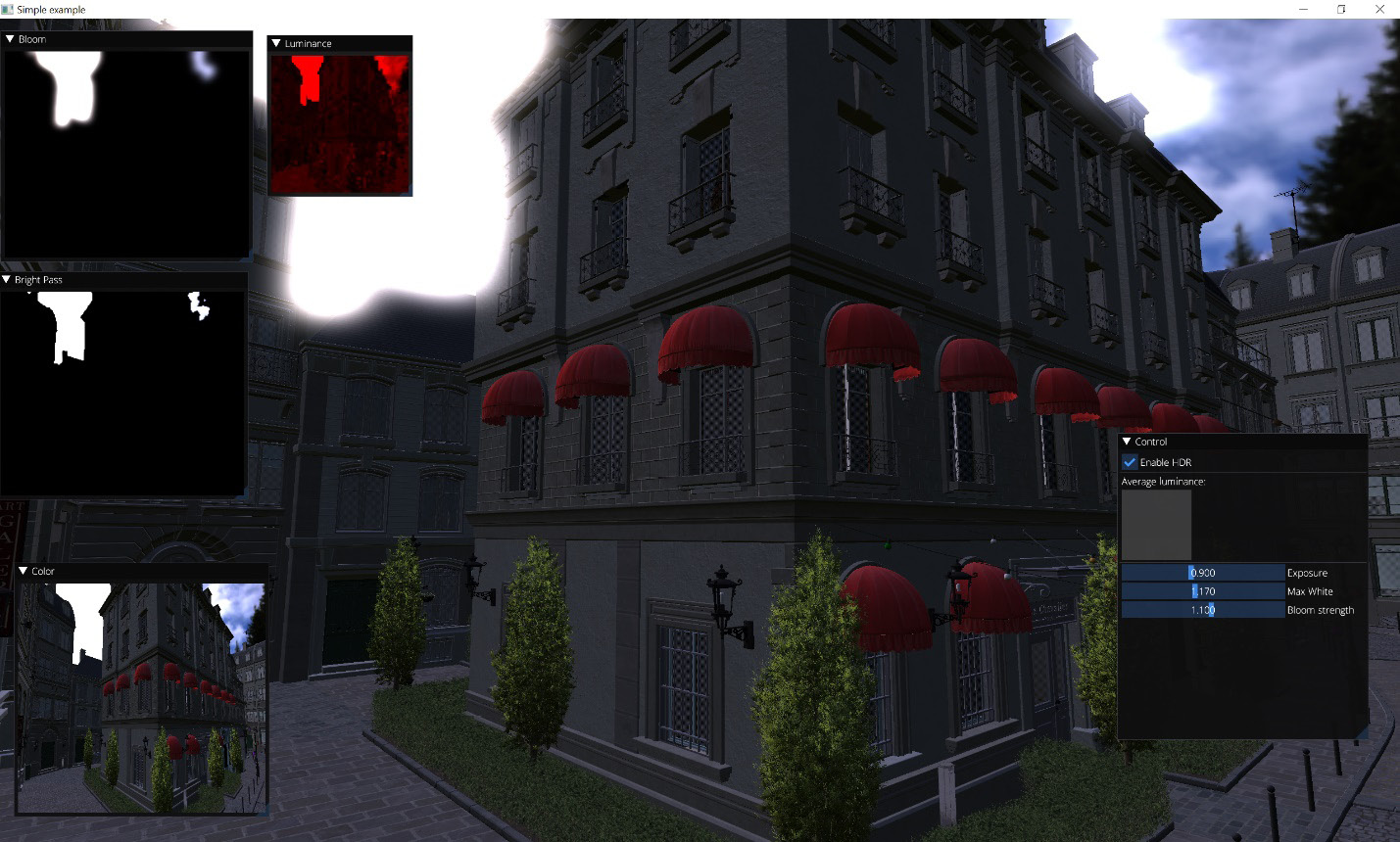
Figure 8.8 – A tone-mapped HDR scene
When you move the camera around, you can see how the scene brightness is adjusted based on the current luminance. If you look at the sky, you will be able to see the details in bright areas, but the rest of the scene will become dark. If you look at the dark corners of the buildings, the sky will go into white. The overall exposure can be manually shifted using the ImGui slider.
One downside of this approach is that changes in exposure happen momentarily. You look at a different area of the scene, and in the next frame, you have the exposure instantly changed. This is not how human vision works in reality. It takes time for our eyes to adapt from bright to dark areas. In the next recipe, we will learn how to extend the HDR postprocessing pipeline and simulate light adaptation.
There's more...
Strictly speaking, applying a tone-mapping operator directly to RGB channel values is very crude. The more correct model would be to tone-map the luminance and then apply it back to RGB values. However, for many practical purposes, this simple approximation is sufficient.
Implementing HDR light adaptation
In the previous recipe, Implementing HDR rendering and tone mapping, we learned how to do the basic stages of an HDR pipeline. Let's extend this and add a realistic light-adaptation process to simulate how the human-vision system adapts to bright light.
Getting ready
Make sure you go through the previous recipe, Implementing HDR rendering and tone mapping, before taking on this one.
The source code for this demo is located at Chapter8/GL04_HDR_Adaptation.
How to do it...
In order to add a light-adaptation step to our previous HDR tone-mapping demo, let's introduce a few additions to the C++ code:
- First, we need a new parameter to control the light-adaptation speed:
struct HDRParams {
float exposure_ = 0.9f;
float maxWhite_ = 1.17f;
float bloomStrength_ = 1.1f;
float adaptationSpeed_ = 0.1f;
} g_HDRParams;
static_assert( sizeof(HDRParams) <= sizeof(PerFrameData));
- The initialization code should load yet another shader. This one is a compute shader that does an adaptation of luminance based on the new average luminance value in the rendered scene and the previous luminance value used for tone mapping:
int main(void) {
GLApp app;
...
GLShader shdAdaptation( "data/shaders/chapter08/GL03_Adaptation.comp");
GLProgram progAdaptation(shdAdaptation);
- In addition to the render targets we already have, let's introduce two more textures, luminance1 and luminance2. Those will be used as ping-pong images in the light-adaptation compute shader. For simplicity, we declare the luminance render targets to be GL_RGBA16F and omit any texture-swizzling modes:
GLFramebuffer framebuffer(width, height, GL_RGBA16F, GL_DEPTH_COMPONENT24);
GLFramebuffer luminance(64, 64, GL_RGBA16F, 0);
GLFramebuffer brightPass(256, 256, GL_RGBA16F, 0);
GLFramebuffer bloom1(256, 256, GL_RGBA16F, 0);
GLFramebuffer bloom2(256, 256, GL_RGBA16F, 0);
GLuint luminance1x1;
glGenTextures(1, &luminance1x1);
glTextureView(luminance1x1, GL_TEXTURE_2D, luminance.getTextureColor().getHandle(), GL_RGBA16F, 6, 1, 0, 1);
GLTexture luminance1( GL_TEXTURE_2D, 1, 1, GL_RGBA16F);
GLTexture luminance2( GL_TEXTURE_2D, 1, 1, GL_RGBA16F);
const GLTexture* luminances[] = { &luminance1, &luminance2 };
- The first luminance texture is initialized with a really bright value, 50.0, right from the get-go. This will simulate a situation when our vision is adapting from a bright area to a darker one, giving a nice effect when the application starts:
const vec4 brightPixel(vec3(50.0f), 1.0f);
glTextureSubImage2D(luminance1.getHandle(), 0, 0, 0, 1, 1, GL_RGBA, GL_FLOAT, glm::value_ptr(brightPixel));
- In the main loop, we pass our HDR parameters to shaders, downscale the scene, and convert it to luminance, similar to the previous recipe, Implementing HDR rendering and tone mapping, and then apply the light-adaptation compute shader:
while (!glfwWindowShouldClose(app.getWindow())) {
...
// pass HDR params to shaders
glNamedBufferSubData( perFrameDataBuffer.getHandle(), 0, sizeof(g_HDRParams), &g_HDRParams);
// 2.1 Downscale and convert to luminance
luminance.bind();
progToLuminance.useProgram();
glBindTextureUnit( 0, framebuffer.getTextureColor().getHandle());
glDrawArrays(GL_TRIANGLES, 0, 6);
luminance.unbind();
glGenerateTextureMipmap( luminance.getTextureColor().getHandle());
The OpenGL memory model requires the insertion of explicit memory barriers to make sure that a compute shader can access correct data in a texture after it was written by a render pass. More details regarding the OpenGL memory model can be found at https://www.khronos.org/opengl/wiki/Memory_Model:
glMemoryBarrier( GL_SHADER_IMAGE_ACCESS_BARRIER_BIT);
progAdaptation.useProgram();
There are two ways to bind our textures to compute shader-image units. Either way is possible but in the first case, all the access modes will be automatically set to GL_READ_WRITE:
#if 0
const GLuint imageTextures[] = { luminances[0]->getHandle(), luminance1x1, luminances[1]->getHandle() };
glBindImageTextures(0, 3, imageTextures);
#else
glBindImageTexture(0, luminances[0]->getHandle(), 0, GL_TRUE, 0, GL_READ_ONLY, GL_RGBA16F);
glBindImageTexture(1, luminance1x1, 0, GL_TRUE, 0, GL_READ_ONLY, GL_RGBA16F);
glBindImageTexture(2, luminances[1]->getHandle(), 0, GL_TRUE, 0, GL_WRITE_ONLY, GL_RGBA16F);
#endif
- The compute shader is invoked on a single texel. One more memory barrier is required to make sure that the subsequent rendering code fetches the texture data that has already been properly updated by the compute shader:
glDispatchCompute(1, 1, 1);
glMemoryBarrier(GL_TEXTURE_FETCH_BARRIER_BIT);
The further C++ workflow remains intact, except for the site where we pass the average luminance texture into the final tone-mapping shader. Instead of using luminance1x1 directly, we should use one of the ping-pong luminance textures we created earlier:
glViewport(0, 0, width, height);
if (g_EnableHDR) {
progCombineHDR.useProgram();
glBindTextureUnit( 0, framebuffer.getTextureColor().getHandle());
glBindTextureUnit( 1, luminances[1]->getHandle());
glBindTextureUnit( 2, bloom2.getTextureColor().getHandle());
glDrawArrays(GL_TRIANGLES, 0, 6);
}
else {
...
}
... ImGui code skipped ...
- At the end of the main loop, we only need to swap the ping-pong buffers for the current and adapted luminances:
std::swap(luminances[0], luminances[1]);
}
glDeleteTextures(1, &luminance1x1);
return 0;
}
Those are all the changes necessary for our previous C++ code. The addition to the GLSL part of our HDR pipeline is the light-adaptation compute shader. This is located in the file shaders/chapter08/GL03_Adaptation.comp folder and is described next:
- The local workgroup size is (1, 1, 1), as we are dealing with just a single texel. The input images correspond to the previous luminance from the imgLuminancePrev rendered scene, the imgLuminanceCurr current luminance from the first ping-ping luminance texture, and the imgLuminanceAdapted output adapted luminance going into the second ping-pong texture:
#version 460 core
layout(local_size_x = 1, local_size_y = 1, local_size_z = 1) in;
layout(rgba16f, binding=0) uniform readonly image2D imgLuminancePrev;
layout(rgba16f, binding=1) uniform readonly image2D imgLuminanceCurr;
layout(rgba16f, binding=2) uniform writeonly image2D imgLuminanceAdapted;
layout(std140, binding = 0) uniform HDRParams {
float exposure;
float maxWhite;
float bloomStrength;
float adaptationSpeed;
};
- The main() function loads a single texel from each input image and computes the adapted luminance using the Lavg=Lavg+(L−Lavg)*(1−exp(c*dt*adaptationSpeed)) modified the 8.1.4.3 Adaptation equation from https://google.github.io/filament/Filament.md.html#mjx-eqn-adaptation. Here, dt=30.0 is the delta time since the previous frame, which we hardcoded for the sake of simplicity, and adaptationSpeed is a parameter that controls the light-adaptation rate. A single texel representing the adapted luminance is written to the output texture using imageStore():
void main() {
float lumPrev = imageLoad(imgLuminancePrev, ivec2(0, 0)).x;
float lumCurr = imageLoad(imgLuminanceCurr, ivec2(0, 0)).x;
float newAdaptation = lumPrev + (lumCurr-lumPrev) * (1.0 - pow(0.98, 30.0 * adaptationSpeed));
imageStore(imgLuminanceAdapted, ivec2(0, 0), vec4(vec3(newAdaptation), 1.0));
}
This technique enables a pleasing smooth light-adaptation effect when the scene luminance changes abruptly. Try running the Chapter8/GL04_HDR_Adaptation demo application and pointing the camera at bright areas in the sky and dark areas in the corners. The light-adaptation speed can be user-controlled from ImGui, as in the following screenshot:
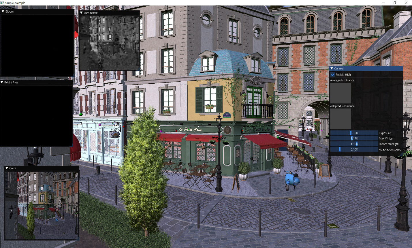
Figure 8.9 – An HDR tone-mapped scene with light adaptation
Now, let's switch from OpenGL to Vulkan and learn how to deal with postprocessing effects with the more verbose API.
There's more...
HDR rendering is a huge topic, and we barely scratched its surface in this chapter. If you want to learn more advanced state-of-the-art HDR lighting techniques, we recommend watching the Game Developers Conference (GDC) 2010 session Uncharted 2: HDR Lighting by John Hable: https://www.gdcvault.com/play/1012351/Uncharted-2-HDR.
Writing postprocessing effects in Vulkan
In the previous recipes of this chapter, we learned about some popular image-based postprocessing effects and how to implement them in OpenGL. Now, we can focus on the Vulkan API to approach one solution to a similar problem.
In this recipe, we use the Renderer class from the Working with rendering passes recipe from the previous chapter, Chapter 7, Graphics Rendering Pipeline, to wrap a sequence of rendering operations in a single composite item. A helper class to perform fullscreen per-pixel image processing is also presented here.
Getting ready...
Make sure you read the previous OpenGL-related recipes in this chapter as they focus on the algorithm flow, and from this point on, we will be focused on the Vulkan API details and how to wrap them in a manageable way.
How to do it...
Most of the effects in this chapter use a number of rendering passes to calculate the output image. The CompositeRenderer class is a collection of renderers acting as one renderer:
- The code follows the composite software design pattern (https://en.wikipedia.org/wiki/Composite_pattern). It provides an interface by delegating the operation to each object in a collection of objects implementing the Renderer interface:
struct CompositeRenderer: public Renderer {
CompositeRenderer(VulkanRenderContext& c)
: Renderer(c) {}
- The internal loop over the renderers in fillCommandBuffer() is the same as in VulkanApp::composeFrame(). Individual renderers can have their own render passes and output framebuffers. We delegate all the actual work to these renderers, which is done in r.renderer.fillCommandBuffer():
void fillCommandBuffer(VkCommandBuffer cmdBuffer, size_t currentImage, VkFramebuffer fb1 = VK_NULL_HANDLE, VkRenderPass rp1 = VK_NULL_HANDLE) override
{
for (auto& r: renderers_) {
if (!r.enabled_) continue;
VkRenderPass rp = rp1;
VkFramebuffer fb = fb1;
if (r.renderer_.renderPass_.handle != VK_NULL_HANDLE)
rp = r.renderer_.renderPass_.handle;
if (r.renderer_.framebuffer_ != VK_NULL_HANDLE)
fb = r.renderer_.framebuffer_;
r.renderer_.fillCommandBuffer( cmdBuffer, currentImage, fb, rp);
}
}
- The updateBuffers() method also follows the composite design pattern and redirects buffer updates to individual internal renderers. The only field this class has is the list of Renderer-derived objects wrapped in the RenderItem structure to allow a No-Raw-Pointers implementation. As a reminder, the RenderItem structure contains a reference to the Renderer-derived class and allows the use of std::vector::emplace_back() to fill the list of renderers without triggering copy constructors and without dynamic allocations:
void updateBuffers(size_t currentImage) override {
for (auto& r: renderers_)
r.renderer_.updateBuffers(currentImage);
}
protected:
std::vector<RenderItem> renderers_;
};
We now have a method to produce a sequence of postprocessing operations, but we have not yet defined a postprocessing operation itself. Let's approach this task step by step.
The postprocessing framework has a single operation as its building block: the fullscreen quadrangle rendered with a shader that takes some textures (possibly, other framebuffers) as an input:
- First, let's introduce a short helper class, OffscreenMeshRenderer, for single mesh rendering into an offscreen framebuffer:
struct OffscreenMeshRenderer: public BufferProcessor {
OffscreenMeshRenderer( VulkanRenderContext& ctx, VulkanBuffer uniformBuffer, const std::pair<BufferAttachment, BufferAttachment>& meshBuffer, const std::vector<TextureAttachment>& usedTextures, const std::vector<VulkanTexture>& outputs, const std::vector<const char*>& shaderFiles, bool firstPass = false)
: BufferProcessor(ctx, DescriptorSetInfo { .buffers = { uniformBufferAttachment(uniformBuffer, 0, 0, VK_SHADER_STAGE_VERTEX_BIT | VK_SHADER_STAGE_FRAGMENT_BIT), meshBuffer.first, meshBuffer.second, }, .textures = usedTextures }, outputs, shaderFiles, meshBuffer.first.size, ctx.resources.addRenderPass(outputs, RenderPassCreateInfo { .clearColor_ = firstPass, .clearDepth_ = firstPass, .flags_ = (uint8_t)((firstPass ? eRenderPassBit_First : eRenderPassBit_OffscreenInternal) | eRenderPassBit_Offscreen) })) {}};
- The VulkanShaderProcessor class derived from Renderer implements a generic fillCommandBuffer() method that calls a custom shader. The indexBufferSize parameter has a default value of 24, which is the number of bytes to store six 32-bit integers. This is the size of an index array for two triangles that form a single quadrangle. The reason this class exposes this parameter to the user is simple: rendering a complex 3D mesh instead of a single quadrangle is performed in the same way. This class generalizes our approach to mesh rendering from Chapter 3, Getting Started with OpenGL and Vulkan. In our sample application, we use the OffscreenMeshRenderer derived class to render a single mesh using different effects:
struct VulkanShaderProcessor: public Renderer {
VulkanShaderProcessor(VulkanRenderContext& ctx, const PipelineInfo& pInfo, const DescriptorSetInfo& dsInfo, const std::vector<const char*>& shaders, const std::vector<VulkanTexture>& outputs, uint32_t indexBufferSize = 6 * 4, RenderPass screenRenderPass = RenderPass())
: Renderer(ctx)
, indexBufferSize(indexBufferSize) {
- Fullscreen processors need only a single descriptor set, which is created using the dsInfo structure passed via parameters. At the end of initialization, a graphics pipeline with a suitable render pass is created:
descriptorSetLayout_ = ctx.resources.addDescriptorSetLayout(dsInfo);
descriptorSets_ = { ctx.resources.addDescriptorSet( ctx.resources.addDescriptorPool(dsInfo), descriptorSetLayout_) };
ctx.resources.updateDescriptorSet( descriptorSets_[0], dsInfo);
initPipeline(shaders, initRenderPass( pInfo, outputs, screenRenderPass, ctx.screenRenderPass_NoDepth));
}
- The fillCommandBuffer() method uses the stored size of an index buffer. The data part of the class stores the size of the index buffer for the vkCmdDraw() command:
void fillCommandBuffer(VkCommandBuffer cmdBuffer, size_t currentImage, VkFramebuffer fb = VK_NULL_HANDLE, VkRenderPass rp = VK_NULL_HANDLE) override
{
beginRenderPass((rp != VK_NULL_HANDLE) ? rp : renderPass_.handle, (fb != VK_NULL_HANDLE) ? fb : framebuffer_, cmdBuffer, 0);
vkCmdDraw(cmdBuffer, indexBufferSize / sizeof(uint32_t), 1, 0, 0);
vkCmdEndRenderPass(cmdBuffer);
}
private:
uint32_t indexBufferSize;
};
Let's check how to render a fullscreen quad using this approach:
- The QuadProcessor class is a helper class that specifies the default shader for VulkanShaderProcessor. The vertex shader is always the same, but the fragment shader specified as a parameter contains custom postprocessing per-pixel logic. If there are no offscreen render targets, we use a screen render pass:
struct QuadProcessor: public VulkanShaderProcessor { QuadProcessor(VulkanRenderContext& ctx, const DescriptorSetInfo& dsInfo, const std::vector<VulkanTexture>& outputs, const char* shaderFile):
VulkanShaderProcessor( ctx, ctx.pipelineParametersForOutputs(outputs), dsInfo, std::vector<const char*>{ "data/shaders/chapter08/quad.vert", shaderFile }, outputs, 6 * 4, outputs.empty() ? ctx.screenRenderPass : RenderPass())
{}
};
- The vertex shader to render a screen-size quadrangle is similar to the cube shader from Chapter 3, Getting Started with OpenGL and Vulkan. Since we use PVP, there is no need to bind an input vertex array. We get away with declaring indices, vertex coordinates, and texture coordinates as shader constants:
layout(location = 0) out vec2 texCoord;
int indices[6] = int[] ( 0, 1, 2, 0, 2, 3 );
vec2 positions[4] = vec2[]( vec2(1.0, -1.0), vec2(1.0, 1.0), vec2(-1.0, 1.0), vec2(-1.0, -1.0));
vec2 texcoords[4] = vec2[]( vec2(1.0, 1.0), vec2(1.0, 0.0), vec2(0.0, 0.0), vec2(0.0, 1.0));
- The shader fetches an index and outputs a position along with the interpolated texture coordinate:
void main() {
int idx = indices[gl_VertexIndex];
gl_Position = vec4(positions[idx], 0.0, 1.0);
texCoord = texcoords[idx];
}
A postprocessed image can be output to the screen using the QuadRenderer class from the previous chapter, Chapter 7, Graphics Rendering Pipeline, or the new class QuadProcessor described previously.
Implementing SSAO in Vulkan
Earlier in this chapter, we learned how to implement SSAO in OpenGL and went through every detail of our code. This recipe shows how to implement this technique using the Vulkan API.
We will skip the GLSL shaders here because they are almost identical to those for OpenGL, and rather focus on the C++ parts of the code that deal with Vulkan.
Getting ready...
Make sure you read the Implementing SSAO in OpenGL recipe to understand the data flow of our SSAO implementation and the previous recipe, Writing postprocessing effects in Vulkan, to have a good grasp of the basic classes we use in our Vulkan wrapper.
The source code for this demo can be found in Chapter08/VK02_SSAO.
How to do it...
The SSAOProcessor class wraps multiple QuadProcessor instances into a single streamlined reusable pipeline for SSAO rendering:
- A set of GLSL shaders for SSAO rendering is passed as arguments to the QuadProcessor instances:
struct SSAOProcessor: public CompositeRenderer {
SSAOProcessor( VulkanRenderContext&ctx, VulkanTexture colorTex, VulkanTexture depthTex, VulkanTexture outputTex)
: CompositeRenderer(ctx)
, rotateTex(ctx.resources.loadTexture2D( "data/rot_texture.bmp"))
, SSAOTex(ctx.resources.addColorTexture( SSAOWidth, SSAOHeight))
, SSAOBlurXTex(ctx.resources.addColorTexture( SSAO_W, SSAO_H))
, SSAOBlurYTex(ctx.resources.addColorTexture( SSAO_W, SSAO_H))
, SSAO(ctx, { .textures = { fsTextureAttachment(depthTex), fsTextureAttachment(rotateTex) } }, { SSAOTex }, "data/shaders/chapter08/SSAO.frag")
, BlurX(ctx, { .textures = { fsTextureAttachment(SSAOTex) } }, { SSAOBlurXTex }, "data/shaders/chapter08/SSAOBlurX.frag")
, BlurY(ctx, { .textures = { fsTextureAttachment(SSAOBlurXTex) } }, { SSAOBlurYTex }, "data/shaders/chapter08/SSAOBlurY.frag")
, SSAOFinal(ctx, { .textures = { fsTextureAttachment(colorTex), fsTextureAttachment(SSAOBlurYTex) } }, { outputTex }, "data/shaders/chapter08/SSAOFinal.frag")
{
- The only code we need in the constructor fills the renderers_ container. None of these renderers performs depth buffer writes, so the second parameter, useDepth, should be set to false:
renderers_.emplace_back(SSAO, false);
renderers_.emplace_back(BlurX, false);
renderers_.emplace_back(BlurY, false);
renderers_.emplace_back(SSAOFinal, false);
}
- For debugging purposes, we expose access to intermediate textures. The private: section declares all the intermediate textures and individual QuadProcessor instances. You already know the principle of their operation from the Implementing SSAO in OpenGL recipe:
VulkanTexture getSSAO() const { return SSAOTex; }
VulkanTexture getBlurX() const
{ return SSAOBlurXTex; }
VulkanTexture getBlurY() const
{ return SSAOBlurYTex; }
private:
VulkanTexture rotateTex;
VulkanTexture SSAOTex, SSAOBlurXTex, SSAOBlurYTex;
QuadProcessor SSAO, BlurX, BlurY, SSAOFinal;
};
Here is a snippet from the source code of Chapter08/VK02_SSAO/src/main.cpp that uses the SSAOProcessor class presented previously:
- The data is initialized similarly to the Vulkan recipes from the previous chapter, Chapter 7, Graphics Rendering Pipeline:
struct MyApp: public CameraApp {
MyApp()
: CameraApp(-80, -80)
, envMap(ctx_.resources.loadCubeMap(envMapFile))
, irrMap(ctx_.resources.loadCubeMap(irrMapFile))
, colorTex(ctx_.resources.addColorTexture())
, depthTex(ctx_.resources.addDepthTexture())
, finalTex(ctx_.resources.addColorTexture())
, sceneData(ctx_, "data/meshes/test.meshes", "data/meshes/test.scene", "data/meshes/test.materials", envMap, irrMap)
, multiRenderer(ctx_, sceneData, "data/shaders/chapter07/VK01.vert", "data/shaders/chapter07/VK01.frag", { colorTex, depthTex }
, ctx_.resources.addRenderPass({colorTex, depthTex}
, RenderPassCreateInfo { .clearColor_ = true, .clearDepth_ = true, .flags_ = eRenderPassBit_First | eRenderPassBit_Offscreen }))
, SSAO(ctx_, colorTex, depthTex, finalTex)
, quads(ctx_, { colorTex, depthTex, finalTex })
, imgui(ctx_)
{
onScreenRenderers_.emplace_back(multiRenderer);
onScreenRenderers_.emplace_back(SSAO);
onScreenRenderers_.emplace_back(quads, false);
onScreenRenderers_.emplace_back(imgui, false);
}
- The drawing code is straightforward:
void draw3D() override {
const mat4 m1 = glm::rotate( mat4(1.f), glm::pi<float>(), vec3(1, 0, 0));
multiRenderer.setMatrices(getDefaultProjection(), camera.getViewMatrix(), m1);
quads.clear();
quads.quad(-1.0f, -1.0f, 1.0f, 1.0f, 2);
}
private:
VulkanTexture envMap, irrMap;
VulkanTexture colorTex, depthTex, finalTex;
VKSceneData sceneData;
MultiRenderer;
SSAOProcessor SSAO;
QuadRenderer quads;
GuiRenderer imgui;
};
We can now add the SSAO effect to different Vulkan demos just by moving the instance of SSAOProcessor. While this might be pretty neat for learning and demonstration, it is far from the most performant solution and can be difficult to synchronize in postprocessing pipelines that include tens of different effects. We will touch on this topic a bit more in Chapter 10, Advanced Rendering Techniques and Optimizations.
Implementing HDR rendering in Vulkan
Just recently, in the previous recipe, we learned how to implement one OpenGL postprocessing effect in Vulkan, and here, we will learn how to implement HDR rendering and tone mapping using the Vulkan API.
Getting ready…
Make sure you read the Implementing HDR rendering and tone mapping recipe to understand the HDR rendering pipeline, and the Writing postprocessing effects in Vulkan recipe to have a good grasp of the basic classes we use in our Vulkan postprocessors.
The complete source code for this recipe can be found in Chapter8/VK03_HDR.
How to do it...
We define an HDRPostprocessor class derived from QuadProcessor that performs a per-pixel tone-mapping operation on an input framebuffer. The tone-mapping parameter pointers can be tweaked by the application code in the UI window.
One C++-related subtlety must be addressed in the initialization of the HDRProstprocessor class:
- The base class constructor is called before any field initializers, but at this point, we already need to pass the tonemapUniforms buffer field as a parameter for the constructor of QuadProcessor. To tackle this, we declare a bufferAllocator() function, which takes a reference to VulkanBuffer, allocates this buffer, and immediately returns the created instance. The code for this function is given after the HDRPostprocessor class. The postprocessor requires an input color framebuffer in 16-bit floating-point format to allow greater-than-one values and a single output texture. The base class constructor is called with a descriptor set that has a pre-initialized uniform buffer with tone-mapping parameters and a single input texture. The output framebuffer and the tone-mapping shader name are passed directly to QuadProcessor:
struct HDRPostprocessor: public QuadProcessor {
HDRPostprocessor(VulkanRenderContext& ctx, VulkanTexture input, VulkanTexture output)
: QuadProcessor(ctx, DescriptorSetInfo { .buffers = { uniformBufferAttachment( bufferAllocator(ctx.resources, tonemapUniforms_, sizeof(UniformBuffer)), 0, 0, VK_SHADER_STAGE_FRAGMENT_BIT) },
.textures = { fsTextureAttachment(input) } }, { output }, "data/shaders/chapter08/VK_ToneMap.frag")
{}
- The overridden updateBuffers() method uploads the uniform buffer into the graphics processing unit (GPU). As an alternative, a permanent mapping to the ubo field can be created in the class constructor:
void updateBuffers(size_t currentImage) override {
uploadBufferData( ctx_.vkDev, tonemapUniforms_.memory, 0, &ubo, sizeof(ubo));
}
- A pair of getter functions allow modification of the tone-mapping parameters by external code. The data section of the class contains central processing unit (CPU) and GPU buffers to store uniform values:
inline float* getGammaPtr() { return &ubo.gamma; }
float* getExposurePtr() { return &ubo.exposure; }
private:
struct UniformBuffer {
float gamma;
float exposure;
} ubo;
VulkanBuffer tonemapUniforms_;
};
- The bufferAllocator() function used in the initialization is a wrapper on top of the addUniformBuffer() method from the VulkanResources class:
VulkanBuffer bufferAllocator( VulkanResources& resources, VulkanBuffer& buffer, VkDeviceSize size)
{
return (buffer = resources.addUniformBuffer(size));
}
The per-pixel processing is performed by the fragment shader. The descriptor-set layout from the constructor of HDRPostprocessor is repeated in the GLSL code.
The Chapter08/VK03_HDR sample application loads the exterior part of the Bistro scene, renders this scene into the HDRLuminance buffer, and finally uses the HDRPostprocessor class to compose the final image. A small UI is provided to modify the tone-mapping parameters:
- Our intermediate buffer format contains 16-bit floating-point RGBA values:
const VkFormat LuminanceFormat = VK_FORMAT_R16G16B16A16_SFLOAT;
- The application class is derived from CameraApp, as in all the samples for this chapter. MultiRenderer requires two input textures, one for color and one for the depth buffer. A 32-bit RGBA output texture for the HDR postprocessor is allocated:
struct MyApp: public CameraApp {
MyApp(): CameraApp(-80, -80), HDRDepth(ctx_.resources.addDepthTexture()), HDRLuminance( ctx_.resources.addColorTexture(0, 0, LuminanceFormat)), hdrTex(ctx_.resources.addColorTexture()),
- The scene data is loaded and then passed to MultiRenderer. Two environment-map texture files are the same as in the Chapter07/VK03_LargeScene demo application from the previous chapter, Chapter 7, Graphics Rendering Pipeline:
sceneData(ctx_, "data/meshes/test.meshes", "data/meshes/test.scene", "data/meshes/test.materials", ctx_.resources.loadCubeMap(envMapFile), ctx_.resources.loadCubeMap(irrMapFile)),
- The only MultiRenderer instance in this application outputs to previously allocated buffers using the same shaders as in Chapter 7, Graphics Rendering Pipeline:
multiRenderer(ctx_, sceneData, "data/shaders/chapter07/VK01.vert", "data/shaders/chapter07/VK01.frag", { HDRLuminance, HDRDepth },
- A custom offscreen rendering pass compatible with our HDR framebuffers is a required parameter. The constructor body creates a rendering sequence. In order to see anything on the screen, we use the QuadRenderer instance. The upper half of the screen shows an intermediate HDR buffer, and the lower part displays the final image:
ctx_.resources.addRenderPass( { HDRLuminance, HDRDepth }, RenderPassCreateInfo { .clearColor_ = true, .clearDepth_ = true, .flags_ = eRenderPassBit_Offscreen }) ),
hdrPP(ctx_, HDRLuminance, { hdrTex }),
quads(ctx_, { hdrTex, HDRLuminance }),
imgui(ctx_)
{
onScreenRenderers_.emplace_back(multiRenderer);
onScreenRenderers_.emplace_back(hdrPP);
onScreenRenderers_.emplace_back(quads, false);
onScreenRenderers_.emplace_back(imgui, false);
quads.clear();
quads.quad(-1.0f, 0.0f, 1.0f, 1.0f, 0);
quads.quad(-1.0f, -1.0f, 1.0f, 0.0f, 1);
}
- The drawUI() member function creates a window with two sliders for controlling the HDR parameters:
void drawUI() override {
ImGui::Begin("Settings", nullptr);
ImGui::SliderFloat("Gamma: ", hdrPP.getGammaPtr(), 0.1f, 10.0f);
ImGui::SliderFloat("Exposure: ", hdrPP.getExposurePtr(), 0., 10.);
ImGui::End();
}
- In the draw3D() function, we pass camera parameters to a MultiRenderer instance, just as we did in the Chapter07/VK03_LargeScene sample application from the previous chapter, Chapter 7, Graphics Rendering Pipeline. The private section of the class declares intermediate textures and all the renderers for this application:
void draw3D() override {
const mat4 p = getDefaultProjection();
const mat4 view =camera.getViewMatrix();
const mat4 m1 = glm::rotate( mat4(1.f), glm::pi<float>(), vec3(1, 0, 0));
multiRenderer.setMatrices(p, view, m1);
}
private:
VulkanTexture HDRDepth, HDRLuminance;
VulkanTexture hdrTex;
VKSceneData sceneData;
MultiRenderer;
HDRPostprocessor hdrPP;
GuiRenderer imgui;
QuadRenderer quads;
};
The application functionality is similar to that of the OpenGL one from the Implementing HDR rendering and tone mapping recipe. Implementing light adaptation in Vulkan is left as an exercise to our readers.
There's more…
This Chapter8/VK03_HDR Vulkan demo uses an asynchronous texture-loading approach, as described in the Loading texture assets asynchronously recipe from Chapter 10, Advanced Rendering Techniques and Optimizations. If the calls to the asynchronous texture loader are removed, the demo just loads the textures upfront. As a side note, Vulkan allows the use of dedicated transfer queues for asynchronous uploading of the textures into the GPU, but this requires some more tweaking in the Vulkan device and queue-initialization code. We leave this as an exercise to our readers.