
Designing spinning or rotating machines can be complex and generally requires a bit of calculus. However, we can look at some simplified cases and design a few pieces that can help you analyze the motion of spinning—or in the case of this chapter, rolling—objects. Here we will develop a simple, basic rolling cylinder with internal structures that you can adapt to look into the physics of this deceptively simple-appearing motion.
Rolling Motion
If a wheel is perched at the top of a hill, before it starts moving it has potential energy, and that energy has the potential to be turned into motion. Once it starts rolling downhill (not slipping or sliding), the wheel is using energy to do two things: rotate about its center of mass and move (a physicist would say translate) down the slope. The rotational part depends on how the mass inside the wheel is distributed, and that mass distribution is what we will vary in our experiments in this chapter. If we decide that for now we will not worry about friction and other things that dissipate energy, we can write the conservation of energy like this:
Potential energy = Translational energy + Rotational energy
Potential energy for a wheel at the top of a hill is equal to the mass of the wheel times the height above some reference baseline (say, the bottom of the hill) times the acceleration caused by gravity, usually referred to as g. The value of g on Earth is about 980 cm/s2. If the height of the slope is h and the total mass of the wheel is M, then the potential energy is equal to M * g * h.
The translational energy is how fast the wheel is moving down the slope. It is proportional to the mass times the square of its velocity down the slope. If we call that velocity v, the translational energy is (1 / 2) * M * v 2 .
The rotational energy is a little trickier. How much does the wheel turn in some set amount of time? The wheel is speeding up as it goes down the slope, because gravity is accelerating it. We can think about the point of contact where the wheel touches the ground as moving at angular velocity v / R. The total rotational energy is equal to (1 / 2) * I * v 2 / R 2 , where R is the radius of the wheel and I is the moment of rotational inertia, typically just called the moment of inertia.
Note
Angular velocity has units of radians per second divided by time and is the inverse of the time it takes for the wheel to rotate one radian. There are 2π radians in one turn of the wheel, or 360 degrees equals 2π radians. If you imagine a piece of string the length of the radius of a circle and you take that string and lay it along that circle, the angle inside that arc is one radian.
Moment of Inertia
The moment of inertia has units of mass times the square of distance and is a measure of how hard it is to get something to start (or stop) rolling. In that way, it acts sort of like a mass in that if the energy input is equal, if the moment of rotational inertia goes up, the wheel will turn more slowly.
Tip
You can think about it like this: mass measures how much something resists acceleration in a straight line, and moment of inertia measures resistance to angular acceleration.
The moment of inertia is equal to the sum of all the masses that make up an object times the square of their distance from the center of mass. So, the more mass is moved out away from the center of mass, the more energy it takes to turn the wheel once because the radius of the mass is getting bigger.
The model for the chapter, shown in Figure 5-1, looks like a hockey puck with holes punched in it. We call it the weighted wheel. The one we used in this chapter, printed in PLA with 10% infill, has a mass without any pennies in it of 46 grams. There are penny-sized holes into which we can place coins to add mass at different radii from the center.
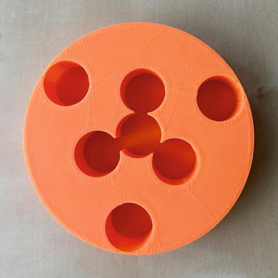
Figure 5-1. The weighted wheel model
Note
We use centimeters and grams or, more generally, the cgs (centimeter-gram-second) unit system in this chapter. First, the natural units of what we are measuring are centimeters and grams, because we are working at the scale of everyday objects. Secondly, because of that, school physics labs (where we expect many of our readers reside) often work in these units for the same reason. However, 3D printers typically measure in millimeters, so you will need to convert centimeters to millimeters if you want to change anything in the model (1 cm = 10 mm).
Use a bit of tape (blue tape of the type used on 3D printer platforms works nicely—see Figure 5-2) to hold pennies in place by wrapping a set of pennies in blue tape. We found that the pennies fell out if we just put blue tape over the holes, and if they rattled a bit it affected the results. We used slugs of 13 pennies per hole for the experiments in this chapter.
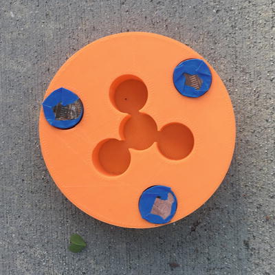
Figure 5-2. The weighted wheel model with pennies in the “outer ring” held with blue tape
Predicted Moments of Inertia for This Model
For the model in Figures 5-1 and 5-2, we will figure out the moment of rotational inertia as follows:
Moment of rotational inertia = Rotational inertia of the wheel + Sum of the rotational inertias of the pennies
Wikipedia ( https://en.wikipedia.org/wiki/Moment_of_inertia ) and other physics references tell us that the moment of inertia of a solid cylinder is (1/2) * M * R 2 . Our model is not a solid cylinder—it is a 3D print with an outer shell, some holes in it, and 10% infill—but for getting general trends, it should be close enough. In this case, the radius R is 50 mm, or 5 cm. With a mass of 46 grams, we get the moment of inertia of the empty wheel without coins as 575 g-cm2.
Simplest Approximation: Pennies as Point Masses
For a first cut at figuring out the center of mass, we will treat the pennies as point masses at their centers. A point mass contributes its mass times the square of its radius from the center of mass of the overall object to the moment of rotational inertia. Later we give suggestions for doing this more accurately, but for now we want to give a rough idea about how to get started.
We used 39 pennies for our experiments, 13 in each of the sets of 3 holes. We measured the mass as 100 grams total. As noted in Chapter 1, some pennies are 3 g and some are 2.5, depending on when they were minted (they were heavier before 1982). We felt that just weighing them was a simple measurement and would allow for wear. All the holes are 20 mm in diameter, just a bit bigger than the 19.5 mm diameter of a penny.
The centers of the outer penny holders are 0.1 cm plus 10 cm in from the outside of the wheel’s 5 cm radius; that works out to 5 – 0.1 – 1 = 3.9 cm. The additional rotational moment of inertia for pennies in the outer ring is thus 100 g * (3.9 cm)2, or 1521 g-cm2. The overall moment of inertia for the empty wheel plus pennies in the outer circle of holes is 575 + 1521 = 2096 g-cm2.
The center of the inner ring of three pennies are halfway between the outer penny holders and the hole at the center of the wheel; that is, 1.95 cm. So, the additional rotational moment of inertia added by pennies in the inner ring is 100 g * (1.95 cm)2, or 380 g-cm2, making the overall moment of inertia for the empty wheel plus pennies on the inner circle of holes 575 + 380 = 955 g-cm2.
Finally, we placed 13 pennies in the central hole; we used 100 / 3 grams as the mass for this. If we are treating the pennies as a point mass at the center, the moment of inertia does not change and is the same as the empty wheel, or 575 g-cm2. The mass, though, is different. Table 5-1 sums up these results.
Table 5-1. Moment of Inertia for Three Cases
Case | Mass (g) | Moment of Inertia (g-cm 2 ) | Moment/mass (cm 2 ) |
|---|---|---|---|
No pennies | 46 | 575 | 12.5 |
Pennies inner ring | 146 | 955 | 6.54 |
Pennies outer ring | 146 | 2096 | 14.3 |
Pennies concentric | 80 | 575 | 7.19 |
Improving the Estimate: Parallel Axis Theorem
The moment of inertia can be calculated about any axis that is fixed with respect to the body itself. So far we have talked about the case of a circular object rotating around its center, but the more general case requires a few more tools.
The point-mass approximation will give a somewhat low value for moment of inertia. The next best approximation would be to treat each stack of pennies as a cylinder of mass 33 grams and radius 0.975 cm. Then we would use the parallel axis theorem which says that the moment of inertia of a distinct part of a bigger object (like our pennies in the cylinder) is equal to its moment of inertia about its own center, added to its mass times the square of the distance from its center of mass to the overall object’s center of mass. In the case here, we would compute this for the inner ring pennies as follows: moment of inertia of a stack of pennies (a cylinder) about its center is equal to (1 / 2) * M * R 2 , where M is the mass of our average stack of pennies or 33 grams, and R is 0.975 cm. Multiplying this out, we get 15.7 g-cm2.
Now to get the moment of inertia of these pennies about the overall body’s center of mass, we use the distance between the two centers of mass times the mass of the stack of pennies to see what the moment of inertia is about the center of the wheel. This distance, as we established earlier, is 3.9 cm.
So, this term adds 33 grams times 3.9 cm squared, or 502 g-cm2 for a total of 15.7 + 502 = 518 g-cm2 per stack. For the three outer pennies plus the wheel itself, we get 3 * 518 + 575 (empty moment of inertia) or a total of 2128 g-cm2, versus the 2096 we got with the point-mass assumption.
Predicting Velocity of the Rolling Wheel
Once we have these numbers, we can predict how fast the wheel should roll downhill. First, we need to compute a formula for the velocity the wheel will have after it rolls down the slope of our experiment, when it will have converted all its potential energy (at the top of the slope) to kinetic and rotational energy. As mentioned in the last section, we know:
Potential energy = Translational energy + Rotational energy
Combining the formulas for each term from the last section gives us:
M * g * h = (1 / 2) * M * v 2 + (1 / 2) * I * v 2 / R 2
Which we can clean up a bit to this:
2 * g * h = v 2 * (1 + I / (M * R 2 ))
Or solving for velocity,
v 2 = 2 * g * h / (1 + I / (M * R 2 ))
where g = 980 cm/s2, R = 5 cm, h = distance * sin(incline angle) , and I = moment of inertia. If we want to get the ratio of the velocities for our current weighted wheel cases, we get the following equation, after dividing out some of the things that we can hold constant from one test to another (like the geometry of the slope, the distance travelled, and so on, assuming here the radius R of the overall body is the same):
v 1 / v 2 = sqrt ((1 + I 2 / ( M 2 * R 2 )) / (1 + I 1 / (M 1 * R 2 )))
The results of plugging in some pairs of values for comparisons are shown in Table 5-2. The moments of inertia vary, but the masses do too. Because this is a dynamic system, the results can be a little surprising. The higher the moment of inertia, the slower the wheel will accelerate, and longer it will take to reach the bottom of the slope. However, the higher moment of inertia in some cases was offset by differences in mass.
Table 5-2. Velocity Ratios Predicted for Some Combinations
Case | Predicted velocity ratio |
|---|---|
No pennies: 39 pennies inner ring | 1 : 1.09 |
No pennies: 39 pennies outer ring | 1 : 0.98 |
39 pennies inner ring : 39 outer ring | 1.12 : 1 |
Results
We tried rolling the wheel on a smooth table with one end raised up a bit, and also outdoors on some sloping concrete. We took our weighted wheel out, rolled it in the configurations in Table 5-1, and measured the distance rolled and the time.
Tip
To get the starting height for our outdoor trial, we used a cell phone bubble-level app (iHandy Level on an iPhone, Multi Clinometer on an Android phone) to measure the angle of the incline. That plus how far the wheel rolled gives us the height difference between the start and end of the test run. Distance rolled times the sine of the slope of the inclined table will give the height difference between the start and stop times.
Rolling it outdoors encountered a variety of problems. The concrete was not very smooth, and had decorative inlaid bricks. The empty wheel stopped very soon after starting and in some cases even rolled backward (in the nominally uphill direction) a bit! However, qualitatively it was interesting to see how much faster the wheel rolled with the pennies on the inside versus the outside.
We would expect the velocity calculated by v 2 = 2 * g * h / (1 + I / (M * R 2 )) to be twice the average velocity over the whole time rolling down the table, because gravity is making it accelerate. We got the average velocity by just dividing the distance the wheel rolled by the time it took to travel it.
The first setup we used was a smooth table 150 cm long, raised 3.14 cm at one end. We let the wheel go on one end and recorded at least three times how long it took each configuration to cross the far end (Figure 5-3). A strategic pillow on a chair and another on the floor at the end is good for catching it so it does not break or dump pennies everywhere when it goes off the edge.
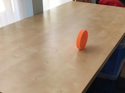
Figure 5-3. The empty wheel heading downhill (to the upper right in the photo) to its pillows
The second setup was outdoors on some gently sloping concrete. We tried to note when the wheel got to 12 feet (366 cm) centered where we were releasing it, trying to repeat the initial release angle as much as possible. We marked our starting spot with a bit of blue tape (Figure 5-4) and you can take advantage, as we did, of decorative markings as start or stop points. It is not a perfect solution because the slope will vary, but the wheels did not roll all that repeatably and other things we tried (see the “Learning Like a Maker” section of this chapter) had other issues. We found an average slope of 3 degrees on the concrete and used that to calculate a height difference of 19.1 cm in 366 cm.
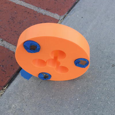
Figure 5-4. Marking the start of a test run on concrete for the wheel with the pennies on the outer ring. Downhill is to the right.
Table 5-3 summarizes these results. We predicted the velocity based on the moment of inertia calculated and the measured heights of the ramps, and then divided by 2 to compare it to the average velocity (just the distance over the time). The empty ring and pennies in center models were only tested indoors. The empty wheel was too easily perturbed by random bumps in the concrete to get any repeatability.
Table 5-3. Measurements
Case | ½ Final v , Predicted | Average Velocity, Measured |
|---|---|---|
Inner ring, outdoors | 86 | 75 |
Outer ring, outdoors | 77 | 66 |
Inner ring, indoors | 35 | 33 |
Outer ring, indoors | 32 | 30 |
13 pennies in center, indoors | 35 | 29 |
Empty ring, indoors | 32 | 28 |
As the physics predicts, higher moment of inertia wheels go more slowly. The measured ratio of the speeds of the wheel with pennies on the inner ring to the outer is 1.14 : 1 outdoors and 1.09 : 1 indoors, bracketing our theoretical ratio of 1.12 : 1 in Table 5-2. There is, of course, a spread in the results because of the many uncertainties, which we note in the following Caution.
Caution
Measuring the angle of a ramp is challenging, and if you choose to try an outdoor patio or playground you will find that slopes vary, even if to the eye they do not. We had many interactions with curious bugs. Concrete is also rough, and friction and breezes are a factor, and sometimes a teeny push was needed to get the wheel rolling. Of course, you need to do this someplace where you can set up safely and without interruption, such as a backyard patio or long sloping walkway. We tried outdoors since our runs on the tilted table were just 5 seconds or so, and timing with a stopwatch app on a phone for sub-second accuracy is possible but challenging. Finally, our assumptions for calculating the moment of inertia of this asymmetrical body (because of the solid bottom) are simplified. In this chapter’s “Project Ideas” section we make some suggestions on how you might improve it. Nonetheless, the trends are correct, and we enjoyed building our intuition as we went.
The Model
The 3D-printable model for the wheel, shown in Listing 5-1, is very simple. It starts with a cylinder and subtracts other cylinders from it. The parameter coin is the diameter of the coins you want to use (plus a bit of margin—we used 20 mm for 19.5 mm diameter pennies, which left room for tape around them).
You can vary the diameter, d, to make a bigger or smaller wheel too. If you change the diameter, holes will remain near the edge, but the ring nearer the center will move outward to be halfway between the center hole and the outer ones. Obviously, you cannot make this a lot smaller than it is now. The radius R we use in previous sections is one-half the diameter d.
The model is pretty straightforward to print. This one is 20 mm high (2 cm), which accommodates 13 pennies. We tried making one with quarter-sized holes and making it thinner, but it was too unstable.
Note
Listing 5-1 uses millimeters (as is conventional in 3D printing), but our calculations elsewhere in this chapter are in centimeters to make the numbers a little easier to handle. Be careful to keep track of that if you change anything.
Listing 5-1. The Weighted Wheel
// A model of a weighted wheel// To demonstrate conservation of angular momentum// file weightedWheel.scad// Rich Cameron, March 2017d = 100; // diameter of disk, in mmh = 20; //height of disk, in mmt = 1; // minimum wall thicknessescoin = 20; // diameter of coin in use, mm$fs = .2;$fa = 2;difference() {cylinder(r = d / 2, h = h);for(i = [0:6]) rotate(120 * i + 60 * ceil(i / 3))translate([ceil(i / 3) * (d - coin - t * 2) / 4, 0, t])cylinder(r = coin / 2, h = h);} // end model
3D printed “cylinders” are made up of small flat surfaces. If you want the wheel to be made up of smaller increments (and thus be rounder and smoother) change the $fs and $fa parameters. In OpenSCAD, the number of faces in the regular polygons used to approximate circles are specified using the special $fs, $fa, and $fn special variables. $fs specifies the minimum size of the facets in mm, with a default of 2 mm. $fa is the minimum angle between facets in degrees, defaulted to 12 degrees. Depending on the size of the object you are printing, one or the other will be important, as follows:
For small, circular 3D printed objects, $fs will keep the number of facets high enough to make the circle look round. A small-enough value for $fs will prevent holes from ending up too much smaller than the specified diameter. This is because the radius of a regular polygon is measured from the center to the vertices, and the apothem (the distance from the center of the polygon to the center of a side) is smaller.
For larger circular objects, a larger $fa value will prevent the number of facets from becoming unnecessarily high, which increases rendering time. $fa needs to be a number that divides evenly into 360 (if it is not, OpenSCAD will round to a number that is).
$fn overrides both of the other special variables and allows the user to specify a specific number of facets. It is usually a bad idea to set $fn globally. Any of these variables can also be specified for each individual object, which provides an easy way to create a regular polygon of $fn sides.
Other Models
Fidget spinner toys are currently popular of late, and there are many on Thingiverse—Rich made one starting from a toy he found at www.thingiverse.com/thing:1802260 . These use radial ball bearings (typically size 608, which are used in skateboards and are thus easy to find) to spin while you play with them (Figure 5-5). This design will even spin on a table (Figure 5-6). If you want to play with something of constant mass and the ability to spin about different arms, you may want to join the fidget spinner craze (though it is a fad that may already be over by the time you read this).
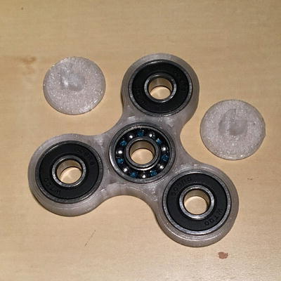
Figure 5-5. Fidget spinner : 3D printed parts plus roller skate bearings
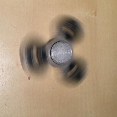
Figure 5-6. Fidget spinner in motion, spinning on a table
Where to Learn More
Moment of inertia is typically covered in a freshman physics class that requires or is taught concurrently with a calculus class. We used Joan’s college textbook, the 1977 edition of Resnick and Halliday’s Physics (Wiley), the most recent version of which seems to be a fifth edition (Wiley, 2001). If you do not want to splash out for and cannot borrow an expensive text, Wikipedia’s article on moment of inertia ( https://en.wikipedia.org/wiki/Moment_of_inertia ) is quite good, as are various related articles (particularly “Rotational Dynamics: Rolling Spheres/Cylinders”) on http://physicslab.org . You might search on “rolling without slipping” to find the types of problems that this model might help you think about. Physics book chapters that discuss topics like this probably have something like rotational dynamics in their titles.
Teaching with These Models
In the United States, material relevant to this chapter is typically taught in a freshman college or AP physics course, where it can benefit from the application of calculus concepts. If you are teaching at the K-12 level, though, we can imagine that some of the experiments we describe in “Project Ideas” could build some intuition under the standards for Forces and Actions ( www.nextgenscience.org/topic-arrangement/hsforces-and-interactions ) even if you did not want to wade into calculating moment of inertia.
If you do have students that are comfortable with the algebra you might have them calculate moment of inertia for various objects they design and predict how fast they will roll, based on the equations in this chapter. You can also talk about experimental error and how much accuracy to expect.
We think it would also be fun to use this model as a starting point for a high school physics or undergrad challenge to have a contest to make the slowest, fastest or longest roll on a nice smooth sloping school pathway, or to most closely hit a particular average or final velocity. To do that you would have to take friction and other forces into account, too.
Projects
If you are trying to build your own intuition or come up with a project to teach others, you could start with the challenge just mentioned. To have that degree of precision, you would need to improve the accuracy of the moment of inertia calculation. Some options are to treat the pennies as cylinders and not point masses, as described in the earlier section that calculates the moment of inertia. You could consider changes to the geometry of the empty cylinder. The references listed under “Where to Learn More” have formulas for moments of inertia of other shapes such as hoops, spheres, and so on.
In addition to improving the calculations, you can improve how you measure time and the inclination of your slope. Using a longer, presumably outdoor slope means you do not have to be quite as good at measuring time, but it is unlikely that you have access to a perfectly sloped and smoothed ramp. You could consider ways to keep the wheel rolling straight without dissipating too much energy in friction.
You can explore ways of measuring the time more accurately. We like the Mythbusters TV show episode setup to measure the speed of a sneeze, which you could adapt if you have the ability to step through video frame by frame ( www.discovery.com/tv-shows/mythbusters/videos/slow-motion-sneezes/ ). The model was designed to fit on a relatively small 3D printer. If you have a bigger printer, you could make a bigger wheel and compare predicted and measured moments of inertia, or try more complex arrangements of coins or other weights.
Summary
This chapter creates a 3D-printable model that allows exploration of the concept of moment of inertia of a rolling cylinder. First we define moment of inertia, as the resistance of a body to rolling motion, analogous the resistance to motion in a straight line caused by the body’s mass. We review how to calculate moment of inertia starting with a simplistic approximation and moving on to slightly better ones. We do some simple experiments using the model and show ways to make both the calculation and the experiment better, at the cost of more complexity. Finally, we end with ways to improve the calculations, as well as projects that could use this chapter’s model as a jumping-off point.