
Chapter 14
Assembling the RepRap Extruder
IN THIS CHAPTER
![]() Looking at thermoplastic extruders
Looking at thermoplastic extruders
![]() Comparing syringe and paste-based extruders
Comparing syringe and paste-based extruders
![]() Setting up for multicolor 3D printing
Setting up for multicolor 3D printing
![]() Explaining extruder operation and upgrades
Explaining extruder operation and upgrades
In this chapter, we show you how to assemble a RepRap extruder and describe how it operates. Here, you find advice on keeping everything working well as you print. We look at alternative materials and explain how you can print with them on your RepRap. Then we show you how to perform multicolor printing and even describe some tricks that make it easier to achieve colorful prints of your own.
Thermoplastic Extrusion
The extruder is one of the most important parts of a 3D printer, so the quality and reliability of parts are critical.
You can make all the parts required for an extruder with basic tools and a lot of time, but it’s well worth paying for well-machined parts that fit smoothly together and won’t leak or melt on you.
All extruders are required to do the same job: Grip the round plastic filament and drive it in a controlled manner to the hot-end, where it’s melted and ejected from the nozzle. The process may sound easy, but when you look at the many parts of an extruder (and, for that matter, of a hot-end), the extruder is the area that causes the most problems for people using home 3D printers.
Filament drive mechanism
Start with the filament drive mechanism, which almost always takes the form of a round bolt or rod with concave teeth that grip around the plastic (see Figure 14-1).
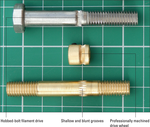
FIGURE 14-1: Typical filament drives used in thermoplastic extruders.
 Filament drive mechanisms can be machined in a variety of ways. Look for even, well-cut drive teeth that grip but don’t strip or grind through your filament. Too-sharp teeth can be as bad as too-blunt teeth.
Filament drives used in thermoplastic extruders perform the same job but are manufactured in various ways. At the top of Figure 14-1 is a traditional hobbed-bolt filament drive, which is the most common type of filament drive; it performs adequately. In the middle is a professionally machined drive wheel, which usually provides the most grip around the filament as it’s pushed into the extruder. This wheel is usually mounted directly on the shaft of the extruder motor or on a gearbox attached to the motor. At the bottom of Figure 14-1 is another machined bar with shallow, blunt grooves; this design won’t grip as firmly as either of the top or middle drives shown in Figure 14-1.
You can assemble an extruder in several ways. In the simplest assembly, the filament drive wheel fits directly on the shaft of the extruder’s stepper motor and drives the filament directly via rotation of the motor shaft. This method provides the lowest torque but requires the fewest other components.
The most basic filament extruder can perform adequately if you have a powerful drive motor and well-machined hot-end to reduce the forces required to push the filament. On the left side of Figure 14-2 is the same professionally machined drive wheel shown in Figure 14-1 (middle image). On the right side of Figure 14-2 is another direct-drive motor, but with only a basic drive cog with a groove for the filament; it won’t have as much grip as the one shown on the left in Figure 14-2. This cog costs little to manufacture but also has the lowest drive performance. A direct-drive motor has no gearing to improve torque, so you should avoid this type if at all possible. Direct-drive extruders do have one advantage: Two of them can be placed close together to provide dual extrusion.
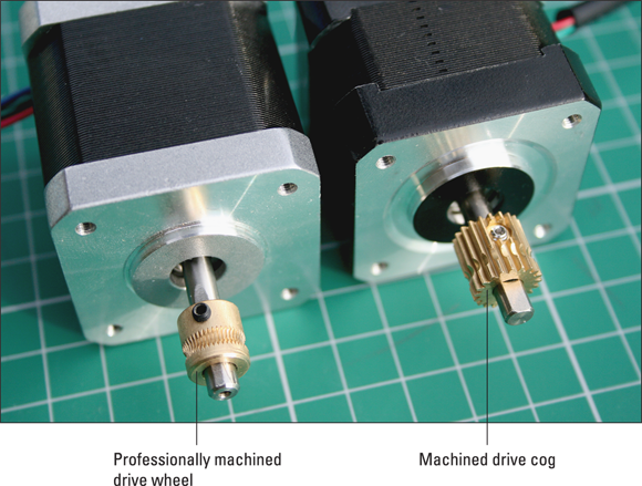
FIGURE 14-2: Two direct-drive filament extruders.
A compact gearbox can be attached to the output of a stepper motor to greatly improve the torque and rotational resolution compared with the direct-drive extruders we discuss earlier in this section (see Figure 14-3). The gearbox can be compact to allow for dual extrusion.
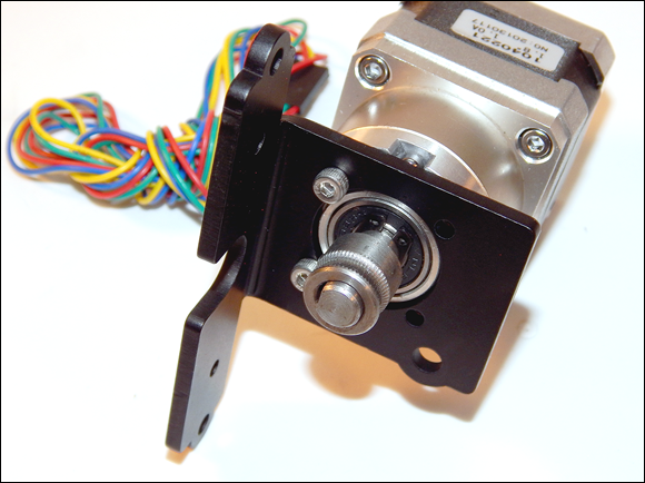
FIGURE 14-3: A professionally made gearbox attaches to the stepper motor, improving the performance of even small motors.
Many enhancements in extruder drive mechanisms have been developed in recent years. One of the most successful is the dual-grip system, shown in Figure 14-4. The advantage of a dual-grip system is that the round filament is gripped and pushed from both sides instead of being pressed flat on the idler side (which usually squashes it onto a metal rotating bearing). More manufacturers are switching to a dual-drive gear system, which increases grip on softer filaments such as ThermoPlastic Urethane (TPU) rubber and helps drive harder or slippery materials faster.
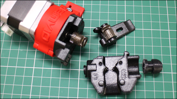
FIGURE 14-4: A Bondtech dual-drive geared extruder mechanism can offer extremely powerful extrusion.
In RepRap 3D printers, it’s still common for the motor to be connected to a series of 3D-printed gears (see Figure 14-5). The gearing allows the motor to turn quickly while the drive mechanism turns slowly, thereby increasing the torque and allowing the filament to be driven with increased force and precision into the hot-end. This arrangement provides fast printing and retraction with less chance of material becoming jammed due to lack of torque.

FIGURE 14-5: The 3D-printed geared extruder has more parts to assemble but can produce greater power and faster printing.
Another common type of extruder is the Bowden, which works on the same principle as the brake-lever cable of a bicycle. A slippery Teflon (PTFE) tube separates the extruder drive motor from the hot-end. This tube allows the driven filament to be constrained and pushed into the hot-end section.
The Bowden extruder is often used in small or lightweight machines because it offers several advantages:
- The design removes the bulk, mass, and weight of the motor from the moving carriage, leaving only the hot-end.
- More hot-ends can be mounted on one 3D printer.
- The design can be ideal for machines with a lightweight head that moves quickly.
A Bowden extruder does have a few disadvantages:
- The design has more parts and complexity compared to a non-Bowden design.
- The printer must perform a longer filament retraction after every print move to minimize oozing due to the pressure and spring that occur when the filament is pushed down the tube.
- The design can be hard to control and tune.
The Bowden extruder shown in Figure 14-6 uses a 1-meter PFTE tube and would be used in a large 3D printer that produces models wider than 500mm.

FIGURE 14-6: A Bowden extruder.
Idler wheel
Any standard single-grip extruder also needs an idler wheel to push the filament into the teeth of the drive wheel. An idler wheel usually is a round bearing pushed by a spring or a rubber bushing. Figure 14-7 shows an idler bearing/wheel fitted to a printed lever; the spring on the left causes the bearing on the right of the image to be pushed into the drive wheel (middle), gripping the filament tightly. With a design using a bearing idler wheel, it must not be overtightened or it will squash rather than grip the filament. If your extruder uses the dual-drive system, in which teeth grip both sides of the filament, the bearing idler wheel is no longer required and the filament is unlikely to be squashed.
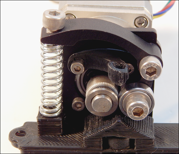
FIGURE 14-7: The idler wheel is essential and must be tightened just enough for the drive wheel to grip the filament.
 Don’t overtighten the idler bearing. If the grip on the filament starts to squash it out of shape, the hot-end’s thermal gets harder to force down, and it may jam. Check how much the drive wheel is biting into the filament. You should see small, regular marks where the teeth bite in, and the filament shouldn’t be crushed.
The hot-end normally is attached to the extruder body with bolts to allow it to be removed if the extruder jams or gets blocked. A finished extruder also requires a heating element on the hot-end, as well as a temperature sensor (see Figure 14-8). This wiring, along with the four motor connections, must go back to the RepRap electronics wiring, which we discuss in Chapter 13.
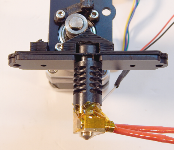
FIGURE 14-8: A wired-up hot-end fitted to the motor and drive assembly. This figure shows a complete thermoplastic extruder with a machined gearbox.
Never try to drive the motor or rotate the gears driving the filament if the hot-end isn’t at the correct temperature. Doing so can cause the extruder to strip and chew up the filament, and you have to clean the teeth on your drive wheel before you can print again.
 A thermoplastic extruder needs to be carefully calibrated to operate well; we discuss all the steps to achieve good calibration in Chapter 15. Extruders are highly active subjects of development for RepRap. Many designs exist (see Figure 14-9), some more specialized than others, offering higher temperature, faster extrusion, or finer detail. Most extruders usually meet the requirements of home 3D printing with thermoplastics.
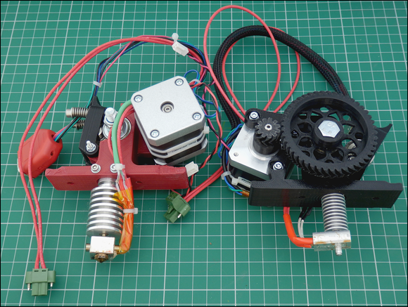
FIGURE 14-9: RepRap extruder designs.
Prusa i3 Extruder and Hot-End Assembly
The final procedure in the example build is assembling the extruder and hot-end — in this case, a modern, compact, geared extruder (refer to Figure 14-8) with a J-head hot-end (refer to Figure 11-17).
We divide the process into five general steps:
- Fitting the filament drive to the motor shaft
- Assembling the extruder idler pressure bearing
- Fitting the J-head hot-end
- Fitting the assembled extruder to the X carriage
- Wiring the hot-end heater and thermistor to RAMPS
The next few sections discuss these steps in detail.
Fitting the filament drive to the motor shaft
Fitting the filament drive to the motor shaft is pretty straightforward. Our stepper motor already has a gearbox fitted to it; this technique results in a small, lightweight, powerful extruder. Other types of extruder assembly use printed gears. A more popular method uses an off-the-shelf gearbox-and-motor assembly to improve the operational life of the printer and increase print quality. All you need to do is fit the drive wheel on the motor gearbox shaft and tighten with an Allen wrench. Figure 14-1, earlier in this chapter, shows an example of this type of drive wheel. Another type is fitted to the geared motor shown in Figure 14-3 earlier in this chapter. All filament drives perform the same job.
You may have to mount a bracket or printed adapter as well, depending on the type of motor you’re using and where you got it. (Refer to Figure 14-3 to see a suitable mounting bracket.)
Assembling the extruder idler pressure bearing
The idler pressure bearing performs the important job of firmly pushing the filament toward the drive wheel so that the rotating motor can force the filament down into the hot-end. See Figure 14-7 earlier in this chapter for an illustration and these general steps for an overview of the assembly process:
- A 3D-printed lever is usually supplied for the idler; to this lever, fit a 623-size bearing (refer to Figure 14-7; the right side of the image shows the small bearing).
- Attach the idler assembly to the motor body, forming a lever.
- Fit a spring between the idler assembly and the mounting bracket to push the idler bearing into the filament drive wheel.
- Attach a small, 3D-printed guide to the motor body with an M3 × 10mm bolt, which helps guide the filament into the gap between the drive wheel and the idler bearing.
Fitting the J-head hot-end
The J-head hot-end most likely comes as a preassembled unit. Fortunately, you can use other compatible hot-ends — such as the Pico from B3 Innovations, the Prusa V2 nozzle, or the V5 from E3D — in the same fitting. See Figure 11-17 in Chapter 11 for examples of such compatible hot-ends, and also an exploded view of an MK5 J-head for reference. Here’s what to look for while fitting the J-head hot-end:
-
The J-head (or compatible) hot-end has a groove mount at the top of the unit. You can slot the J-head hot-end into a slot cut into the metal mounting plate. The metal plate has a standard set of mounting holes so it should be compatible with most 3D printer hot-end carriages.
Make sure that you don’t trap any wires — and be careful with the fine thermistor wiring attached to the J-head body. - Some mounts slot into place; others require M4 × 16mm bolts or M3 × 20mm bolts to lock them in place.
Fitting the assembled extruder to the X carriage
This task usually is a simple one, requiring two M3 or M4 bolts to fit the extruder body on the X carriage of your machine. For the Prusa i3 design, you can download various mounts from the main repository site at
https://github.com/josefprusa/Prusa3-vanilla
or from Thingiverse at
Wiring the extruder to RAMPS
The last part of the build is wiring the extruder motor, hot-end heater, and thermistor sensor to your set of RAMPS electronics. Before you start, check the RAMPS wiring guide at
http://reprap.org/mediawiki/images/6/6d/Rampswire14.svg.
Then follow these general steps:
- Connecting the extruder motor simply a matter of inserting the connector into the electronics control board.
-
Fit the extruder motor to extruder E0 on the RAMPS board.
The extruder motor connection is just another motor drive output so it will look like the X, Y, and Z motor outputs. Make sure you connect to E0 or E1 if you have a 3D printer with dual extruders.
-
Connect the thermistor.
Its two-way header can go in either orientation and connects to T0.
-
Connect the hot-end heater to the D10 screw-terminal connectors in either orientation.
Use ferrules on the wire ends if possible because they make the wire strands less likely to break and help ensure a stronger connection.
Now you can calibrate your machine as described in Chapter 15 and then perform your first 3D print.
Syringe and Paste-Based ExtrusionPaste and clay materials aren’t widely used in RepRap, but they’re among the most straightforward materials in 3D printing. You can print a syringe-based extruder to use on your RepRap 3D printer and start experimenting today.
In the early days of home 3D printing, the Fab@Home project (https://en.wikipedia.org/wiki/Fab%40Home#History) chose to develop open-source printers by using various pastes instead of thermoplastics. RepRap has been a little slow to adopt paste materials for printing, but they can be ideal for some purposes (see Figure 14-10).
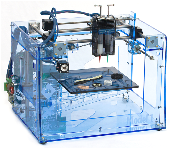
Photo courtesy of Floris Van Breugel
FIGURE 14-10: The open-source Fab@Home 3D printers pioneered paste extrusion.
Richard had a particular interest in syringe-based 3D printing. When trying this process on his own RepRap, he discovered that controlling the material was difficult. Many early attempts at paste extrusion used compressed air to force the material out of the syringe, often without controlling the stop and start of the flow. When the object began printing, it had to keep going until the end, which was fine for printing (say) a flat cookie but didn’t allow much truly 3D printing.
Richard set out to equip his 3D printer with an extruder that could be used and controlled in much the same way as a traditional thermoplastic extruder. After a few models and a flash of inspiration, he ended up with a design for a universal paste extruder (see Figure 14-11). Instead of using compressed air, his design used a normal stepper motor to drive a timing belt that mechanically pulled down a syringe plunger, extruding paste materials onto the build platform layer by layer. This design was released as an open-source project, and before long, people all over the world were using it, developing variations on the design, adapting it for different uses, and fitting it to all manner of machines. That’s how open-source technology is supposed to work.
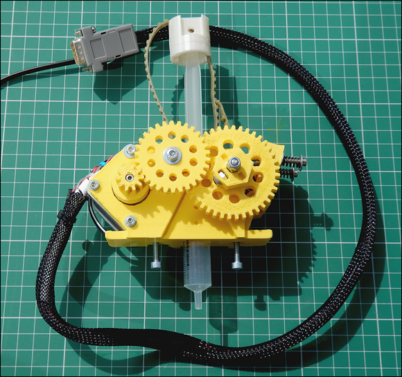
FIGURE 14-11: The universal paste extruder.
The universal paste extruder is easy to use on any RepRap machine because as far as the control electronics know, the stepper motor performs the same job as a thermoplastic extruder. To work this bit of magic, you need only recalibrate the number of steps that the motor requires to extrude a set amount of material. With a paste extruder in place, you can experiment with all sorts of materials (see Figure 14-12). Richard’s favorite materials are clays and ceramics. After all, if you make a mess with them, you can scrape them off your build platform, add a little more water (if required), and try again.
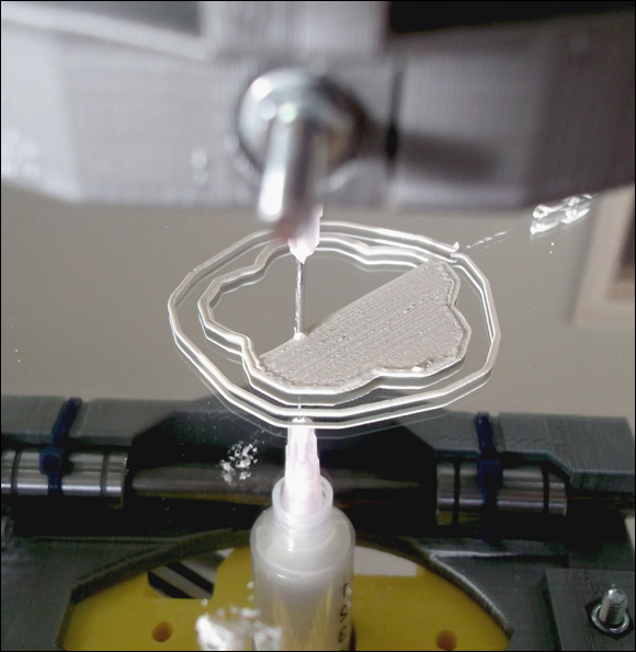
FIGURE 14-12: The universal paste extruder printing porcelain clay on a mirror-glass surface. Note the syringe fitted to the extruder; a fine nozzle layers the clay.
When using paste materials, it’s a good idea to fix a sheet of greaseproof paper or aluminum foil to your platform to keep materials like clay from drying too fast and to make removal easy.
Precious-metal clays and other ceramic materials can be extruded directly into 3D models or jewelry in this way. (Alternatively you would require a plastic 3D print in combination with the lost-wax process to achieve the similar result.) When the parts are dry, some can be fired or finished by hand as needed.
In addition to clay-based materials, you can print with gels, various types of silicon sealants, and many foods (including sugar paste, heated chocolate, marzipan, and frosting) if you can get a smooth-enough paste to form. People have even experimented with various batter mixes that 3D-print directly over a hot frying pan for custom waffles and pancakes (see Figure 14-13).
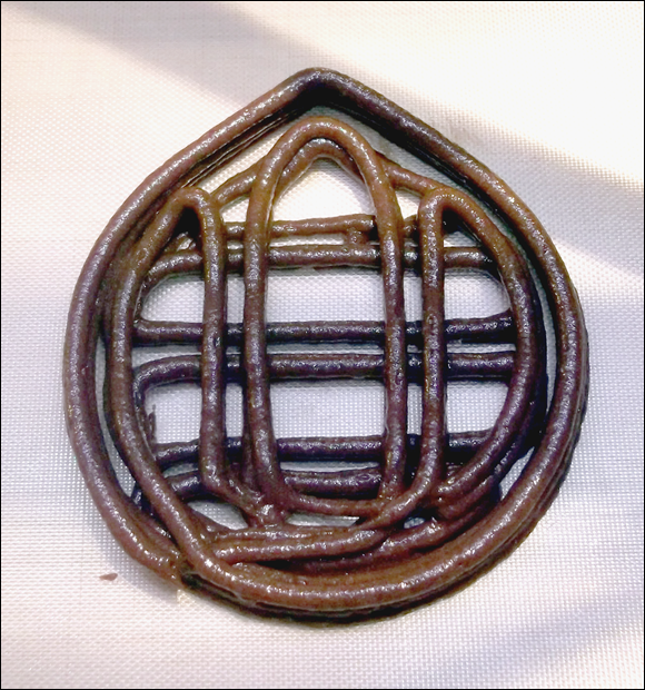
FIGURE 14-13: Printing chocolate muffin mix requires a basic syringe without a needle, which provides a 3mm bead of extrusion.
Pastas and fondants make for great food-based 3D-printing experiments. Masa flour (used to make corn chips) is a perfect food for 3D printing: It sticks to itself, and after it’s extruded onto a baking tray or silicon sheet, you can bake it for the ultimate custom-designed crunchy treat (see Figure 14-14).
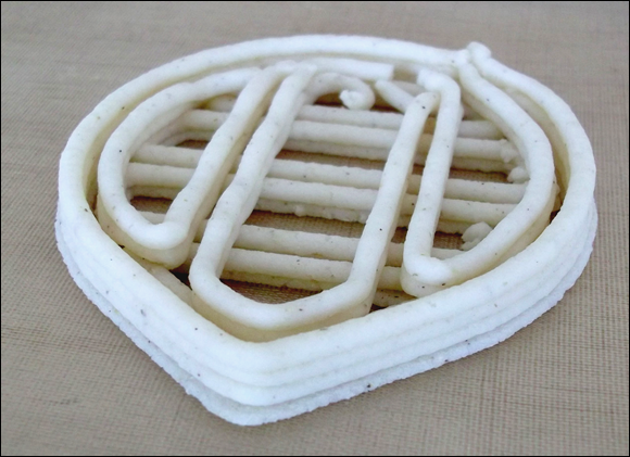
FIGURE 14-14: Masa flour is perfect for 3D printing.
If you want to print your own universal paste extruder, you can get the full build instructions and download the 3D model parts to print at http://richrap.com/?p=60.
Multicolor Print Methods
Another RepRap development goal for home 3D printing is to print objects in many colors and even mix, on demand, the color of your choice from a set five or six master materials. Full-color home 3D printing is still a little way into the future, but you can use several current methods to brighten your 3D-printed objects. This section explores multiextruder printing, color mixing, and achieving impressive results with a single extruder.
Toothpaste effect
In one of the many RepRap experiments conducted at Bath University in the United Kingdom, Myles Corbett and Dr. Adrian Bowyer investigated mixing two colors in a single nozzle. They discovered that plastic materials don’t blend naturally; instead, they produce a “toothpaste effect,” similar to striped toothpaste (see Figure 14-15). Corbett and Bowyer continued to develop the extruder. After trying all sorts of baffles, chambers, and passive methods of achieving a mix, they concluded that only an active method of stirring the melted plastic together inside the hot-end would provide true mixed-color output. They did this — and it worked.
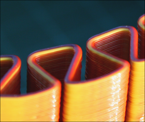
FIGURE 14-15: The toothpaste effect occurs when multiple colored materials are fed into a single hot-end.
If you’d like to read more about this work, you can find an excellent report on color mixing at Bath (more than 50 MB of it) at
www.reprap.org/mediawiki/images/0/05/RepRapColourMixingReport-jmc.pdf.
Three-way color mixing
Richard’s efforts with color and material mixing led to the creation of a three-way extruder that feeds three materials into a single nozzle. He found that each extruder could be controlled and that the toothpaste effect would be interesting, so he decided not to implement an active mixing system. This approach produced unique prints, with different colors appearing on two or three sides of an object (see Figure 14-16).
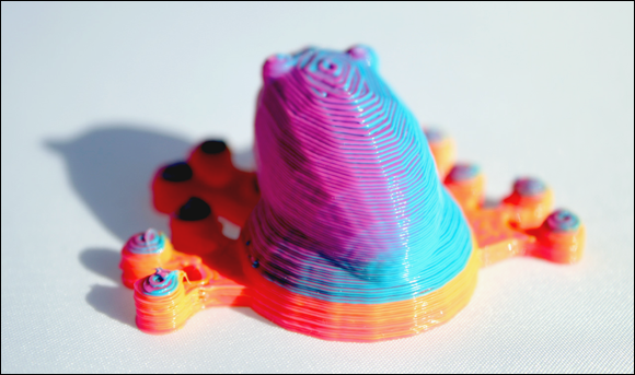
FIGURE 14-16: A three-way blending nozzle combines cyan, magenta, and yellow feeds to produce a psychedelic printed frog that changes color when viewed from different angles.
Further details on this approach to three-way color mixing are available at http://richrap.com/?p=121.
Two-color printing
A much more common way to produce a two-color print is to use two separate extruders and two hot-ends (see Figure 14-17). You can load one color into the first extruder and a different color into the second. For that matter, you could load different types of materials if you find that they’ll print together. The slightly more complex process, which uses thermoplastic, involves these general stages:
- Design two 3D objects that fit together, and load them into your slicing software.
- Specify a different extruder for each printed object, and combine the G-code output into a single G-code file that the printer understands.
- The 3D printer heats both extruders. While it prints the first object with Extruder 1, it drops the second extruder’s temperature enough to keep the plastic from oozing out.
- The printer lowers Extruder 1’s temperature, and Extruder 2 prints the first layer of the second model.
- The printer repeats the process until both models are printed, fused as one object in two colors.
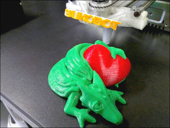
Photo courtesy of Rich Cameron
FIGURE 14-17: A dual-extruder print.
In Figure 14-17, the dragon and heart are separate 3D objects, placed together in the slicing software. One extruder is specified for each object; each extruder is fitted with a different-color filament. (We discuss using multiple extruders in detail in Chapter 15.)
Layer-selective color printing
What if you have only one extruder but want to try some multicolor prints? You can achieve impressive, colorful results on almost any RepRap 3D printer by using a process called layer-selective color printing.
When Richard first made multicolored objects, he designed a simple filament joiner. This approach allowed sections of different filaments to be melted together; when the fused filament line was used in a 3D printer, it made objects with stripes of different colors. You can 3D-print a wide range of useful objects using different colored layers. For example, signs allow a colored background to be printed first and a different color of text to be added on subsequent printed layers. Either joining filament strands together or switching filament color during a 3D print allows production of many separate colors by designing the object’s features with different layer heights and printing different-colored layers on top of each part. The flag shown in Figure 14-18 was designed with the red, white, and blue features at slightly different heights; when one color finished printing, another color printed on top of it. Selecting the parts of specific layers to expose produces a multicolored object.

FIGURE 14-18: Layer-selective color printing with a single extruder involves using different layer heights.
Matthew Bennett’s iPhone cases, shown in Figure 14-19, use the same single-extruder, layer-selective method, but with many more color changes. Clear filaments give the final product more variation.

Photo courtesy of Matthew Bennett
FIGURE 14-19: These iPhone cases are fine examples of layer-selective color printing that uses a single extruder.
Cut-and-follow-on printing
A simpler method doesn’t join the filaments, but uses a two-stage cut-and-follow-on process, as follows:
- Carefully cut the filament close to the extruder while an object is being printed.
- Feed another color manually as the extruder draws down the cut end.
With a little patience and practice, you can use this technique to produce all sorts of interesting color effects.
The only down side is that the filament oozes during printing. With a normal, solid length of filament, the extruder retracts a little after each print move. But the extruder retracts while a section of cut filament isn’t joined to the preceding section; a little filament oozes out of the hot-end. A very fast travel move can compensate for the ooze, but such fast moves weren’t possible in the early days of home printing; in general, filament joining was a better solution.
If you print an entire plate of many parts, and if you can cut and load a new color every 15 minutes or so (or however often you desire), you could end up with an entire set of printed parts in fabulous colors. Figure 14-20 shows the same set of 3D-printer parts we use in the frame construction of the Prusa i3 printer described in Chapter 12. These parts were printed in rainbow colors with a single extruder, using the cut-and-follow-on method for continuous printing.
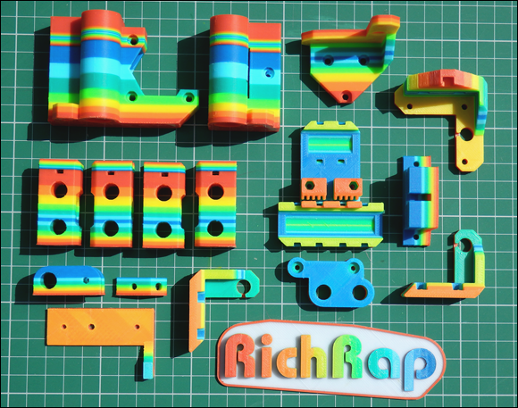
FIGURE 14-20: Continuous multicolor printing via the cut-and-follow-on method.
Extruder Operation and Upgrades
This section is full of tips to keep your extruder and 3D printer happy. Keeping your extruder in tip-top condition is important, because the extruder is the device that takes the most wear and tear in your 3D printer. Follow this advice to make your 3D printing go smoothly, prevent failed prints, and keep your new 3D printer in action:
-
Check the accuracy of your software and firmware. Always make sure that the temperatures reported by your firmware and software are accurate. This check can resolve a lot of common problems and extend the life of your 3D printer.
You can check the temperature in several ways. One of the best methods is to insert a thermocouple probe into the hot-end nozzle. Or invest in a noncontact digital laser temperature sensor, which sells for around $30 (see Figure 14-21). To use it, point the laser at the place you want to measure. This device is good for checking the temperature of the heated print bed, motors, and drive electronics.
-
Verify the temperature of your cold-end. It’s a great idea to check how hot the cold-end (thermal barrier) is getting on your hot-end. As we discuss in Chapter 11, the cold-end’s temperature needs to stay below the glass-transition temperature of the material you’re printing. This limit is most critical for printing polylactic acid (PLA) materials, so check your extruder when it has been turned on and printing for 20 minutes or so. If the extruder heats up more than 50 degrees C, consider adding a cooling fan. Make sure that this fan points across the cold-end part of the extruder, not toward the hot-end or the object being printed.
Some 3D-printer kits come with a fan to cool the cold-end of the extruder — usually, a very good idea. A fan isn’t always necessary, but having your incoming filament go quickly from cool to melting temperature is much better than trying to push a plug of heated, semisoft, rubberlike material into your extruder nozzle. - Keep your filament free of fluff. Add a fluff-capturing device to your 3D printer, because dust and fluff on the filament going into your hot-end can clog it and eventually jam the nozzle. Such gunk is very hard to clear out. A piece of sponge, secured around the filament with a zip tie, catches fluff and stops it from entering your extruder (see Figure 14-22).
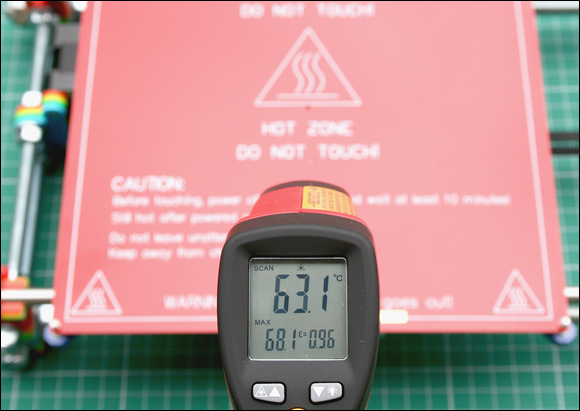
FIGURE 14-21: Use a noncontact laser temperature sensor to make sure that the parts of your 3D printer are running at the correct temperatures.
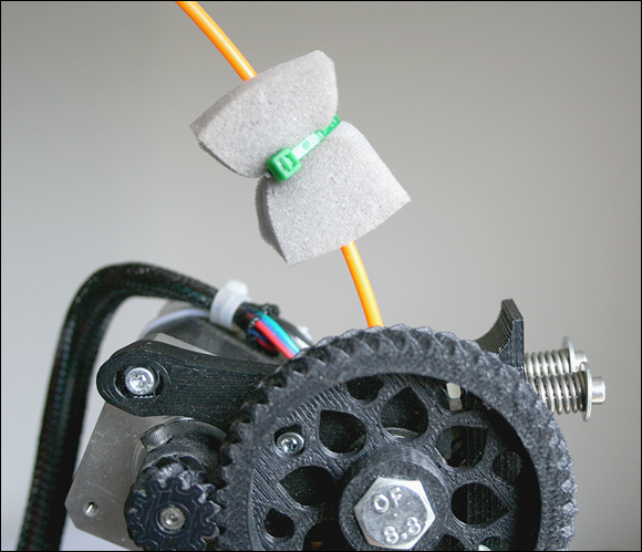
FIGURE 14-22: A piece of dry sponge keeps fluff, grease, and dust from entering (and jamming) the tiny nozzle of your hot-end.
Fixing a blocked hot-end or extruder
When your hot-end gets blocked or your extruder’s filament drive fails, the warning signs are usually obvious. The stream of plastic starts to lessen and then stops; the printer keeps trying to print but extrudes layer after layer of nothing.
The first things to do are stop the printer and ensure that the heater block on the hot-end is still at the expected temperature. (Ideally, for maximum safety, you should use a noncontact laser temperature sensor, as discussed in “Extruder Operation and Upgrades” earlier in this chapter.) If the heater temperature is significantly below 160 degrees C, the heater used in the hot-end or temperature sensor may have failed, or the wiring or electronics controlling the heaters may have developed a problem.
Unfortunately, wires commonly break — and insulation wears away — on a home 3D printer due to the constant movement of the machine. Wiring should always have plenty of room to move around gently, with enough slack — not tightly bent or yanked back and forth as the machine moves. Using silicon-coated wire can help, especially if it has extra resistance to heat. Increasingly, new machines use gently curved ribbon cable — a ribbon of many parallel wires instead of a single thick wire — which tends to alleviate cable strain and damage.
If your heater block is jammed but is at the expected temperature, follow these general steps to clear the jam:
- Keep the heater block turned on.
-
Make sure that the filament drive isn’t blocked and that the filament isn’t buckled or wrapped around the extruder drive wheel.
If you think you may have a blockage, follow the steps here. If you have buckled filament wrapped around the drive wheel, first remove the buckled filament, and then follow the next steps to check if the cause of the buckle was a blockage.
-
Release the idler bearing, and gently pull out the filament.
A filament rarely gets so jammed that it can’t be pulled out while the hot-end is at temperature. More commonly, the removed filament shows signs of being overly compressed — a little fatter where it melted inside the hot-end. Usually, pulling out the melted filament removes contaminants from the hot-end nozzle.
-
Cut off the melted filament end, and push it into the hot-end.
If you can push down, and material is extruded from the nozzle, you’ve cleared the blockage. Otherwise, proceed to Step 5.
-
If you can’t get the material to extrude, allow the end of the material to melt, and pull it out again.
Repeating this step several times should clear most blockages. If not, proceed to Step 6.
-
If you still have a blockage, do either of the following things (extremely carefully):
- Push a pin or small drill bit into the nozzle end while pulling out the melted filament.
- Allow the hot-end to cool, and when it’s cool, use a chemical solvent (such as acetone) to dissolve any buildup.
Before using any chemical cleaner, check with the supplier, and mention the type of material that you were using in the hot-end when the jam occurred.
You may be starting to think that having a few extruders is a good idea — and usually, it is. In the event of a blockage, a backup extruder can get you printing again while you repair. Another reason for having a choice of extruders is that your machine becomes much more capable of printing different types of objects, which can widen your selection of available printing materials.
Acquiring an assortment of extruders
For thermoplastic printing, it’s a good idea to have two or more extruders of the same type, but with different nozzle sizes and maybe a choice of 3mm or 1.75mm filament. Some materials — especially experimental materials — tend to come in 3mm and less often in 1.75mm. Depending on the manufacturer, 3mm filament may cost less than 1.75mm filament.
Having a choice of nozzle sizes is great if you intend to print parts of varying quality. Although you can always print with a small nozzle, the print job may take a lot longer for certain parts. Using a bigger nozzle can be handy if you want to create rough drafts of your models or intend to finish the resulting object with paints or fillers.
A good all-around nozzle size is 0.4mm, which allows for fine detail and a reasonable print time for most parts. You can also select layer heights of 0.3mm or lower.
This isn’t to say that a big nozzle can’t provide high quality. You can select very low layer heights if you’re using a big nozzle, which makes the vertical quality of a print almost identical to what you’d get with a small nozzle, though some fine horizontal details may be lost if the model has many sharp corners and features. Think of a 3D-printing nozzle as being similar to a paintbrush. You can use a small brush or nozzle for finer details and sharper edges; a big brush or nozzle “paints” faster but can’t resolve intricate details clearly.
A typical large nozzle for a home 3D printer is 0.6mm or 0.8mm. A 0.6mm nozzle allows you to print layers of 0.5mm or lower and usually gives you a much faster print time than smaller nozzles. Some large RepRap printers use 1.2mm nozzles to produce models a meter (or more) tall or wide in size.
Don’t set a layer height that exceeds the size of the nozzle. Keep the layer smaller than the nozzle to ensure good bonding of plastic layer on layer.
 You can try using as small a nozzle as your machine mechanics allow. Keep in mind, however, that normal minimum layer heights are around 0.1mm (100 microns) — about the thickness of a sheet of office paper. Most RepRap machines allow layers of 0.05mm (50 microns) and even smaller, but printing time increases dramatically, and the extra quality is hard to distinguish. Common layer heights are 0.2mm or 0.25mm, which produce a highly presentable surface. As you become more accustomed to 3D printing and tune your printer to run faster, you’ll find pleasing resolution at layer heights around 0.15mm or 0.1mm.
If you decide to keep more than one extruder available for your 3D printer, you don’t need to fit all the extruders on your machine at the same time. In many situations, having a quick-fit mechanism that allows you to change extruders easily makes sense.
Richard struggled with multiple extruders when some of the first RepRap machines were being developed. At the time, all extruders were mounted permanently on the moving X-axis carriage with nuts and bolts. Changing extruders was time-consuming and tricky, and users couldn’t even think about having more than one type of extruder.
Richard developed a quick-fit carriage and various extruder bases for the most common hot-ends and paste extruders. The idea was to allow experimentation and make extruders easy to change and lock into place on RepRap printers (see Figure 14-23).

FIGURE 14-23: A replacement X carriage compatible with many RepRap 3D printers. The yellow lever at left allows the quick fitting and removal of extruders.
Cooling extruders with fans
Here’s a final tip for using 3D printing extruders: Use fans. In “Extruder Operation and Upgrades” earlier in this chapter, we discuss using a small fan to keep the cold-end insulator of your hot-end below the glass-transition point of your plastic. When you start experimenting with printing ultratiny objects with fine details or printing objects at great speed, you quickly discover an interesting problem in 3D-printing thermoplastic materials: controlling layer temperature.
If you print tiny parts that have little layer surface area or turn out objects at such high speeds that each layer is completed in a matter of seconds, the layer of plastic just laid down doesn’t have time to cool, so it’s still a little molten when the next layer is laid down. With the radiated heat from the nozzle and more hot plastic being extruded, the model can end up being a messy blob instead of the object you intended. You can slow the speed, but you may not resolve the problem; you shouldn’t have to wait even longer to print an object anyway. In this situation, a controlled cooling fan can make a massive difference.
The cooling fan is usually around 80mm wide and is controlled by the electronics. In your Slic3r-generated G-code, you can specify how fast a cooling fan runs and when the fan turns on and off. When your printer has a cooling fan fitted, Slic3r can run the print at full speed, even when printing fine details of a model. When your printer doesn’t have a fan, Slic3r has to instruct the G-code to slow to allow natural cooling of the plastic before adding more. As you can imagine, fine structures can be tricky to print without a cooling fan.
We discuss setting up the fan with Slic3r in Chapter 15. In this section, we point out that a fan permits bridging of extruded material — an essential part of many 3D-printed objects. Bridging occurs when a model has to span a gap, essentially making a bridge in thin air. If you extrude plastic with nothing below it, the extruded material naturally sags and sometimes breaks. Although you can bridge filament without using a fan, you usually have some strings of snapped extruded filament hanging down, as well as a little sagging. When you use a fan to cool the plastic as it’s extruded, you can make a tight bridge and get smart-looking results (see Figure 14-24).
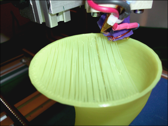
FIGURE 14-24: Bridging a filament. With good cooling and a few alternating layers, the spanned first layer becomes a solid surface that can be printed on after a second bridging layer in the opposite direction.
Mount the fan so that it cools the top layer of the part being printed. If you cool the heated bed, your part will pop off in the middle of the print. If you accidentally cool the hot-end, your extruder may jam. It’s quite common for a cooling fan to have a 3D-printed duct that directs a stream of air across the printed object while it prints, to minimize unwanted cooling of the heated bed and hot-end (see Figure 14-25).

FIGURE 14-25: A printed duct cools the part being printed and doesn’t accidentally cool the hot-end heater.
In almost all cases, it’s not advisable to use a cooling fan when printing acrylonitrile butadiene styrene (ABS) material. The fan may cool the edges of the material too fast and cause them to curl; the next layer may be worse. Eventually, the part can be so deformed and warped that the print head may knock it off the build platform. By contrast, PLA likes a fan.