
Chapter 15
Identifying Software and Calibrating Your 3D Printer
IN THIS CHAPTER
![]() Locating 3D design software and models
Locating 3D design software and models
![]() Preparing, slicing, and selecting settings for models
Preparing, slicing, and selecting settings for models
![]() Calibrating your 3D-printing machine
Calibrating your 3D-printing machine
![]() Creating your first 3D-printed objects
Creating your first 3D-printed objects
This chapter covers the final phase of RepRap machine setup: processing and calibrating 3D models. In this chapter, we discuss the best ways to print models, and look at various sources of 3D models and common 3D-modeling packages. We go into detail about on preparing the model files and producing output G-code (with Slic3r) that you can use with your RepRap 3D printer. Before getting into the nuances of printing parts, we show you how to make sure that your machine is calibrated and ready to print your first object. Finally, we look at some common types of 3D objects and how to use specific settings to achieve the best 3D-printed results.
Finding 3D Design Software and Models
The entire 3D-printing process starts with a 3D model. In this section, we take a look at some of the steps you need to understand to achieve successful 3D printing of models. It's not a click-and-print process. You need to have the correct format of model and choose settings that will process that model within the limitations of the 3D-printing process.
Objects designed for home 3D printing are ready-made models. Usually, the designers of these objects have home 3D printing in mind, expecting that their models will be 3D-printed before any modeling process starts. After all, if you get a taste of the results, you have a clearer goal when you start making your own models.
The promise of home 3D printing doesn’t mean that you can print anything and everything. This practical limitation can frustrate users who expect to jump right in and start printing high-quality parts for product development or model-making, or as substitutes for products crafted by hand or manufactured traditionally.
In fact, 3D printers are good at producing objects that can’t be made by other manufacturing techniques. Figure 15-1 shows two such examples. Most users, however, don’t need to create such complex models — at least, not for first projects. Most home users of 3D printing face the more standard problem of simply getting what they need out of a 3D printer.
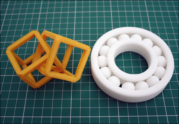
FIGURE 15-1: Two 3D-printed objects that would be almost impossible to produce on injection-molding machines.
As an example, if you wanted to print a model of a person for a scale-model railroad, you might want that person to be in a seated position with arms stretched out (see Figure 15-2). Software packages such as Smith Micro’s Poser (http://my.smithmicro.com/poser-3d-animation-software.html) and Trimble’s SketchUp (https://www.sketchup.com) make this sort of modeling easy to do. A 3D-printing bureau that uses a professional selective laser sintering (SLS) 3D printer, such a professional operation would have no problem printing this model. Trying to print it yourself on a home 3D printer, however — especially as an ambitious early project — can be a real challenge.
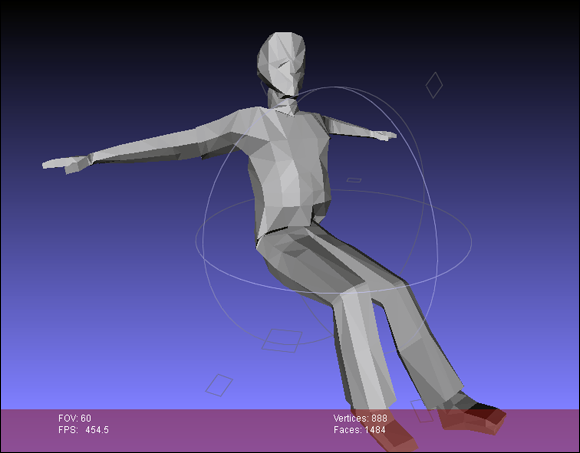
FIGURE 15-2: A posed person is a challenge to print on a home 3D printer; the model has overhangs where the printed material would lack support.
The main difficulty for fused filament fabrication (FFF) printers such as RepRap is that they can’t extrude into free air; the object must be supported while the printing is going on. Each new layer needs a supporting layer to build on. In printing a model of a seated person, then, the feet and lower legs print just fine, but the 90-degree overhang of the upper legs and the outstretched arms present a problem: The extruded filament has nothing to attach to. With nowhere to go, the filament collapses into a mess of extruded spaghetti.
A professional SLS 3D printer works differently: It builds objects by using fine nylon powder. A laser melts the nylon layer and fuses the shape of the object; then another complete layer of fine powder is spread over the build surface, and the process repeats. The main difference is that all that spare unfused powder provides support for the fused parts as they build; the parts that eventually extend from the model into free air can be built with support from the unfused powder and stay in place while being printed. When the model cools and the excess powder is brushed off, the model is complete. Models printed this way can be almost any shape and complexity. That process isn’t possible with home 3D printers — at least, not yet.
To help with this problem, you can use a support structure that builds a fine column of material from the base of the bed (or from the printed part itself) to support any overhanging features. The Slic3r software (discussed in the next section) can detect where to add support. You can even use a second extruder to put a different support material in the build.
 Normally, home 3D printers use the same material for the model as for the support material. All the extra material has to be snapped off, and the model cleaned up a little, when the print is complete (see Figure 15-3). Slic3r model processing software can add support material automatically wherever it’s required. This approach works well. Remember, though, that the support material is temporary and must be cut away when the print is finished. This cutting can leave marks and scarring. If the printed parts are intricate, removing the support by hand can be difficult (see Figure 15-4 and Figure 15-5). Using a second extruder to provide a more workable support material — say, a thermoplastic such as polyvinyl alcohol (PVA) — allows you to trim the object by submerging it in warm water. The PVA dissolves, revealing the finished model. Dissolvable support material will probably be a commonplace feature of future home 3D printers.
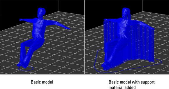
FIGURE 15-3: The unprintable model (left) and the same model with breakaway support material (right).
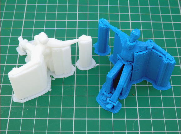
FIGURE 15-4: Take care when removing the support material; small, fragile parts can be damaged or snapped off.
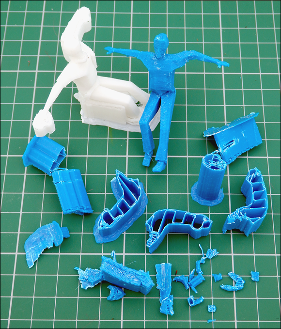
FIGURE 15-5: This support structure is mostly hollow and easily removable with needle-nose pliers. Further cleanup may require a sharp blade or small file.
3D printers like the BCN3D Sigma (see Figure 15-6) use a dual X-carriage system that allows two different materials to be printed with independent extrusion and movement systems. A primary material can be loaded and used on the left extrusion system while the right system is parked. When a support structure is required, the left head can park, and the right head takes over. This system allows much more freedom in model creation. Desktop 3D printers are not quite at the point of being able to print “anything” — for example, very fine details in jewelry where even support material can’t “support” the fine structures using the thermoplastic materials we have available — but the technology is moving in the right direction.
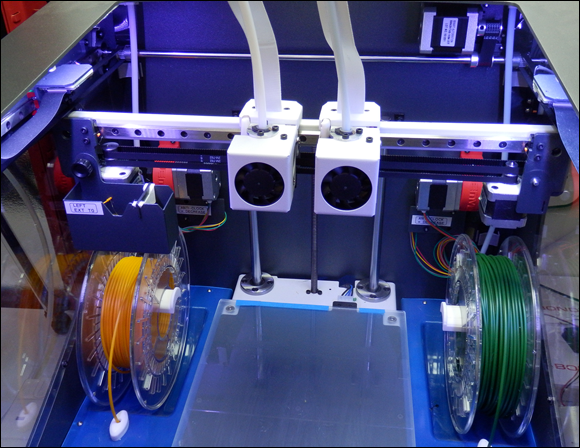
FIGURE 15-6: The dual independent carriages of the BCN3D Sigma allow you to use two different materials without one oozing on the other or getting in the way of printing.
You can get around (or minimize) the use of support material by rotating the model in Netfabb before printing. (See Chapter 11 for a Netfabb overview.) If you rotate a model of a seated person so that the back and arms are on the base of the print surface, for example, you may not have to use support material at all (see Figure 15-7).
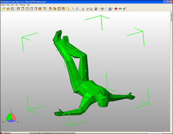
FIGURE 15-7: Rotating a model in Netfabb to make printing easier.
No wonder 3D-printing sites often provide models designed for home 3D printing. A model of a person would most likely be posed standing straight up, with hands by the sides or in contact with the upper legs. In either case, no extra support material is needed, so the model can be printed easily on a home 3D printer. Most home users would struggle to print models in more complicated poses, due to the way that 3D printers build up models layer by layer. For this reason, if you require a model of a seated person, you may have to use support material (refer to Figures 15-4 and 15-5).
Another way to avoid adding support material is to divide a complex model into two or more parts, each of which requires little or no support material. After printing these parts, you can join them with glue.
You may be better off dividing complicated objects into subassemblies. All parts are printed flat on the build plate and later assembled into complex, functioning objects. The planetary gearbox shown in Figure 15-8 is a real challenge — even for a professional-grade 3D printer — to build as one complete, functioning object with no manual assembly required. Stay tuned, though; this goal is getting closer all the time.
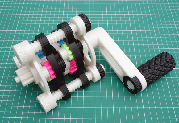
FIGURE 15-8: A multistage planetary gearbox. Home 3D printers can make all the parts, but some assembly is still required.
Using design software
Many software packages for designing 3D models are available. Many are open-source or free and include export options that support the STL model format used by RepRap 3D printers.
One popular option for RepRap developers is OpenSCAD (www.openscad.org), shown in Figure 15-9. This free and open-source 3D modeling program is built and maintained by individuals. OpenSCAD has an ever-expanding and comprehensive array of examples, libraries, and resources. It allows parametric modeling, which allows you to change almost any of a design’s dimensions, shapes, or features by altering the appropriate parameters (numbers or formula). With parametric modeling, you can specify a generic model of a shoe insole then enter specific details about your foot, size, shape, and the desired level of comfort (flexibility in the material). The parametric software modifies and produces a new custom-fitted 3D model based on the settings you entered. The down side of this software is that it’s complex. Unless you’re familiar with programming and have a good mathematical grasp of geometric 3D space, you may struggle to work with this software.
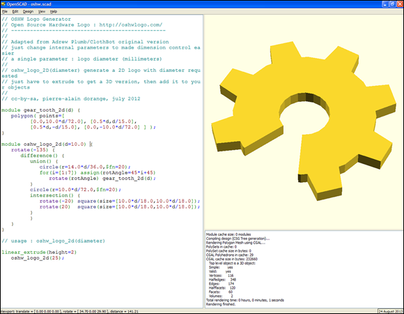
FIGURE 15-9: Because of its parametric nature, OpenSCAD can accommodate many options with a small change of code.
Another popular package is SketchUp Make. This visual modeling tool is a good program to use to experiment with your own designs or alter existing 3D models. Find it at www.sketchup.com/download/all.
You can use almost any type of 3D-modeling program. Many programs now exist as cloud-based applications that produce customized 3D models (or allow you to make those models easily).
Many more consumer-level software products are specifically designed for 3D printing. All provide easy-to-use applications for modeling objects designed for home, hobby, or business 3D printing. Examples include
- Tinkercad (
www.tinkercad.com) - Meshmixer (
www.meshmixer.com) - Autodesk Fusion 360 (
http://www.autodesk.com/products/fusion-360/overview) - Solidworks (
www.solidworks.co.uk/) - Rhinoceros (
www.rhino3d.co.uk/) - Autodesk Remake (
http://remake.autodesk.com/about)
The output format you require for a 3D printer is Stereo Lithography (STL). This file format is usually available as a standard export option, although some packages require a plug-in. If you’ve already obtained an STL model file from an object repository or as an export file from your 3D modeling program, check the model to make sure that it works with your software, as discussed in the next section, “Verifying models with Netfabb.”
Verifying models with Netfabb
If you have an STL model file, you have to verify the model before you can print it. Software programs and slicing tools for 3D printing see all 3D models, including solids, as a series of triangles that join to create a hollow mesh surface. The triangles in your model must not intersect other triangles; if they do, they create an invalid mesh that causes problems if you try to 3D-print the model.
It’s a good idea to verify that your model export or download is a valid mesh. A valid mesh for 3D printing is one that has a complete surface, and it’s also called manifold or watertight. All STL 3D models for 3D printing are exported as a hollow shell, think of them like a balloon. The model, like a balloon, has both an outer and an inner surface (skin) defined by many connected triangles to form the surface, with nothing inside the skin. If you had a hole in the balloon or 3D model the structure would not be viable. A 3D model can have missing triangles that produces holes in the mesh surface and cause it to become invalid. Triangles of a model can also be accidentally flipped so sections of the inner and outer surfaces become reversed. One of the most common modeling and export errors occurs with triangles that are not joined as a surface, but intersect each other, causing great confusion when trying to process for 3D printing.
Finally you also need to have the 3D model in the correct orientation for 3D printing, and check that its size is what you expect and require. Netfabb Basic works well for this sort of checking because it highlights problems with exclamation marks and shows the orientation onscreen, allowing you to repair, scale, and reorient the model as needed for export and 3D printing (see Figure 15-10).
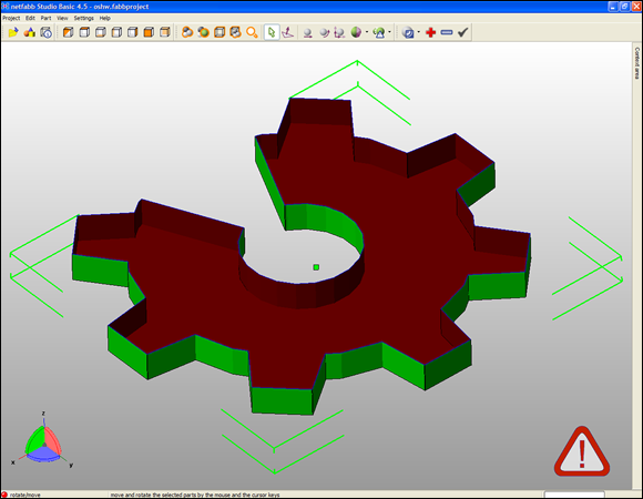
FIGURE 15-10: Netfabb highlights problems in your model with exclamation marks.
When mesh errors are present, you can use Netfabb to make repairs. After rotating and scaling the model as needed, click the + button to attempt a repair. Then select Standard Repair and click Apply Repair to obtain a new model that you can export for 3D printing (see Figure 15-11).
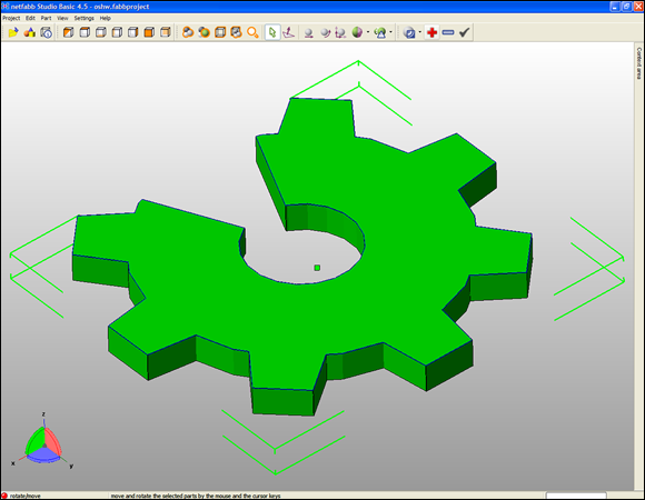
FIGURE 15-11: Netfabb detected that this model isn’t solid. After repair, the solid model can be 3D-printed.
Working with Slic3r
Slic3r is a print-slicing program (also mentioned in Chapter 11) that processes 3D models for printing. You can download the Slic3r software for PC, Mac, and Linux at http://slic3r.org. Before you work with the material in this chapter, we recommend that you download and install Slic3r on your computer.
Configuring Slic3r
After you successfully install Slic3r, you can configure it. Slic3r has to know several key settings for your particular 3D printer. You enter these settings in a configuration wizard that appears when you first start Slic3r.
 Don’t worry — you can change all these settings later if you need to. For now, enter as many of the specified details you can. You can save different configurations later. This arrangement is useful when you’re running several machines, testing upgrades, or trying different material types.
To configure Slic3r, follow these steps:
-
In the Configuration wizard, select the style of G-code to use with the firmware you’ll be running on your RepRap 3D printer (see Figure 15-12).
Usually, this G-code is RepRap (Marlin/Sprinter) as that's the most common type of firmware and tends to also be most compatible with other variants, so it's a good choice.
-
Enter the size of your printer’s build bed.
For a RepRap that uses a Prusa-style heated bed of printed circuit board (PCB) material, enter 200mm x 200mm. A delta printer has a rounder build area, which you have to consider when you’re printing objects, but you can enter the size as X and Y coordinates.
-
Enter the size of the output nozzle on your 3D printer’s hot-end.
Common sizes are 0.5mm, 0.4mm, and 0.35mm. Slic3r uses this information to calculate the gap between the extruder nozzle and part surface necessary to extrude each layer so that each layer bonds securely to the one beneath it. This setting serves as a guide for Slic3r; tuning the width and height of the extrusion path is a separate, independent part of the calibration process.
The extruded width of the output also depends on many tiny aspects of the hot-end design. Commonly, some die swell — when molten plastic material expands under pressure on exiting the tiny nozzle; the output filament expands from the nozzle as it exits. Print calibration, then, is important to prevent extruded plastic layers from extruding too close together or too far apart, which prevents your 3D models from looking right and functioning correctly. -
Enter the filament diameter.
Be sure to measure the diameter of your filament, get the best average, and enter that result as the filament diameter for Slic3r — preferably after you ponder the cautionary sidebar “Check your filament carefully.”
 Newcomers to 3D printing who discover a lack of material or overextrusion on their printed objects often change the filament diameter setting to adjust the volume of material. This method can work, but as a rule, we don’t recommend it. Inaccurate extrusion often masks a bigger problem with extruder calibration or machine setup. These problems manifest themselves as poor print quality, overextrusion of material, and an incorrect fit for holes and apertures. Any fudge- actor applied to settings leads to inaccurate calculation of print time and material being used. Use an accurate measurement for filament diameter, and never adjust this number to tweak the volume of plastic being extruded.
 -
Continue with the Slic3r configuration wizard, setting up your extrusion temperatures and selecting heated bed temperature settings.
The extrusion temperature of a thermoplastic in 3D printing has to be high enough to allow your extruder to push material consistently into the hot-end without stalling, but not so high that the plastic gets runny and overheated, which causes it to break down and smoke. You will need to set up the extrusion temperatures for common types of plastic you are likely to extrude in your 3D printer. For PLA, the temperature is around 200 degrees C; for acrylonitrile butadiene styrene (ABS), the temperature is around 240 degrees C.
Usually, you need to increase printing temperatures when you print significantly faster than normal. More energy needs to be transferred faster into the faster melting plastic flow. Or when printing a tiny, detailed object slowly, you often need to reduce the print temperature to limit oozing of the plastic (too much thermal energy produces oozing). For more about extrusion temperature, see “Tuning your hot-end temperature control” later in this chapter. -
If your RepRap 3D printer has a heated bed, enter a temperature value for the material that you intend to print.
Again, don’t worry if you plan to print different materials; you can set up multiple configurations in Slic3r later. As a guide, use 60 degrees C for PLA and 110 degrees C for ABS. If you want to print without using a heated bed, leave this value set to 0.
Almost every RepRap 3D printer needs to be tuned for specific printing temperatures. It’s fine to use other people’s suggestions as a guide, but exact locations of the temperature sensor and small variations in the electronics and firmware setup may give you a very different reading.
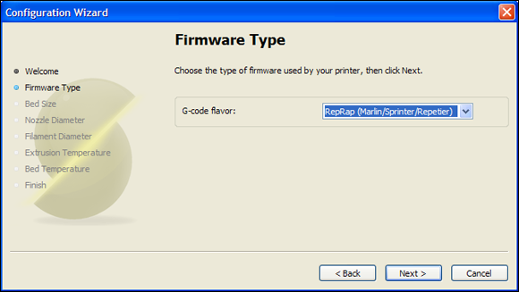
FIGURE 15-12: Choosing the G-code for your firmware.
Processing models with Slic3r
After Slic3r is installed and configured, you can use it to process your valid model. Slic3r processes your model to create an output G-code file, ready for printing.
Note: The example in this section runs Slic3r in Simple mode. When you become more familiar with your 3D printer and its capabilities, you can switch to Expert mode, which offers many more options.
Slic3r is continually modified and upgraded, so use the following steps as a general guide to preparing an object for 3D printing and outputting the G-code file. Expect changes in the user interface, options, and degree to which the program detects the best settings for objects.
Follow these general steps to process your valid model:
-
Position the model for printing by loading it into Slic3r.
When you have a valid model correctly oriented and scaled, load it into Slic3r by dropping the file into the Plater window, which provides a scale view looking down on the outline of your model (see Figure 15-13). You can load and move other objects on the virtual build plate if necessary.
-
On the Print Settings tab, select suitable print settings for your model.
The Print Settings tab (see Figure 15-14) provides options that tell Slic3r how you want the model to be printed, and at what speed and quality:
- Layer Height: This setting determines how finely your model is vertically sliced. The finer the layers, the better your finished print looks, but the longer it takes to print. A typical layer height is 0.25mm for a 0.4mm or 0.5mm nozzle.
- Perimeters (Minimum): This setting is the number of times the extruder draws the outer surface of a layer before doing the infill. Normally, you use at least two perimeters to ensure a solid, good-looking object.
-
Solid Layers: The Top and Bottom settings ensure that the top and bottom of an object are solid. For most models, it’s good to start with three top and bottom layers.
If you select zero top layers and no infill, your model is printed as an outer shell with as many perimeters as you selected — ideal for printing pots, vases, and other types of hollow objects. We discuss other options for printing pots in the section “Printing vases, pots, and cups” later in the chapter. -
Fill Density: This setting is as a percentage, so a setting of 0.25 creates a 25 percent level of plastic infill for an object. A level of 0.3 (30 percent) is a good setting for most functional parts.
The objects you print almost never require an infill of 100 percent. You don’t need to use more plastic to achieve only a slight gain in strength. Normally, display models are printed with less than 15 percent infill. Functional parts such as those needed to build a 3D printer usually require infill of 25 percent to 50 percent. - Fill Pattern: This setting allows you to specify how the interior of an object is filled. The most common fill-pattern settings are Rectilinear and Honeycomb; Concentric is often used for round parts or for vases, pots, and so on. For mechanical parts, Honeycomb is the strongest setting, but it’s slightly slower to print than Rectilinear.
- Generate Support Material: Select this setting to generate automatic support material if your object has significant overhanging features. The Raft option, which is rarely used, builds a plastic raft on the build platform before the object is printed. This setting can minimize warping in some types of plastic and can help correct for unlevel build platforms. Both rafts and support material need to be removed from the printed model; the raft or support is then discarded. You can select various patterns and spacing of rafts and support material to aid with both structural support and also removal after printing. You need to experiment to find your ideal support or raft settings as this tends to be specific to both the 3D printer and material being used. The ideal combination allows for just enough structure to hold the model, but it is easy to peel away after it’s cooled.
-
Perimeters, Infill, and Travel: The settings in the Speed section govern how fast the machine builds the object. Your electronics firmware sets the maximum speed and acceleration. Experiment with this setting, but start with a slow setting to get a good sense of how fast your particular RepRap can go and what issues you face when speeding or slowing printing. Most modern RepRap 3D printers can print perimeters at 50mm per second and infill at 70mm per second or faster.
Travel speed is the speed at which the machine moves from one point to another between extrusions of material. You want the print head to move as fast as possible to each new position between stops and starts of a layer. The goal is to minimize print time and improve overall quality. Start at 150mm per second, and move up in small steps. Top travel speed for a RepRap printer with an extruder mounted on the moving carriage is around 280mm per second. A lightweight Bowden extruder or a delta printer should be able to exceed 400mm per second. (Only a few years ago, home 3D printers were ten times slower.)
- Brim Width: We discuss this setting later in this chapter in the “Printing large single-piece objects” section.
- Sequential Printing: Set this if you want to print each object on your build plate one at a time. Normally an entire plate of parts will be printed layer after layer, which is usually the fastest way to print. However, printing the entire plate at once means that if you have a fault in the print or if one of the objects becomes detached, the entire build will be ruined. With sequential printing, you print each part one at a time, and this can limit the failures, but it takes longer. Also, because your extruder must be able to print around an already-printed object, you’ll have to enter the clearance distance of your hot-end so it doesn’t crash into an already-finished part. This arrangement also limits how many parts you can place on the build platform.
-
On the Filament Settings tab (see Figure 15-15), select print material size and temperature.
Tell Slic3r the diameter of your filament and the temperature at which to extrude it based on the material being used. You can also tell Slic3r to use a heated bed, if your printer has one. Make sure that the measured diameter of your filament is correct. If you’re printing with PLA, you should set an extruder temperature of around 200 degrees C and a heated-bed temperature of 60 degrees C. You have the option to increase the temperature a little for the first layer. This setting is useful if the plastic isn’t sticking to the build platform, but don’t go too high; excess heat may keep the material from sticking.
-
On the Printer Settings tab (see Figure 15-16), set your 3D printer size and firmware type.
This tab should show the mechanical size of your 3D printer, as you set it when you first ran the Startup wizard. Make sure that the Bed Size and Print Center settings are what you expect for your machine. The other options on this tab include the following:
- Z Offset: This setting is useful if you’re running different extruders with hot-ends of different lengths or if the nozzle is fractionally too far from or close to your build surface. Enter a positive value to raise the hot-end from the build surface before printing starts. Depending on how your 3D printer is configured, you may not be able to enter a negative number to lower the hot-end before printing. In that case, you usually can adjust the hot-end mechanically. We discuss this technique in more detail in “Calibrating Your 3D Printer” later in this chapter.
- G-Code Flavor: This setting specifies the type of open-source firmware you have in your electronics. For a RepRap, you usually choose the option titled RepRap (Marlin/Sprinter/Repetier). Check with your supplier if your 3D printer isn’t a RepRap.
- Nozzle Diameter: Check this setting to ensure that your nozzle diameter is correct.
-
Length: The length of extruder retraction is a very important aspect of the printing process. Unfortunately different thermoplastic materials that are being used for printing require a different length of extruder retraction to stop plastic ooze or missing print sections. This retraction length is a move to suck back the melted filament into the hot-end after a section of printing. Usually it happens before the hot-end travels to a new point on the build plate where another section of material will be deposited. You only need to specify a retraction length; the firmware knows to move the filament back the same distance when it reaches the next printing point before it starts extruding. You need to use this setting to prevent blobs and fine strings of melted plastic from making a mess of your print. Make sure you have retraction enabled and set at least 0.5mm. If you still have problems with blobs or fine strings across areas of your model then increase this length 0.2mm at a time. In most 3D printers you should not need more than 2mm, but do check with the manufacturer as some Bowden configurations may require up to 4.5mm, which is the maximum length you should set.
Every extruder setup is different. Experiment to find the best degree of extruder retraction, and keep in mind that you must adjust this figure to suit the material you’re using. For a geared or direct-driven extruder, start with 0.5mm of retraction; a setting of around 1.5mm may be required to stop strings and blobs. Don’t set the retraction value too high; air may be sucked into the nozzle if you do, causing many other problems. A Bowden requires significantly longer retraction due to the elastic nature of the filament being pushed inside the PTFE (Teflon) tube; approximate retraction values can range from 1.5mm to 5mm. -
Lift Z: This setting allows the extruder to lift a little above the object being printed right after the extruder retraction and just before the machine-travel move. Lift Z gives the fast-moving print head a little more clearance when it’s moving across a printed layer to get to a new point to print. Enter a positive number — usually, one extra layer height. (This is the same as your selected layer height, which you specified in the Print Settings tab — for example, 0.25mm). As with the extruder retraction, the firmware knows to go back down by the same amount when the travel move is complete and before the next extrusion starts. This setting can help if your objects are being knocked off the print bed during printing, or if layers are skewed out of alignment, because the motors are hitting corners or already-printed components of the object.
If Lift Z doesn’t keep objects from being knocked off or printed layers from shifting, the travel moves may be too fast. In such a case, try slowing the travel on the Print Settings tab. If that change doesn’t resolve the issue, the extruder is most likely overextruding plastic material that’s getting caught on the hot-end during printing. For more about ensuring correct extruder calibration, see “Calibrating extruder distance” later in this chapter. -
Start G-Code and End G-Code: These commands start and finish every print. These G-code instructions are added to the output of every part printed; they tell the firmware how to set up the specific RepRap 3D printer for printing and how to shut it down.
The standard starting G-code in Slic3r tells your printer to go to the home position and lift the nozzle a little. Your print starts after the extruder head and heated bed reach the temperature you specified on the Filament Settings tab of Slic3r (refer to Step 3). The end G-code shuts off the extruder and bed heaters and then homes the printer on the X axis; you don’t want to crash the carriage into the printed object. Finally, all the stepper motors are disabled, so the machine is in a running-but-shut-down state.
 Eventually, you may want to add more custom G-code commands. Many RepRap electronics, for example, now have an onboard sounder that can play beeps and alerts. You can control it by specifying (in the starting G-code) three short beeps at the start of a print; you may want to specify a long and loud beep to signal the end of the print in the ending G-code. You can control many other operations with G-code, such as turning on fans at the end of the print to cool the printed object and build bed. Another option, available in Slic3r’s Expert mode, triggers a digital camera to take an image after every layer is printed, which can provide a stop-motion high-speed video of your object growing as it prints.
-
On the Plater tab, click the Export G-code button.
Depending on the complexity of the objects being printed, the performance of your computer, and the fineness of the layers you selected, exporting the G-code file can take a few seconds, a few minutes, or (in extreme cases) hours. Things take time; complex things take more time. If no warnings were displayed, your G-code should be ready for your printer. Before you print, however, make sure that the 3D printer is calibrated, as we discuss in the next section, “Calibrating Your 3D Printer.”
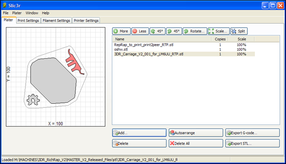
FIGURE 15-13: The Plater window provides a virtual build plate on which you can place your 3D objects before processing.
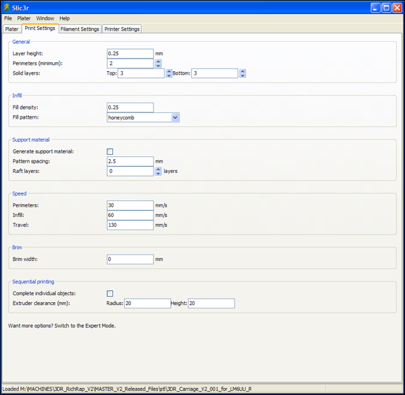
FIGURE 15-14: The Print Settings tab in Slic3r allows you to describe how solid your printed part will be and the speed at which to print it.
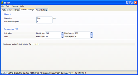
FIGURE 15-15: The Filament Settings tab tells Slic3r what material you’re using and what temperature should be used for the material (filament) being used.
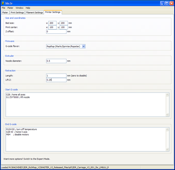
FIGURE 15-16: On the Printer Settings tab, enter the dimensions of your RepRap 3D printer and the type of firmware in your electronics.
Calibrating Your 3D Printer
When your firmware is set up and the RepRap printer’s mechanical movement is mostly calibrated, final preparation for 3D printing encompasses these procedures:
- Making final calibrations of the extruder and hot-end
- Entering these details into the firmware
- Compiling and downloading the firmware again
Don’t be tempted to skip this section. Correct calibration of the extruder and hot-end makes all the difference between an awful-looking print and a stunningly good one.
The procedures in this section use Pronterface (see Figure 15-17). You can run any of the other host programs we discuss in this chapter, but we use Pronterface for this initial setup because it’s easy to use. Pronterface was designed and programmed by Kliment Yanev as an open-source control interface for RepRap 3D printers. You can obtain the full package (called Printrun) at https://github.com/kliment/Printrun.
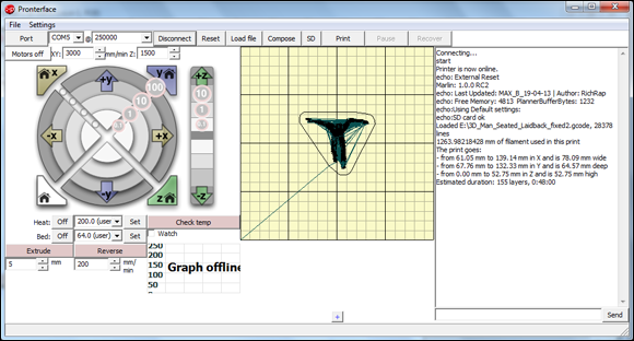
FIGURE 15-17: Pronterface running and connected to a RepRap printer with G-code loaded and ready to print.
Unlike 2D paper printers that appear in all applications as printers, most 3D printers require a host program to prepare, control, and send the specific G-code file. Thus, at this point, you can’t just turn on the machine and press Print. You need to do a little more with a 3D printer. Here are the steps you follow in Pronterface:
- Connect the 3D printer to your computer via USB cable and turn on the printer.
- Select the communication port from the list.
-
Make sure that the correct speed is selected.
For Marlin firmware, this speed is normally 250,000.
-
Click Connect.
If the communication port and speed are set, you see a sign-on message in the right-side window in Pronterface that indicates connection and communication is active. This message signals that you have control of the printer and that it’s ready to accept commands.
Leveling your print bed
The first order of business is making sure that your hot-end nozzle is a set distance from the print surface and that your printing surface is flat and level.
The procedure varies from one 3D printer to the next. Usually, it involves tightening or slackening three or four points on your build bed, which usually is made of PCB material and fixed or held by spring bolts that allow you to level the bed.
Before you level the bed, make sure that the other major assemblies of your 3D printer — especially the moving X carriage and the vertical Z movement — are also level and at equal distance on each side.
The main sensor that positions the hot-end correctly away from the build bed is the Z-axis end-stop. Usually, this sensor is a mechanical switch that can be moved up and down or a magnetic sensor that can be tuned to a set distance by turning a small rotary knob known as a potentiometer. Commonly, a small LED on the end-stop-sensor lights when the end-stop position is reached. If your axis doesn’t stop, or if the LED doesn’t light when the axis is sent to the home position, you may have an incorrect orientation set in your firmware (as discussed in Chapter 13). In such a case, change the X_ENDSTOP_INVERTING = true setting to false in the configuration.h file of the Marlin firmware.
If you use a heated bed, make sure that it’s powered on and at full temperature for a few minutes (to allow everything to expand to where it will be when printing) before you set the mechanical distance of the hot-end nozzle from the bed.
Check the operation of the end-stop switches by commanding each axis in turn to move to the home position. (Figure 15-18 shows the pertinent controls in Pronterface.) Then set the Z-axis distance so that the hot-end nozzle is spaced appropriately far from the bed. The best way to do so is to move the print head to the center of the bed. For a standard RepRap printer, you set this space by moving X by 100mm and Y by 100mm.
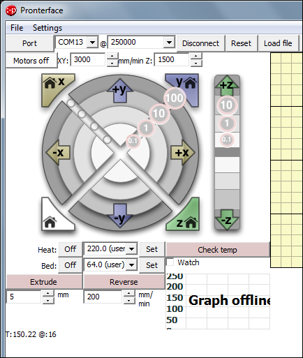
FIGURE 15-18: You can use Pronterface controls to position the print head for leveling the bed, setting the correct distance for the hot-end nozzle, and preheating before printing.
Often, the 3D printer assists you with this process via the LCD screen or user interface. You may have to rotate a screw wheel to adjust the bed position. Then the sensor checks the leveling and informs you if any further adjustment is required. When everything is level, you can continue with printing, knowing that the first layer should go down smoothly and evenly.
The distance you need to achieve depends somewhat on the nozzle size and on how well you leveled the build bed. Partly for this reason, a sheet of glass (which tends to be reasonably flat) is a good choice for the build surface. As a starting point, make sure that you can slide a single sheet of office paper under the nozzle when it’s at the Z home position. Check this gap for uniformity in all four corners and in the center. Use the Z-movement buttons in Pronterface to lift and lower the nozzle. Then you can move the position of your Z end-stop on the Z axis to activate at the correct distance from the print bed. (Use a sheet of office paper as a spacer.) When you home the Z axis in Pronterface by clicking the Z Home button (refer to Figure 15-18), the nozzle should raise then lower until the Z end-stop is triggered. If the spacing is still incorrect, move the Z end-stop slightly and click the Z Home button again.
Tuning your hot-end temperature control
The next stage of setup is calibrating the temperature-control requirements of your hot-end. For this procedure, you enter the command m303 in the bottom-right corner of the Pronterface screen and then click Send (see Figure 15-19). This command has the printer perform several heating and cooling cycles; at the end of these cycles, it gives you the settings you need to enter in the firmware (as discussed in Chapter 13) for DEFAULT_Kp, DEFAULT_Ki, and DEFAULT_Kd in the configuration.h file.
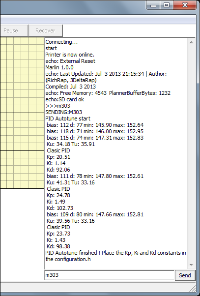
FIGURE 15-19: The G-code command m303 runs an autotune routine that calculates the ideal control loop settings for your firmware.
Write down the values displayed for DEFAULT_Kp, DEFAULT_Ki, and DEFAULT_Kd. You enter these values in the firmware when you complete the final stage of calibration.
Calibrating extruder distance
Before you calculate the last value, you need to ensure that the correct amount of plastic is extruded for a set extruder distance, perform a simple test extrusion, measure the results, and calculate the change. Don’t worry — the process isn’t difficult. We take you through it step by step.
Extruder calibration is really important. It ensures that the firmware knows exactly how much material is being deposited and that Slic3r can rely on your machine for accurate calculations when producing the G-code to print objects.
We discuss the key firmware settings in Chapter 13. Pay particular attention to the fourth number in the DEFAULT_AXIS_STEPS_PER_UNIT list, which specifies how many steps the extruder motor uses to feed 1mm of filament into the hot-end.
You can extrude and reverse the extruder only when it’s up to temperature. This manual control is essential for loading and removing filament and for purging any old material. In Pronterface, you can command the extruder to extrude or reverse the stepper motor by a set distance (specified in millimeters, as shown in Figure 15-20).
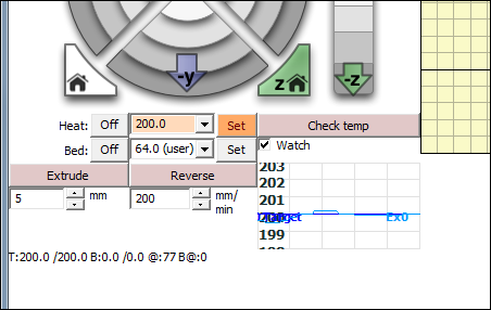
FIGURE 15-20: Controlling the extruder in Pronterface.
Calibrating your extruder ensures that the extruder axis moves exactly the number of steps per unit (each unit being 1mm) and exactly the distance you specify in Pronterface. This way, when the G-code produced by Slic3r commands a 2mm extrusion, you can be sure that the correct amount of material will be deposited. Calculate the correct value by following these steps:
-
Pre-heat your hot-end nozzle by selecting an appropriate temperature for the type of filament material you are using (200 degrees C for PLA and 240 degrees C for ABS).
You don’t need to heat your heated bed for this calibration.
-
When the hot-end is at temperature, insert the filament.
Click the Extrude button in Pronterface. You should then see the highlighted extrude length (5mm) drive the filament into the hot-end every time you click.
At this point, if you notice the extruder stalling, spinning, and attempting to drive the plastic filament a lot more than 5mm, you may need to lower the number in the firmware so that you can calibrate more accurately.Depending on the type of extruder, the type of gearing it has, the electronics that were selected for it, and the way the microstep value was set, the steps-per-unit value should be somewhere between 50 and 1,100. If you’re using 200-step-per-revolution motors with 16x microstepping, one rotation is set at 3,200 steps. One full rotation usually drives a significant amount of filament into your extruder, so if you don’t have any other advice about your extruder, try using a value of 200 for the first test.
- Wrap a strip of tape or a sticker to the incoming filament about 50mm from the extruder’s filament-entry hole.
-
Measure the distance between the tape or sticker and the extruder body before and after the printer extrudes 20mm of filament.
Write this number down.
Suppose that you measure 48mm between the mark and the extruder body. The best way to measure this distance is to use a digital micrometer (see Figure 15-21). A digital micrometer can help you in many ways, including checking whether your printed parts come out as designed and measuring the filament diameter of different coils for setting in Slic3r.
-
Extrude 20mm of plastic filament in 5mm steps, with a delay of a few seconds between steps.
The delay ensures that the printer doesn’t extrude too fast; it reduces the risk that the motor will skip. You should have a smooth motion of filament driven into your hot-end and extruded.
-
Measure the new distance between the mark and the extruder as you did in Step 4.
If your extruder is ideally calibrated, the new remaining distance (in this case) is 28mm. Chances are, however, that this new gap is either bigger or smaller than the 28mm you wanted. You may actually have measured 32mm, meaning that the extruder drove the filament only 16mm instead of the 20mm you expected. In Step 5 you clicked the Extrude button in Pronterface four times (20mm in total) so you should have had a 20mm movement of filament.
-
Calculate the steps-per-unit value.
Use the existing number of extruder steps per unit in your firmware (which you set to 200 in Step 2), and the distance extruded (in this case, 20mm) to calculate the number of motor steps your firmware just moved. Because 200 x 20 = 4,000, this result is the number of motor steps your firmware moved for the 20mm of extruder motion you set. Because you achieved only 16mm of movement, however, you can calculate your actual steps-per-unit value by dividing that 4,000 by 16 to get 250.
You can make the same calculation if the number is higher than 20. It will be lower than the 200 steps you first tested.
-
Enter the new steps-per-unit value in the firmware.
If you enter the change in the extruder’s steps-per-unit value in your firmware from 200 to 250, you achieve the 20mm of movement you requested the next time you perform this operation.
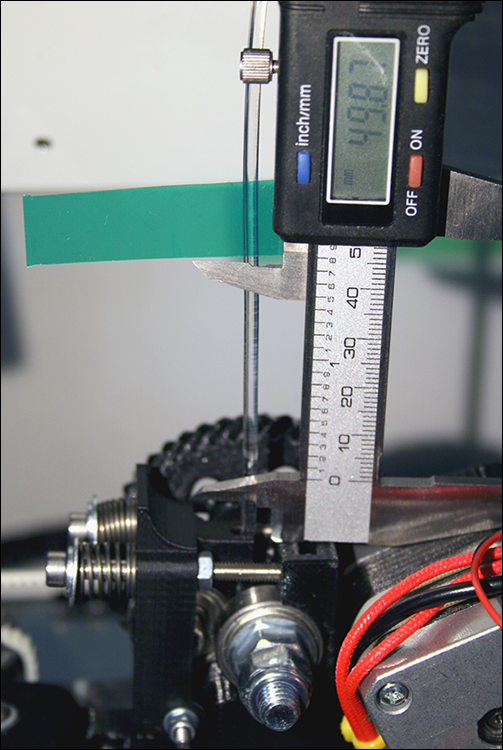
FIGURE 15-21: Use a digital micrometer to measure the distance that the input filament moves when 20mm is extruded.
After updating your firmware with these changes, you’re ready to print your first 3D object.
Printing Objects
Make sure that your 3D printer hasn’t been knocked out of alignment and that your hot-end is still a suitable distance from the build bed before you print. Fortunately, you don’t need to calibrate the temperature of your hot-end and do extruder calibration every time you print; you’ve entered these values into your firmware, and such settings don’t require constant adjustment.
Now you’re ready for your first 3D print. This moment is an exciting one, but don’t get overly ambitious. Instead of printing a complex object at this stage, try printing something easier, such as a simple cube. You can print cubes to test all sorts of things, including materials and settings; they’re great ways to check things. Cubes don’t take long to print and can show you how settings such as Infill and Solid Layers change the way that an object looks.
You can download a simple 20mm cube (20mm x 20mm and 20mm high) at www.youmagine.com/designs/calibration-set-for-3d-printers-extruders-and-materials.
To print the cube, follow these steps:
- Load your cube object into Slic3r.
- Set Infill at 20 (percent).
- Set three solid top and bottom layers.
-
Export the G-code, and load it into Pronterface.
Pronterface shows the object loaded in the middle of the virtual print bed (see Figure 15-22). You can click the object and scroll through the various layers. In Figure 15-22, you see the base layer with a ring around it. This ring isn’t part of the object being printed; Slic3r adds it as the first part to be printed, to prime the plastic flow of the extruder before the object starts to print. The middle sections show the hexagonal infill and (finally) the solid top surfaces.
-
Set your print bed and hot-end to the required temperatures for the material you’re printing, and allow the printer to reach temperature.
Manually setting the 3D printer to pre-heat is usually a good idea, pre-heating allows the machine to get to temperature and balance any thermal expansion slowly before a print is started. If you forget, the G-code does it for you before printing the model. -
Manually extrude some material.
Manually extruding material helps you check that everything is working correctly and homes the printer axis.
-
When the printer is at printing temperature, click Print.
After a slight delay while the G-code checks and stabilizes the temperatures, the print head moves to the middle and starts printing your cube — usually, with a gap-spaced outline to start the flow of plastic. While the first outline is being extruded, look to see whether the plastic is sticking; also make sure that the print head isn’t scraping the surface and isn’t too far away from it.
Figure 15-23 shows a well-bonded first layer. The printer has completed two perimeters. Notice the slight ridge; the infill looks solid and has similar ridges. For the first layer, you shouldn’t see gaps between the individual extruded lines.
If you’re not seeing a good bond of the plastic, stop the printer, and adjust your nozzle head a fraction closer. If material doesn’t escape, and you see the flow stop and start, or if a lot of material squashes out (leaving very high ridges) and the nozzle is dragged through the plastic, the extruder is a little too close to the build bed. Move the nozzle head away.
-
When your cube is finished, confirm that it measures as close as possible to 20mm and 10mm high (see Figure 15-24).
If the cube printed significantly larger or smaller — at 40mm, for example — the
DEFAULT_AXIS_STEPS_PER_UNITvalue probably is set incorrectly for the Z and Y axes. Work out the new value by performing the same steps per millimeter calculation you used for calibrating the extruder extrusion distance in “Calibrating extruder distance.” Make sure that you mark and remember the orientation of the cube when it’s printed. The distance from front to back of the cube on the build plate is the Y measurement, and the distance from left to right is the X axis. New users often find the Z axis to be set incorrectly because many RepRap 3D printers use similar belt-and-pulley drives for X and Y. Other machines may use threaded rods, belts, or lead screws for the Z-axis motion. -
Make sure that your cube’s corners have 90-degree right angles.
If not, make sure that your X-axis carriage is aligned straight across the moving Y axis.
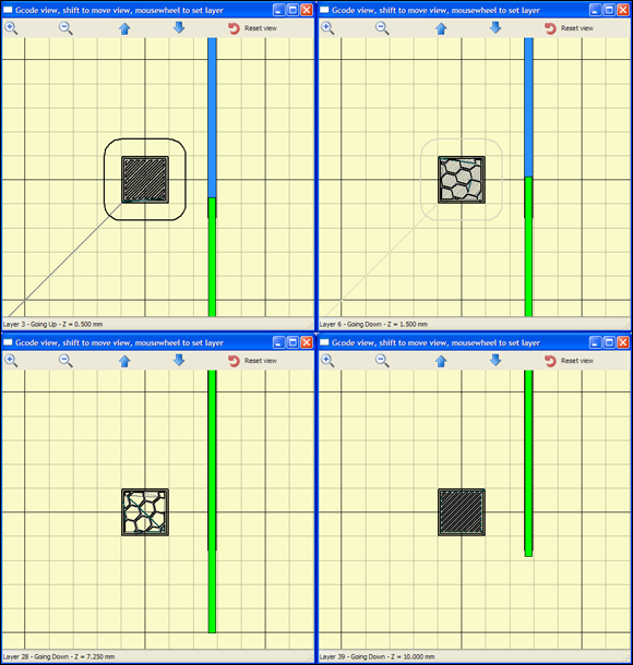
FIGURE 15-22: Pronterface shows your cube loaded in the middle of the virtual print bed.
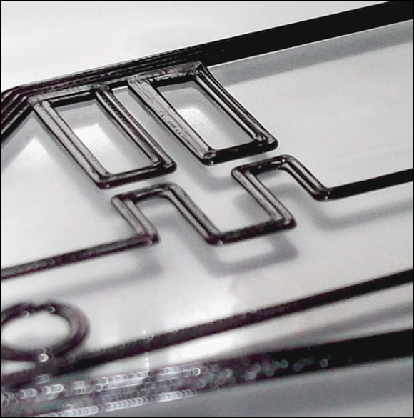
FIGURE 15-23: A well-bonded first layer.
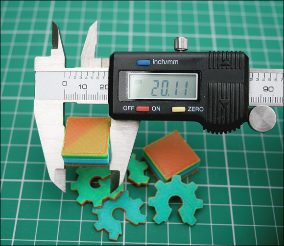
FIGURE 15-24: Make sure that your printed cube measures correctly.
Now you should be able to print more objects and explore the capabilities of your 3D printer. Learning the speeds, temperatures, and settings required to print different objects takes time. The best method is experimentation, because many factors influence 3D printers in various ways.
The next few sections describe a few tricks, tips, and Slic3r settings for various types of 3D-model printing.
Printing vases, pots, and cups
Many models are intended to be printed as hollow (for example, you want a finished cup, but it's designed as a cylinder; see Figure 15-25). Such models are sealed at both ends and usually have details or patterns on the outside. They look solid but are intended to be printed as a single-wall-outline pot or vase. Such designs often produce the best surface quality but can be used only for single-walled objects.
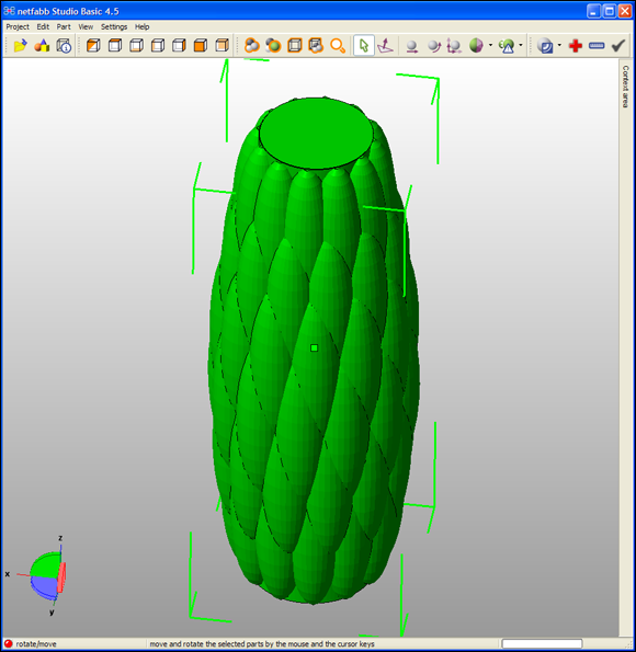
FIGURE 15-25: A hollow-pot design.
Slic3r has a specific setting for cylindrical versions of such objects; it also allows for almost continuous printing without any extruder retractions or machine moves. This setting is called Spiral Vase (see Figure 15-26), which is available in Slic3r’s Expert mode. Set the layer height and number of solid bottom layers. Slic3r automatically removes the top layers, so you end up with a single-wall outline of the object and a solid base.
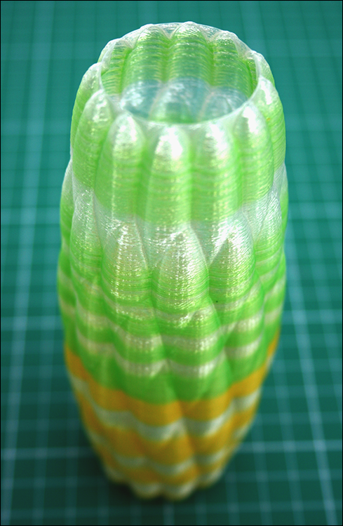
FIGURE 15-26: The hollow-pot 3D model printed as a Spiral Vase. The vertical Z axis never stops being raised slowly, resulting in a seamless print.
Even more impressive, after the solid base layers are printed, the single wall outline is one single extrusion — usually spiraling around while the Z axis moves up ever so slightly as the print head rotates. All this movement makes printing much quicker, with no visible seams on the printed object, because the extruder flow isn’t stopped for a change of layer height.
Using a bigger nozzle is ideal for printing single-walled objects with the Spiral Vase setting. You can still select fine layers, and the wider nozzle provides a thicker single wall, giving your printed object more strength.
Printing large single-piece objects
Printing certain objects — especially large single parts — can be tricky, because the edges of a big part often curl during printing. Some parts are more likely to suffer from this problem than others. If you’re printing parts larger than 100mm, even when using PLA on a heated bed (which doesn’t allow much warping), you may still have some problems. Using ABS for big parts will certainly challenge most home 3D printers. Fortunately, Slic3r has a setting that addresses this problem, and you may find it useful for all sorts of parts.
The Brim option in the Print Settings tab provides a horizontal ring of extending perimeters on the first layer of an object. This option can be highly useful if the object you’re printing is sticking to the base of your build platform or if an object’s corners start to warp during a print.
The Brim option was invented mainly to help big objects stick to the build plate during an extended print. It can also be helpful, or even essential, if you’re printing tiny objects that don’t have a lot of surface area in the first layer. The printed brim peels away from a finished object, with minimal cleanup required.
Printing tiny or highly detailed objects
When printing objects with molten thermoplastic, you require a minimum layer time for the material to be extruded and then cool enough to allow the next layer to be added. If you print each layer too quickly you end up with a soft blob somewhat in the shape you intended, but without accurate features.
If you choose to print tiny objects, consider printing many of them together. By printing multiple smaller parts together the 3D printer can ensure it has a suitable minimum layer time because it spends a longer amount of time printing multiple parts, so each layer takes longer. This may sound like all you are doing is making your 3D print take a longer time to complete, and that's true, but you are also allowing each layer on each part to cool enough to accept more molten plastic on top. If you print just one small part, the slicer will slow down nozzle movements so the layer time is slower, but because the hot-end nozzle head is never too far away from the single part being printed you may still not have enough time to cool the layer.
It's often better to end up with two or three small parts printed together, and they may take only slightly longer to print that one single part due to the minimum layer time condition. This technique has one down side: You may not want copies of a part, and you may start seeing tiny defects on the outside surface of an object where the head moves between the parts. These visual flaws may not be problems for functional parts, but for a model intended for display, you probably require the best possible appearance.
To address the speed problem, you could slow the entire print speed, but there’s a better option: Define a minimum print time per layer in Slic3r. In Expert mode, choose Filament Settings and Cooling ⇒ Enable Auto Cooling. You’ll probably find that this setting is a good one to keep enabled all the time. Read on to find out why.
When you define a minimum layer time, Slic3r knows that it has to automatically calculate and slow any layer to this set speed. The result is that tiny objects automatically print slowly, and bigger parts automatically take longer than the minimum layer time and so are not slowed. Thus, the Auto Cooling setting gives you the best overall print speed and quality.
Automatic cooling is really important with some objects, such as pyramids. A pyramid starts with big layers at the base and print faster as the layers get smaller toward the top. If you don’t set a minimum layer time, the pyramid still looks great until the print reaches the top, where it’s ruined by the very fast printing of tiny layers — which usually results in a blob of plastic instead of a defined, sharp peak. When you set a layer time of around 15 seconds, the print automatically slows as it gets closer to the top, and the model prints well.
You print objects quickly without using the slowing-down method just described, but it takes some time to discern when this technique is appropriate. One way to achieve this result is to use a directional fan to force-cool the layers immediately after they print, but we recommend using this trick only for materials such PLA and for nonheated print beds. You can use 3M painters tape to hold down PLA printed parts when not using a heated bed.
Printing many objects at the same time
As you get more confident with 3D printing, you’ll want to set up a plate of parts and print them at the same time. This approach rarely causes problems, but you may want to use the nozzle-lift function (Lift Z setting) in the printer settings tab in Slic3r. Raising the print nozzle a fraction before a travel move is a good idea when you have a lot of parts on a build surface. This technique can reduce the chance that the printer will accidentally knock off a part or shift the print carriage out of alignment.
For some objects and 3D printers, you may find that rotating a part 45 degrees on the platform makes printing easier, reduces warping, and minimizes the possibility of travel moves that hit corners or the edges of parts. If a print fails or has problems, perform this simple rotation, or reposition the object on the bed before changing other settings.
Improving print quality
As a general rule, slowing print speed improves print quality. Fast travel speed can affect print quality because the print head gets to a new point quickly, and the high acceleration and deceleration sometimes cause unwanted shadows and artifacts on the print. Experiment with machine travel speed before changing other settings.
Temperature also plays an important role in print quality and is especially linked to print speed and layer height. As a general rule, if you start to slow your printing speed below 20mm per second, you should also reduce your printing temperature.
You may decide to print more slowly for a variety of reasons, such as printing a single small object or a part that’s been tricky to print in the past. Most thermoplastic materials print perfectly well at temperatures lower than you’d normally use. Reducing the temperature also helps stop hot plastic from oozing out of the extruder nozzle, which can make a big difference in the quality of fine parts being printed slowly. You have more control of the plastic being extruded with such an approach. Also, you lower pressure in the extruder nozzle, which further improves print quality.
If you’re getting lots of print failures when you print plates of multiple parts, you may have a small mechanical-alignment problem. Check your belts to see whether they’re tight enough. Also check carriage speed. If you’re moving the carriage too fast for the frame design of your 3D printer, try slowing it. If that change doesn’t help, consider tweaking another Expert-mode setting in Slic3r: Avoid Crossing Perimeters. This option tries to move the print head around the outside of a printed layer instead of across the part to reach the other side of the build bed or other object. The setting extends the time required to print an object, but it also improves the quality and reliability of the print.
PLA prints at temperatures as low as 160 degrees C when you’re printing parts slowly, which can produce less oozing and finer detail for smaller parts. You can still use a fan to force-cool the plastic layers, even at such low temperatures.