
Chapter 16
Refining the Design and 3D-Printing Process
IN THIS CHAPTER
![]() Getting productive with 3D printing
Getting productive with 3D printing
![]() Refining the printing process
Refining the printing process
![]() Making 3D printing practical
Making 3D printing practical
![]() Designing for 3D printing
Designing for 3D printing
![]() Postprocessing, recycling, and finishing
Postprocessing, recycling, and finishing
![]() Printing big objects
Printing big objects
![]() Introducing innovations in 3D printing
Introducing innovations in 3D printing
After you’ve built or bought your first 3D printer and calibrated and printed your first few objects, what’s next? In this chapter, we look at how to ensure you are getting the best results from your 3D printer. We consider some practical uses for everyday 3D printing at home, and offer some guidance on designing parts for the 3D-printing process.
Being Productive with 3D Printing
3D printing is more accessible to more people, but being accessible isn’t the same as being usable or user-friendly. As the fundamental technology matures and also reaches speed and material limitations, more innovative processes will be developed to be safer, quicker, and easier for the average user to manage.
Now, the reality check: These changes aren’t going to happen all that soon. Manufacturing free-form objects on demand isn’t easy, and atomic replication of objects isn’t even on the horizon. Even metal 3D printers are still used only in industry due to complex safety systems and requirements.
3D-object repository sites such as YouMagine (https://www.youmagine.com; see Figure 16-1) provide access to thousands of ready-to-print objects, but you have a limited number of ways to change or repurpose the objects on these sites without delving into 3D design. Some 3D models or programs have some customizable features, enabling you to add a name or tweak the size and shape of the object. More often, though, to make significant changes, you need to edit the 3D model directly, which can be an obstacle to adoption of 3D printing for some people who don't have experience in 3D design.

FIGURE 16-1: The 3D-model sharing website YouMagine.
To combat this problem, companies and manufacturers are adding a more user-friendly experience in the form of ready-made material profiles, automatic setting generators (see Figure 16-2), and intelligent 3D-model analysis systems that suggest better ways to print your object. These changes are taking away much of the guesswork and experimentation required to achieve a successful 3D print. You can’t yet click Print and be sure that an object comes out as you expect every time, but that day is getting closer all the time.

FIGURE 16-2: The automatic profile generator for the Sigma 3D printer.
Before 3D printing is widely adopted at the consumer level, designing 3D objects will have to be easier. Companies such as Autodesk and Adobe have spent decades refining and simplifying the 3D design process for both professionals and novice users, and the process is improving all the time. Innovative tablet-based apps, for example, allow organic design and manipulation of 3D designs by touch and gesture.
Refining Your Print Preparations
After you’ve bought or built a desktop 3D printer, what more do you need to do before you dive into 3D printing?
The next few sections discuss some further steps you can take to ensure that your 3D printer is correctly set up and calibrated, including some simple models you can use to refine the material deposition system so that parts fit and are accurately reproduced.
Before you make your first attempt at printing, make sure that the machine is set up correctly — not damaged or out of alignment. Check that the electronics, motors, and sensing stops are operating correctly. Then gather the basic information you need to complete your first 3D print.
Following are our top tips for making sure that your 3D printer is correctly set up and calibrated:
-
Level the build platform and set the first layer distance correctly. A level platform and the correct distance are two of the most important aspects of successful 3D printing. Just because you have a bed-sensing probe or automatic level system, though, don’t expect it to work correctly right out of the box or after you assemble the kit. It’s almost always essential that you manually check and set the offset distance from the probe sensor and the nozzle of the hot-end.
The sensor triggers at a set distance from the build platform, but the tip of the hot-end nozzle usually is slightly farther away than this trigger point. Therefore, you need to set a Z-axis offset. Usually you have a setting on the machine that controls the offset of the nozzle from the build platform. Often you place a sheet of paper onto the build platform and adjust the nozzle up and down, by rotating the control knob on the 3D printer. When this distance is correctly set, a high-quality bed sensor probe (capacitive, inductive, or infrared) should give you highly repeatable results time and time again.
At the start of a 3D print, the sensor checks the platform distance and then moves the extra offset (usually, –0.5mm to –3mm) before starting to print the first layer. Tuning this offset distance and making sure that the build platform is level and flat gives you perfect first-layer results and a greater chance of print success.
-
Make sure that the correct level of power is being fed into your position system. Verifying the power level ensures that the stepper motors don’t lose steps at higher speeds and don’t overheat. Too much power is as bad as not enough. If the power level is set incorrectly, your 3D printer may never operate properly, or it will fail often during printing.
 You usually adjust motor power on the stepper-motor drivers by rotating a small dial called a potentiometer. Many kits come already set to the correct setting, but just as many require you to perform this step.
The exact level of power depends on the motor you’re using and the type of driver installed in the electronics system. Check with the manufacturer to find out what settings you require for the stepper motor’s current (power) limit.
The extruder stepper motor requires a current limit to be set, and this limit may be higher than the limits for the motors used for X, Y, and Z motion. Some electronics control systems can set the motor power via firmware settings you can change on the control panel menu of your 3D printer. Check to see whether your machine can be adjusted through the menu, which is usually much more convenient than having to adjust settings in the firmware code that you then need to recompile and upload to the 3D printer. - Check the extruder calibration. Set the important extruder steps per unit (unit being 1 millimeter) (eSteps) to ensure that the correct amount of plastic material is pushed into the hot-end. The Slicing program uses the eSteps number to calculate the exact flow of material being extruded for the required print move to ensure plastic is not over or under extruded into the model being printed. See “Calibrating extruder distance” in Chapter 15 for instructions on how to check and also update the eSteps setting.
-
Check that the temperatures you set for the hot-end nozzle and the build platform are correct. Making sure that the temperature you set for a plastic material is the same as the temperature you set for the hot-end is really important, because you really don’t want to be melting plastic at the wrong temperature. When the temperature is too low, you risk jamming the nozzle or the extruder system. When the temperature is too high, the material can begin to break down — or, in a worst-case scenario, release gases or burn, causing significant damage.
You can check the temperature in several ways, but using a hand-held temperature sensor is the easiest way. The best sensor for the job is a physical probe that can make direct contact with the nozzle and the heated build platform. (Infrared and laser sensors don’t work as well.)
 The most important piece of advice we can offer you is this: Never leave a 3D printer unattended. Make sure that you have operational smoke alarms near your work area. Also ensure that you have adequate ventilation or fume extraction. If you have any doubts about the printer setup, check with the manufacturer. A 3D printer is often hot moving machinery, and you must treat it with respect.
After you’ve checked and double-checked your printer, you can get ready to print a model. Many manufacturers supply machine profiles and material settings for the slicing program being used for model print preparation. Make sure that you have the correct profile installed, and see whether you require any firmware updates that the manufacturer has issued since you bought the 3D printer.
It’s very tempting to print off something impressive, but to be on the safe side it’s best to start with a basic 20mm cube or some other small part, like the ones shown in Figure 16-3, that can assist you with initial calibration of the printer.

FIGURE 16-3: Printing a number of calibration models helps you refine settings for different materials and nozzle sizes.
A 20mm cube should take around 20 minutes to print, and producing it can really give you the confidence to know the machine is set up accurately, the X, Y, and Z axes are aligned, and material flow is correct. You will get tired of printing cubes, but remember that if you spend some time calibrating now, anything else you print is much more likely to be successful and also dimensionally accurate.
You can download a simple set of 20mm calibration cubes from YouMagine at www.youmagine.com/designs/calibration-set-for-3d-printers-extruders-and-materials.
Examining a Design Example
In this section, we discuss how to design a 3D object as a fully functional part, not a model or prototype. We take a close look at the key design steps and the materials to use.
For this example, Richard designed a small filament spool rack mounting hook (see Figure 16-4). The design was made in FreeCAD to enable mounting multiple spools behind a Prusa i3 MK2 3D printer. The goal was to allow a standard 15mm wooden dowel to be used with 3D-printed custom filament spool adapters so that a wide range of materials could be mounted, thereby facilitating rapid switches from one spool to another.
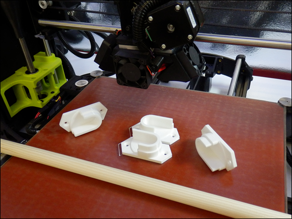
FIGURE 16-4: Several printed spool mounts.
You can download a file for this model, as well as other mounting brackets, from YouMagine at https://www.youmagine.com/designs/filament-spool-holder-brackets-and-adapters.
When designing and printing this part, consider how much weight it’s likely to be supporting. For the purposes of our example, the span from one side to the other is around 80cm, so about nine spools can fit in that space. Normal filament spools weigh about 750g to 1kg each. We assumed a maximum load of 6kg for the printed plastic and fixings because the wooden dowel would start bending at weights higher than this loading. (See Figure 16-5.)

FIGURE 16-5: The simple mounts created for this example.
This mount will be attached to the wall with countersunk wood screws — two on each side should be adequate — but you could add more if you want to support more weight. In that case, you’d also need a thicker wooden dowel.
The back fixing plate needs to be at least 3.5mm thick, and the outline of the U-shape wooden dowel holder protrusion needs added material because the 3D-printed layering process will be a weakness. If not adequate, the printed plastic will be an obvious break point because the layered manufacturing method is not as strong as a solid injection molded part of the same thickness.
For this reason, the cup for holding the dowel has a wider ring around the base to create a stronger, more solid protrusion. The top section of the U-shape cup enables easier positioning of the dowel into the 3D-printed wall bracket, as the dowel will be shorter than the span across the two mounts. You don’t want one end of the dowel to slip out of the mount because the cup doesn’t extend out enough when you lift the opposite end. You could mount or design these holders in a line if you need to raise and lower the height of the spools, especially if you use wider- or smaller-diameter filament spools.
The screws are aligned with the top and bottom points of the base. This allows you to draw a pencil line on the wall or surface and line up the top and bottom of the mount so everything stays vertically straight. Then it’s just a matter of printing it with a suitable material and infill strength.
When you make functional parts, think about how they’ll be used. Adding alignment features or small marks can help users with installing things straight or in line with other parts. In this example, Richard has made the top and bottom of the wall mounting bracket design into a point. (See Figure 16-6.) You can align the top and bottom points to a pencil mark on the wall to ensure the mount is vertically straight. In 3D printing, you can add complexity or customization as you need it. You can design exactly what you need.

FIGURE 16-6: Using 3D design to assist with installing a product.
Designing Parts for 3D Printing
3D-printed parts intended for practical use need to be designed for both the application and the printing process you’re using. In this section, we look at the design aspects and print settings of the example spool mounting bracket. We also look at what materials are appropriate to use for this bracket and similar objects.
As you design a part, include the suggested material type, color, infill level, orientation, and finishing method in the 3D design file so that the machine can read these criteria and advise the user what material to load. Better still is when the printer can automatically fill in settings for processing to ensure a strong or correctly orientated part for manufacture. The adoption and use of new additive manufacturing types like AMF (additive manufacturing format) will allow all these things, including multiple part and multiple materials, the color of object parts, and density of fill levels, to be defined. AMF is not in common use for desktop 3D printers. At this point only a few industrial machines are using the AMF format, but that is likely to change as more emphasis is required on the design to 3D printing process for even desktop machines.
Plastic materials used in 3D printing can range from very hard and brittle to incredibly elastic, soft, and stretchy. The material you use depends on the purpose of the item you’re printing.
The more you understand about the properties of various filament materials — both straight off the roll and as used in simple test objects — the more successful your printing experiences will be. Bending and snapping a length of filament can tell you a lot about how the material will react to impact and load or stress. Sometimes, destroying printed parts helps you understand more about the limits of a particular material.
Adding layer upon layer of semimolten plastic can create a weak point, and if the extruding temperatures of your hot-end were too low for a material, you may get poor layer bonding strength, but you can’t always know until you’ve experienced those situations. Experimentation and research are necessary before you try to produce a usable item.
Printing single-walled objects such as tubes and cylinders along with fully filled 100% solid plates can help you gauge how strong a material will be after 3D printing. You may need to crush, twist, or drop a part to find out some of the material’s properties, such as layer adhesion strength.
Safety first! If you’ve ever snapped a single strand of round spaghetti, you’ve noticed that almost every time, a small section breaks off and flies across the room. The same can be true of filaments or 3D-printed parts. Be very careful when removing parts from your build platform. If you decide to do some strength testing of various plastic filaments or destruction testing of any printed parts, take care. Always wear safety glasses and gloves for protection.
Material
For the spool mounting bracket, you have plenty of options for materials. The spool bracket needs to be stiff and able to take a few knocks and bumps while in use. Richard decided to use a co-polyester for this part because it offers a good overall range of properties for a mechanical, functional object like this bracket. Following are some the plastics Richard considered for this model:
-
Polylactic acid (PLA): This material is routinely used to print functional parts of 3D-printer kits. It’s rigid, has good layer bonding, and is ideal for printing parts larger than 100mm because it has a low tendency to warp or deform during printing.
PLA, however, isn’t as impact-resistant as some other plastic materials and can crack under excessive loads or knocks. Also, due to its low-temperature glass transition point (around 55 degrees C), it can creep (slightly deform) over time, especially when a fastener, like a screw or bolt, is used to compress or pull on the printed layers of a PLA object.
-
Acrylonitrile butadiene styrene (ABS): This material is another common choice for functional parts, but it’s tricky to print with because you need a heated build platform capable of running at least 110 degrees C, as well as a hot-end configured for ABS. Usually, you need to disable the part-cooling fan to help limit warping in the ABS plastic as it builds layer on layer.
The example bracket is small, so it’s suitable for ABS printing, and Richard could have selected ABS for printing this part. Sometimes, the layer bonding strength of ABS isn’t as good as that of PLA, so the better choice was polyester.
The co-polyesters PETG, PETT, and PET are ideal for this functional spool bracket. Their glass transition temperature is around 85 degrees C, which is slightly lower than that of ABS and higher temperature than that of PLA. Polyester materials are very good at layer bonding, which results in parts that are less likely to delaminate than ABS when they’re used or put under stress. Finally, these plastics don’t creep like PLA and have a good level of impact resistance for general use and accidental abuse.
Another material that would be suitable is nylon (polyamide, which shares many of the properties Richard was looking for). The main down side to everyday printing with nylon it that it absorbs moisture from the air when just sitting around, so you need to dry most nylon materials before printing with them. (You have to do this every time you leave the spool out in the open for more than a few hours.) Nylon also resists many finishing techniques, resists many chemicals, and doesn’t sand, file, or polish. Otherwise, nylon is a fantastic 3D-printing material. Not many other home 3D-printing materials can beat its strength and durability. Nylon just takes some experience and patience to use.
Orientation
Often, a 3D model has an orientation that’s friendly to the 3D-printing process and allows material to be added layer on layer with minimal overhangs. But this natural orientation — often with a flat surface facing down and features sticking up vertically — isn’t always the best for strength when the part is in use. When Richard designed this simple spool holder, he was thinking of exactly this problem, so the U-shape holder has more material and is wider at the base, resulting in more bonding strength between vertically oriented plastic layers.
Figure 16-7 shows the sliced G-code layers of the spool mounting bracket in Simplify3D. You can use this visualization to check that the tool-path is likely to print the model as expected and also to review the orientation of features on the model before printing. The model has been placed onto the print bed so the layered build process can print the model without the use of any support material or plastic overhangs. A weak part of the model is where the top of the flat section ends and the bracket starts to print on top of the flat printed layer. This upper printed section has only a small area to bond with the lower plastic layer, so the design uses a wider section to provide more bonding contact. This stops the weaker layer from becoming detached when the part is in use. After the first step is printed we have gained strength in the vulnerable section, so we can reduce the wall thickness of the uppermost layers.
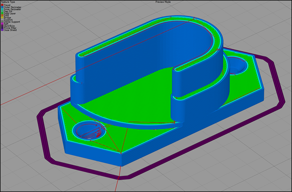
FIGURE 16-7: Sliced G-code showing how each layer bonds to the one before it.
If this part had been designed with a plate to screw to the wall and a thin U-shape protrusion to hold the wooden dowel, the U shape would be likely to snap off the base soon after entering use or after being knocked once too often.
The part could have been designed to be printed in the 90-degree rotation, so the many printed layers would be aligned across the span of the U-shape holder. (See Figure 16-8 and imagine these parts had been printed at a 90-degree rotation to the build platform.) This alignment would make the part significantly stronger due to the fact that each layer of plastic projecting out from the bracket if now in-line with the wooden dowel, so weight of the dowel and its contents does not put pressure onto single layers but a combination of layers at right-angles to the weight. But the layers would now also be aligned across the base rather than on top of one another. This means that when you use a screw to secure the bracket to the wall the screw will force the printed layers apart rather than compress them together. Forcing them apart causes a split and weakens the bracket. As soon as any weight is added, that crack will cause the wall mount to fail. The original orientation compresses the many solid layers when the screw is inserted, which is preferable. This consideration is important, as you don’t want the screw mount to be a point of failure when it’s loaded with heavy spools.

FIGURE 16-8: The key settings are shown here in Cura.
 Most slicing programs allow a wide range of ways to print a 3D model, but correct orientation on the build platform is often the most important aspect.
Layer height
The height of each printed layer determines the appearance of the finished object and contributes some of the strength of the printed part. The relationship of the layer height range you can use with a certain nozzle size is directly related to the width of the printed line of plastic and the bonding strength (surface area) of each line on top of the previous layer. If you need functional parts to be strong but don’t want to wait an extremely long time for them to print, a layer height that’s 50 percent of the nozzle size is both strong and quick to print. The printer Richard used had a 0.5mm nozzle fitted, so he used 0.25mm layer heights. The part didn’t need a super-high-quality finish; it just needed to be strong and solid.
Nozzle size and perimeter outlines
The nozzle size you fit into the 3D printer determines how many perimeter outlines you need to meet the target for wall thickness. Model slicing programs approach the thickness of the outer perimeter wall in two ways:
- Cura: With Cura, you decide on a wall thickness, which is usually a multiple of the nozzle size. For the example part, you’d select 0.5mm for a single perimeter or 1.0mm for two perimeters.
- Slic3r and Simplify3D: In these programs, you select how many perimeter outlines you want to print for the object. (If you choose more outlines than can fit in the allowable space, the slicer creates as many as it can to fill the space.)
Perimeter outlines add strength to a model because they’re always printed together, which creates a solid outer and inner wall of plastic regardless of whether the infill level inside the printed part is important for strength. For some parts, a thick perimeter and low level of infill is stronger than a single perimeter and a higher level of infill.
Infill level
Most newcomers to 3D printing expect finished objects to be solid, and they’re often quite surprised to find that objects are almost always filled with mostly air (typically, 25 percent — or less — of plastic in a zigzag, honeycomb, or regular pattern of lines). Even with a single 0.5mm perimeter and a 25 percent infill level, a 3D-printed part can be very strong. Decorative models often use an infill level of 5 percent or are printed as hollow, with 0 percent infill material.
3D-printed parts used for building RepRap 3D printers are often printed with approximately 30 percent of infill. Some parts for high-torque gears and motor mounts require 50 percent to 60 percent infill. You rarely need to 3D-print a 100 percent (solid) infilled object, which uses a lot of material and can take a long time to print.
For the example spool mount (see Figure 16-9), Richard selected a 75 percent infill level. The part is quite small, and it needs to be strong, with more material-to-material contact on each layer. For a functional mount or bracket on a larger scale, you might print with around 50 percent infill; almost everything else would be 25 percent or less.
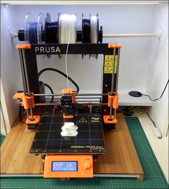
FIGURE 16-9: The finished mounting brackets, wooden dowel, and filament spools fitted and in use.
Postprocessing, Recycling, and Finishing an Object
After completing a 3D print, you have some further options to add strength and a fine or smooth finish. In this section, we discuss some postprocessing and finishing options, along with exciting materials that are now available for desktop 3D printers.
Manual finishing
Sanding, filing, cutting, and polishing are ways to manually refine many 3D-printed plastic materials. You can use polishing wheels and sanding machines, but be sure to run them slowly; otherwise, they tend to melt the plastic rather than smooth or polish it.
Some materials, especially composite metal-filled filaments, can produce a wonderful finish with a little effort and patience. Figure 16-10 shows a 3D-printed object being polished. The stainless-steel, metal-filled filament begins to shine with the application of some manual rubbing and buffing. (You can get the model from Thingiverse at www.thingiverse.com/thing:29114.)
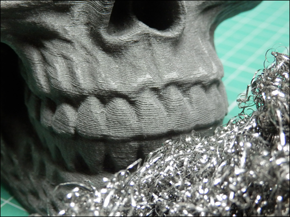
Celtic Skull model designed by artec3d and printed in Proto-Pasta Stainless steel 3D Printing filament.
FIGURE 16-10: A 3D-print object being polished.
Assisted finishing
When an automated or assisted finishing process is desired (for example, the use of a machine to lower a printed part into vapor or solvent baths to make the plastic shine), specific plastic formulations are being created and devices are being developed to help with the postprocessing of 3D-printed objects.
The Polysher, shown in Figure 16-11, uses poly vinyl butyral (PVB) plastic 3D-printing filament to print parts on your desktop 3D printer as normal. You then place the printed parts into the Polysher machine along with a small amount of isopropyl alcohol (IPA). The Polysher vaporizes the IPS solvent and that slightly melts the outer surface of the PVB printed object to smooth out all the fine lines you always see on any 3D-printed object. The Polysher seals in the vapor and controls the generation and duration of smoothing to produce a shiny finish, as shown in Figure 16-12. This process can also make the final object watertight and strengthens the printed model due to the fact the layers have been remelted together. The result is a model that looks like it was injection molded rather than 3D printed. This is basically what every product designer would need to complete the finishing of a 3D-printed model without any hard work.
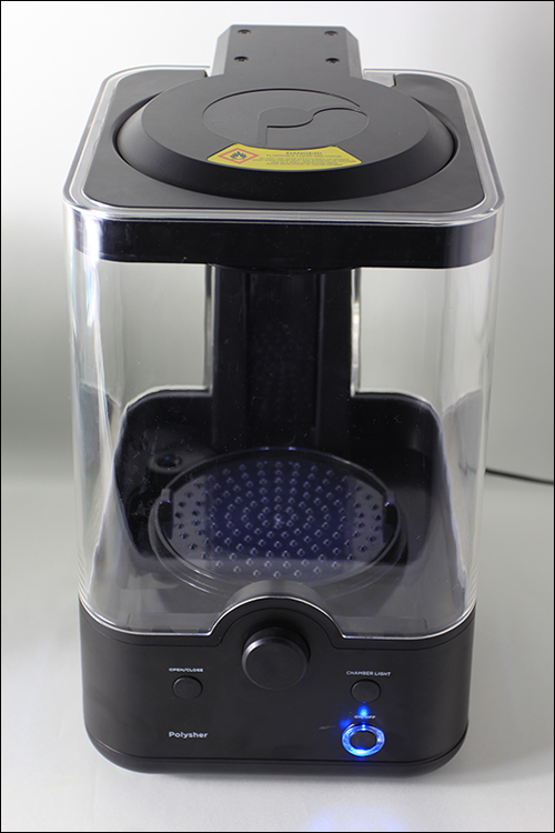
Image courtesy of Polymaker
FIGURE 16-11: The Polysher.
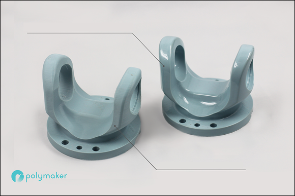
Image courtesy of Polymaker
FIGURE 16-12: Before (left) and after (right) the use of polysmooth material and the Polysher.
Alternative methods of finishing an object can be complex and difficult to manage, so consider carefully whether you want to attempt using them. Using acetone on ABS printed objects, for example, melts the surface and makes it smooth, fuses the layers, and adds strength. The result is a finished, glossy appearance for the 3D-printed object. Take great care, and do your research; acetone and isopropyl alcohol are both flammable. Acetone smoothing of plastic is widely described on the Internet, but we don’t recommend using this finishing process. Unless a professional device similar to the Polysher becomes available for ABS or other materials, avoid acetone smoothing of ABS.
Coatings
Dipping or painting on liquid resins or coating like the XTC-3D from Smooth-On, is a straightforward way to finish a 3D-printed part. This method often adds strength and provides a smooth finish.
One negative aspect of applying coatings is that coatings can change the size of the finished object. They also sometimes hide or fill small details of the model that you may want to remain visible.
Read all manufacturer’s instructions and wear appropriate protection before applying a coating to your object.
Printing Big: Bonding and Joining Parts
Occasionally, you may want to print 3D objects or models that are bigger than your 3D printer’s build area.
If the model isn’t made of smaller parts, you can print oversize objects by cutting the model into sections sized for your 3D printer.
This process is much easier than you may think. You can use several free or open-source applications to split a model into smaller sections. Figure 16-13 shows the use of Netfabb to cut a scaled-up dragon model into smaller parts so that it can be printed on a standard Prusa i3 MK2 3D printer (see the nearby sidebar “Adilinda, the singing serpent”). The model is first scaled up by 600 percent so that the final assembled model will stand 883mm tall rather than 147mm. (See Figure 16-14.)
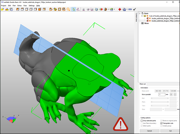
FIGURE 16-13: A large model in the process of being cut into sections.
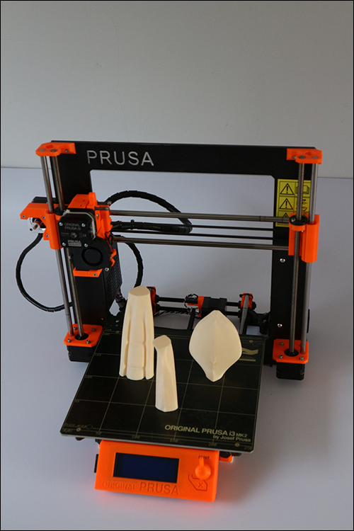
FIGURE 16-14: Sections of the tail scaled up 600 percent and cut into sections, then printed as a plate of parts to be glued back together after 3D printing.
When using an application like Netfabb, you can load in an STL model and alter the scale of the model by clicking on Part-Scale. After scaling up any model, you can then select a cutting point in the X, Y, and Z planes. Perform the cut and as you see the warning triangle in the bottom right of the screen (refer to Figure 16-14); remember to repair each section using the + Icon repair tool before saving each part as a separate STL file.
The sections of any model you cut up still need to be printable, so you may need to rotate sections both before and after cutting in the X, Y, or Z planes. Whatever flat sections you end up with need to be rotated flat to the build platform. Netfabb has an easy Align-to-Bottom-Plane tool for automatically rotating a model to a selected surface.
Figure 16-15 shows the almost-complete model. The various sections were printed in PLA and glued together; any seams or defects are smoothed out with flexible acrylic filler. After the parts are assembled, the object can be sanded and painted as required.
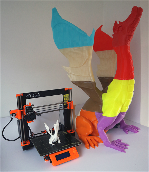
FIGURE 16-15: The almost-complete model.
By cutting a design into components, you can print very large-scale models that can be both strong and light because the honeycomb nature of 3D-printed models allows for minimal use of material.
You can use many paints and fillers to assemble the parts, but some glues don’t stick to certain types of plastic. Make sure to perform a test before trying to assemble a large model. Friction welding or ultrasonic bonding of plastics can help when two parts needs to be joined.
Certain materials also limit how large your components can be. ABS warps significantly more as the printed object gets bigger, for example.
Recycling
One of the most common assumptions people make about 3D printing is that plastic must be recycled and reused over and over again. Unfortunately, it’s not. When you get a failed print, you have no simple way to get that material back into a filament strand that you could use again. Some companies, however, are looking at ways to reuse failed prints and other types of plastic waste, from beverage bottles to doors that may otherwise end up in landfills or the oceans.
Refil in Holland supplies recycled ABS made from car dashboards and polyethylene terephthalate (PET) from plastic bottles. The company is also investigating the use of recycled high-impact polystyrene (HIPS) generated by waste plastic from domestic appliances such as refrigerators. As you might expect, this recycled 3D-printing filament is supplied on eco-friendly recycled cardboard spools (see Figure 16-16).

FIGURE 16-16: A recycled cardboard spool with recycled PET filament from plastic bottles.
The most common way to transport coiled 3D-printing filament is on a plastic spool, which can be around 20 percent of the total shipping weight and is usually discarded after use. Filaments also come in all shapes and sizes that you somehow need to fit on your 3D printer. Few standards exist for size of a spool of 3D-printing filament. If you are lucky, the most common types usually have 750g or 1Kg of material and a 50mm hole in the center. Some 3D printers now have added mounting methods for a typical spool, but just as many leave it to the user to decide what to do with several hundred meters of tightly spooled filament coils (that will tangle and jam halfway into a multi-hour print if they’re not carefully managed).
This chapter includes a guide to designing a filament spool holder bracket to help with the tangling problem. It’s often the first problem new users are faced with, and if you don’t have a good method for mounting and allowing the spool to freely feed you will get countless extruder feed failures or poor quality results.
Some manufacturers are starting to use cardboard or recycled filament spools. ColorFabb is taking this process a step further by introducing a lightweight BioFoam spool for the 3D-printing market (see Figure 16-17). This material starts as PLA beads that expand when hot steam is added to a metal mold.

Image courtesy of ColorFabb BV
FIGURE 16-17: A lightweight, sustainable 3D-printing filament spool based on BioFoam.
Because the Bio-foam is PLA based it can decompose or be recycled for further use. Instead of having a warehouse of heavy empty plastic spools awaiting filament production, these bio-foam spools can be made on demand directly from beads to the filament production line as required (see Figure 16-18), using less space and ultimately costing less to ship to the user.

Image courtesy of ColorFabb BV
FIGURE 16-18: Instead of importing and stockpiling regular plastic spools, the Bio-foam core can be manufactured on-site and used directly on the spooling machines as required.
Using a Web-Based 3D-Printing Interface
As the electronics used in desktop 3D printers become more powerful, more web-based user interfaces are cropping up. These interfaces often allow a 3D printer to be connected, set up, and controlled via a wireless network. In this section, we look at two of the most popular web-based 3D-printing user interfaces.
OctoPrint
If you need to remotely control and monitor your 3D printer or want to network it, take a look at OctoPrint (http://octoprint.org). Designed, maintained, and programmed by Gina Häußge, this open-source Raspberry Pi–based application allows interfacing with almost any 3D printer that has a USB connection. You can use a webcam or your computer’s camera to monitor the live 3D-print process. You can send new files to your 3D printer and start or stop print jobs via network or wireless access through the Raspberry Pi computer.
Duet
The Duet web control (https://www.duet3d.com) runs directly on the 3D printer’s electronic platform and doesn’t require a separate controller (such as a Raspberry Pi). Your 3D printer must use a Duet electronics set or another ARM-based electronics platform that the RepRap firmware can be ported to. The Duet Web Control panel allows remote setup, transfer, and control of printing jobs.