CHAPTER 2
Getting Started with 123D Design
THIS CHAPTER TAKES YOU on an in-depth tour of the Design desktop interface. We’ll look at its menus and features to see what they do, and you’ll learn the capabilities of this app in the process.
Open 123D Design Desktop

Click the 123D Design desktop icon, shown here, and a splash screen of tips will initially appear. Arrow through them, if interested, and then click the X in the upper-right corner to close this screen. You can check the box in the lower-left corner if you don’t want the screen to appear again. (You can always bring the screen back later if you need to reference it.)
Probably the best tip at this stage, however, is to press the F1 key, which brings up a screen of hot keys (or shortcut keys), as shown Figure 2-1. You might want to print this screen and keep it handy as you go through the interface. Also, you should know that the RETURN key finishes an operation, the ESC key cancels an operation, and the DELETE key serves as an eraser.

Figure 2-1 A screen of shortcut keys and navigation tips. (A change unacknowledged yet in this screenshot is that the “Drop on Grid” function, which snaps an object to the grid, is now Select + D).
Once the splash screen is closed, the interface is exposed, as shown in Figure 2-2. It consists of a sketch plane, menu bar, ViewCube, navigation panel, online kits window, and Snap and Units settings.

Figure 2-2 The 123D Design interface
Sketch Plane
Also called the work plane or canvas, the sketch plane is a gridded surface upon which you draw all lines and forms. It can be oriented horizontally or vertically, as shown in Figure 2-3. Sketches and solids snap to the grid lines, making it easy to model in those increments. The origin (point 0,0,0) is in the lower-left corner of the grid, denoted by the large circle.
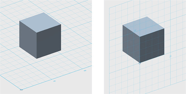
Figure 2-3 The sketch plane is a gridded work surface upon which all lines are drawn. It can be oriented vertically or horizontally.
Menu Bar
The menu bar is a horizontal bar at the top of the screen that contains menus (also called buckets) and functions. If you can’t see them all, drag the screen window so that it’s larger. Let’s start with the menu on the far left, as shown in Figure 2-4.

Figure 2-4 The 123D Design Application menu contains utility functions.
Design Application Menu
This menu contains the functions described next. You’ll need to sign in to your Autodesk account to access the ones that take you to the Web.
![]() New Opens a new, local file and closes the currently open one (you’ll be prompted to save it first, though). If you want multiple files open at the same time, click the desktop icon to open new files.
New Opens a new, local file and closes the currently open one (you’ll be prompted to save it first, though). If you want multiple files open at the same time, click the desktop icon to open new files.
![]() Open Brings up links that let you browse files on your desktop, in your 123D account, or in the 123D Gallery, and to view examples. Before a new file opens, you’ll be prompted to save and close the currently opened one. You need to be signed in to your Autodesk account for this option.
Open Brings up links that let you browse files on your desktop, in your 123D account, or in the 123D Gallery, and to view examples. Before a new file opens, you’ll be prompted to save and close the currently opened one. You need to be signed in to your Autodesk account for this option.
![]() Insert Takes you online to links that let you browse files stored on your desktop, in the cloud, and in the 123D Gallery. It brings the selected file into the currently open one. You need to be signed in to your Autodesk account for this option.
Insert Takes you online to links that let you browse files stored on your desktop, in the cloud, and in the 123D Gallery. It brings the selected file into the currently open one. You need to be signed in to your Autodesk account for this option.
![]() Import SVG Brings in a local .svg file, with options to make it a sketch or solid.
Import SVG Brings in a local .svg file, with options to make it a sketch or solid.
![]() Save Preserves all work done on the current file. You can save it locally with the To My Computer option or online with the To My Projects option.
Save Preserves all work done on the current file. You can save it locally with the To My Computer option or online with the To My Projects option.
![]() Save a Copy Saves the open file locally and makes that copy current.
Save a Copy Saves the open file locally and makes that copy current.
![]() 3D Print Sends the file to Meshmixer for printing preparation and options.
3D Print Sends the file to Meshmixer for printing preparation and options.
![]() Send To Sends the file to 123D Make (desktop), the CNC utility, or a 3D print Web service. All these options are discussed in later chapters.
Send To Sends the file to 123D Make (desktop), the CNC utility, or a 3D print Web service. All these options are discussed in later chapters.
![]() Create 2D Layout Takes you online to start the process of generating construction (2D) views of the model.
Create 2D Layout Takes you online to start the process of generating construction (2D) views of the model.
![]() Export STL Makes a local .stl file of the model.
Export STL Makes a local .stl file of the model.
![]() Exit Closes the program.
Exit Closes the program.
Undo/Redo
This function undoes operations one at a time, all the way to opening the file; it also redoes all undone actions (see Figure 2-5).
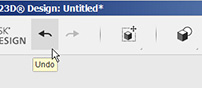
Figure 2-5 Undo and redo all operations, one at a time, by clicking these arrows.
Transform
The Transform menu contains the Move and Scale tools. Move brings up a “box gizmo” that has manipulators for changing the item’s linear and planar positions as well as for rotating it (see Figure 2-6). Scale brings up an arrow to drag for size adjustment and a dialog box to enter numbers (see Figure 2-7). Click the drop-down arrow for the Non Uniform option if you want to change the item’s proportions. Click the TAB key to cycle through the text fields.

Figure 2-6 When the Move tool is selected, a “box gizmo” appears that lets you to change an item’s location and position.
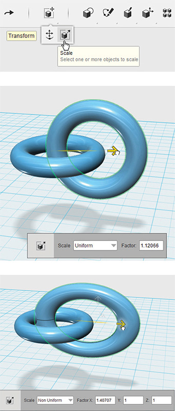
Figure 2-7 The Scale tool lets you to change an item’s size, either uniformly or non-uniformly.
Primitives
The Primitives menu contains 3D forms, also called solids, and 2D shapes (see Figure 2-8). Click a solid and move (don’t drag) it to the sketch plane. This is called cruising. When a primitive is first “cruised” from its submenu, it can be snapped to the center of another primitive’s face (snapping occurs at the white cruise widget—that is, the “handle” where the mouse grabs it).
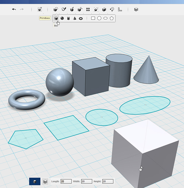
Figure 2-8 The Primitives menu contains simple forms and shapes. They can be “cruised” from the submenu to the sketch plane or to the center of another primitive’s face.
When a primitive is cruised into the canvas, a dialog box appears at the bottom of the screen. You can accept the default measurements or type in new ones; press the TAB key to switch text fields. Click the primitive in place after typing the sizes. Primitives cannot be cruised again, nor can their sizes be changed via this dialog box again (instead, use the Scale tool’s Non Uniform option, shown in Figure 2-7).
Sketch
Some of this menu’s tools—Rectangle, Circle, Ellipse, and Polygon—are premade shapes, whereas others, such as Polyline, Spline, 2-Point and 3-Point Arcs, let you draw your own shapes (see Figure 2-9, upper left). Fillet, Trim, and Extend let you edit sketches; Offset copies and places a sketch a specified distance from the original; Project puts a sketch onto another surface. Note the pop-up boxes in Figure 2-9. These are prompts that instruct what steps to take while using a tool. All tools generate them. Pay attention to these boxes, because if an operation isn’t working, it may be that you aren’t doing what you’re prompted to do.

Figure 2-9 Sketch and edit shapes, polylines, splines, and arcs. Sketch tools can trim, fillet, extend, offset, and project lines.
Construct
The Construct menu’s tools turn sketches into complex forms by extruding, sweeping, revolving, and lofting them (see Figure 2-10). Extrude turns a sketch into a solid. It also cuts through a solid. Sweep extrudes a sketch along a path. Revolve rotates a sketch around an axis, and Loft interpolates a form between sketches. Each tool has multiple options that are accessed via a drop-down menu on the glyph that appears when activated.
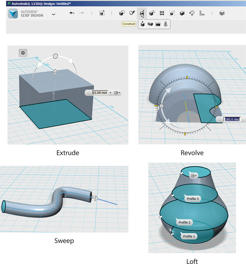
Figure 2-10 The Construct menu’s Extrude, Sweep, Revolve and Loft tools create complex 3D forms from 2D sketches.
Modify
The Modify menu’s tools—Press/Pull, Tweak, Split Face, Fillet, Chamfer, Split Solid, and Shell—change existing solids. Press/Pull lengthens or shortens a solid’s face as well as cuts through a solid, and Tweak warps a solid (see Figure 2-11). Chamfer angles an edge, Fillet rounds an edge, and Shell hollows out a solid (see Figure 2-12). Finally, Split Face breaks a face into two faces, and Split Solid breaks a solid into two pieces (see Figure 2-13). Like the Construct tools, each Modify tool has multiple options.

Figure 2-11 The Modify menu has tools for changing solids. Shown here are Press/Pull, which lengthens or shortens the face of a solid, and Tweak, which warps it.
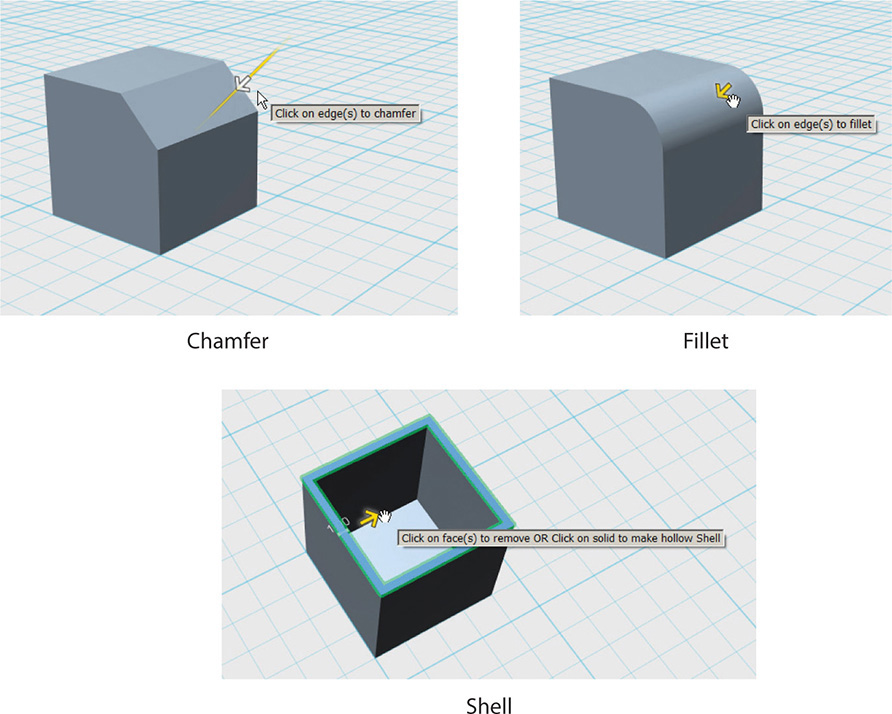
Figure 2-12 Chamfer and Fillet change the model’s edges. Shell hollows out a solid.

Figure 2-13 Split Face divides a face into two; Split Solid divides the whole form into two forms.
Pattern
Tools on the Pattern menu array (that is, copy and arrange) sketches and solids (see Figure 2-14). The array can be rectangular, circular, or along a path. A sketch or solid can also be mirrored.
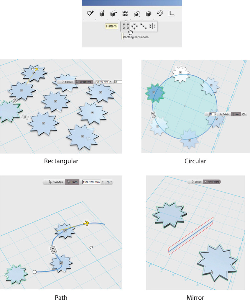
Figure 2-14 Sketches and solids can be arrayed and mirrored.
Grouping
The Grouping menu “paperclips” multiple items together so they can be selected and moved as one. They can later be ungrouped. Double-clicking a group highlights the items individually, enabling them to be worked on separately (see Figure 2-15).
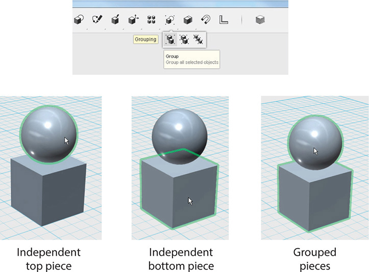
Figure 2-15 Ungrouped items highlight individually when selected. Grouped items highlight together.
Combine
The Combine menu contains the Boolean operations Join, Cut, and Intersect. Unlike grouping, combining alters solids permanently; hence, they cannot later be uncombined. This action can only be done on solids, not shapes or shelled (hollowed out) solids. The three Combine actions are detailed in the following list:
![]() Merge welds forms together. Note that the Chamfer and Fillet operations give different results on merged edges than on grouped or single-item edges. Figure 2-16 shows a chamfered edge of a cylinder combined with a box, and a chamfered edge of a cylinder grouped with a box.
Merge welds forms together. Note that the Chamfer and Fillet operations give different results on merged edges than on grouped or single-item edges. Figure 2-16 shows a chamfered edge of a cylinder combined with a box, and a chamfered edge of a cylinder grouped with a box.
![]() Subtract removes one intersecting form from another (see Figure 2-17).
Subtract removes one intersecting form from another (see Figure 2-17).
![]() Intersect leaves the overlapping parts of multiple objects and deletes everything else (see Figure 2-18).
Intersect leaves the overlapping parts of multiple objects and deletes everything else (see Figure 2-18).

Figure 2-16 A chamfer looks different when applied to a combined edge versus a grouped edge.

Figure 2-17 Subtract removes this shape from the box it intersects.

Figure 2-18 Intersect keeps the overlapping parts of multiple solids and deletes everything else.
Snap
You use the Snap tool to place two items together by clicking their faces (see Figure 2-19).

Figure 2-19 Click on the faces you want to snap together.
Measure
The Measure tool tells you the angle, area, volume, and edge length as well as the distance between pieces (see Figure 2-20).

Figure 2-20 Click the edges of these boxes with the Measure tool to obtain their lengths and the distance between them.
Material
The Material menu offers colors and textures that can be applied to the model (see Figure 2-21). It is only for display purposes only and has nothing to do with a physical 3D print.
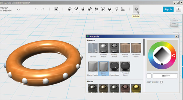
Figure 2-21 Paint materials on the model by selecting the pieces and then clicking a Materials swatch.
Go Premium, Sign In, and Help
The Go Premium menu takes you to a screen with information about Premium (pay) membership benefits and a link to sign up. The Sign In menu, shown in Figure 2-22, takes you to the 123D website, where you can access data about your account, a private message box, cloud-saved files, and (for Premium members) the LayOut feature. There’s also a link to a gallery of models made by other users. The Help menu links to online sources such as the 123D blog, support forum, and tutorial videos. The Quick Start Tips option reopens the splash screen of tips (also shown in Figure 2-22).
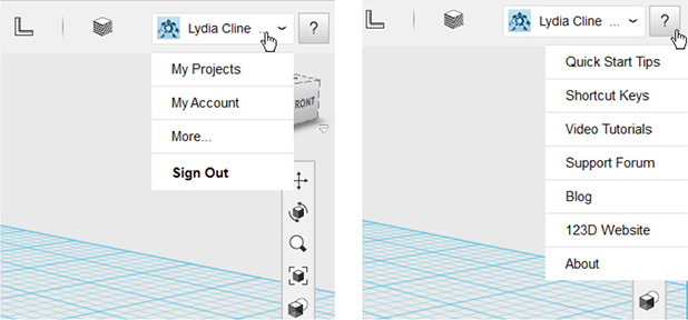
Figure 2-22 The Sign In and Help menus contain online links to your account and places to learn more about the software.
ViewCube
The ViewCube, shown in Figure 2-23, displays the model’s orientation on the work plane. Click the left mouse button on the Cube, drag to rotate it, and watch the model rotate along with the Cube. Click the Cube’s sides to view the model orthographically (that is, as a top, front, or side view). Hover the mouse over the Cube to make a house icon and a drop-down arrow appear. Clicking the house icon returns the sketch plane to its default position; clicking the drop-down arrow provides options to view the model in perspective or orthographically. (The Go Home option does the same thing as the house icon.) An orthographic view lacks the line convergence of perspective, which is useful when you’re aligning forms because you can see their alignments better than in perspective view. A model set to display orthographically will remain that way until changed back.

Figure 2-23 The ViewCube shows the model’s orientation on the work plane. Mouse over it to make a house icon and drop-down arrow appear.
Navigation Panel
The navigation panel, shown in Figure 2-24, contains tools that let you view and display the model in different ways:
![]() Pan This tool slides the model around the screen. You can pan more efficiently by pressing and holding the mouse’s scroll wheel down.
Pan This tool slides the model around the screen. You can pan more efficiently by pressing and holding the mouse’s scroll wheel down.
![]() Orbit This tool whirls you, the viewer, around the model, so you can see it from all angles and heights. Your position relative to the model moves, not the model itself. You can orbit more efficiently by dragging the mouse while holding its right button down.
Orbit This tool whirls you, the viewer, around the model, so you can see it from all angles and heights. Your position relative to the model moves, not the model itself. You can orbit more efficiently by dragging the mouse while holding its right button down.
![]() Zoom This tool gives you a magnified view of the model (think telephoto lens) to see small details, or reduces your view of it (think wide-angle lens) so you can see the big picture. You can zoom more efficiently by rotating the scroll wheel up and down.
Zoom This tool gives you a magnified view of the model (think telephoto lens) to see small details, or reduces your view of it (think wide-angle lens) so you can see the big picture. You can zoom more efficiently by rotating the scroll wheel up and down.
![]() Fit This tool fills the screen up with the model. If your model hides off in a corner after you click it, you’ve got little pieces you drew earlier still hanging around. Find and erase them, and your model will come back. Clicking Fit is a handy way to locate “lost” pieces.
Fit This tool fills the screen up with the model. If your model hides off in a corner after you click it, you’ve got little pieces you drew earlier still hanging around. Find and erase them, and your model will come back. Clicking Fit is a handy way to locate “lost” pieces.

Figure 2-24 Use Pan, Orbit, Zoom, and Fit on the navigation panel to view the model from different angles.
If you have a two-button mouse with a middle scroll wheel, roll the wheel up and down with your index finger to zoom in and out; press and hold it down to pan.
Now look at the last four icons on the panel. The box/circle icon displays the model with materials and outlines, materials only, and outlines only (see Figure 2-25). The box/eye icon hides sketches, solid models, and mesh models separately (mesh models being any .stl or .obj files you import). The group/magnet icon offers the option of automatically grouping forms when they’re snapped together. By default, this feature is on (that is, it groups). The grid/eye icon displays or hides the sketch plane.
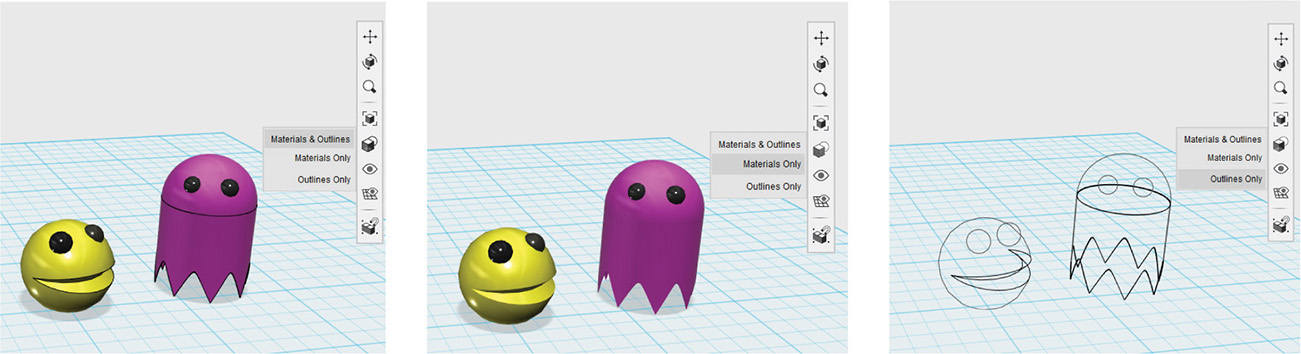
Figure 2-25 Display the model’s materials and outlines, materials only, or outlines only.
Online Kits Window
The small white arrow in the blue rectangle (under and to the right of the navigation panel) accesses the online parts bin. Bins are themed collections of fully editable, scaled models made by the 123D team. An Internet connection is needed because these bins are stored online and load after you open the window. Open the models by dragging them onto the canvas. Click the drop-down arrow at the top of the window to see a collapsed menu of other choices. Text, robots, space vehicles, gadgets, and more are available (see Figure 2-26).

Figure 2-26 Click the white arrow to open the online kits window and then click the drop-down arrow at the top to see a collapsed menu of themed collections. Shown here are the Smart Primitives and Robot Heads kits.
You don’t have to be signed in to your Autodesk account to access the bins.
Snap and Units
The two functions at the bottom of the screen—Snap and Units—help you model accurately (see Figure 2-27). Snap restricts movement to specific intervals. Select one between 0.1 and 10, or turn Snap off to simply glide the forms and sketches across the work plane. Units lets you choose millimeters (mm), centimeters (cm), or inches (in) to model in. Millimeters are the most precise for 3D printing, but if you’re more comfortable working in inches, do so; just change the units to mm before sending the model to the Makerbot.
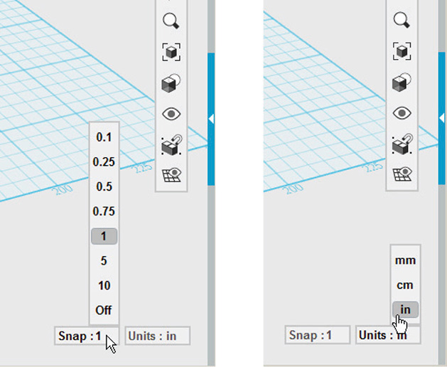
Figure 2-27 Snap and Units offer choices for applying measurements to the model.
A file remembers any interface changes you make (for example, selecting new units) after it is closed and reopened. However, new files will still have the default settings, so the changes will need to be reset.
Text Tool
In Chapter 1, I said that the 123D apps quickly iterate. Well, Design just iterated! A Text tool was added to the menu bar (Figure 2-28). Click on the T and then click on the workplane to place it, type in the dialog box that appears, and push ENTER.
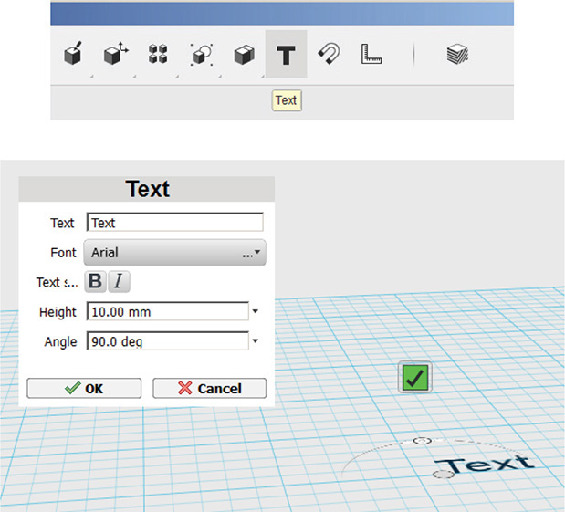
Figure 2-28 The Sketch Text tool.
Summary
In this chapter you began learning how to use the 123D Design desktop app by exploring its interface. Now that you know the features, what they do, and where to find them, join me in Chapter 3, where we’ll start modeling.