CHAPTER 7
For the Kids! Tinkercad
TINKERCAD IS A WEB-BASED program written to introduce elementary school kids, or anyone with little computer experience, to solid modeling and 3D printing. Therefore, it is simpler than 123D Design, doesn’t require as much computing horsepower, and works best on small projects. Yet it has some powerful features, such as the ability to import .stl and .svg files, export .stl and Minecraft-ready files, and make unique forms with a feature called the Shape Generator. Because it is also free with an affordable subscription option, it’s very popular in K-12 education settings. Both free and paid accounts can store an unlimited number of files. Check out what other tinkerers are making at www.tinkercad.com/things/ (see Figure 7-1).

Figure 7-1 A page of models at www.tinkercad.com/things/
In this chapter, you’ll learn how Tinkercad is used via projects that incorporate the features just discussed. Tinkercad is accessible from almost any device, across the Windows, Mac, and Linux platforms. Your browser must be HTML5/WebGL-enabled, and Chrome works best. Point it to www.tinkercad.com. You’ll be asked to make an account; it’s separate from the account used for the rest of the 123D suite. Once you make that account, your dashboard will open. Because you don’t have any projects, it will mostly display tutorial projects, as shown in Figure 7-2. We’ll discuss the dashboard in depth later; right now, just click the Create New Design button, and let’s tinker!
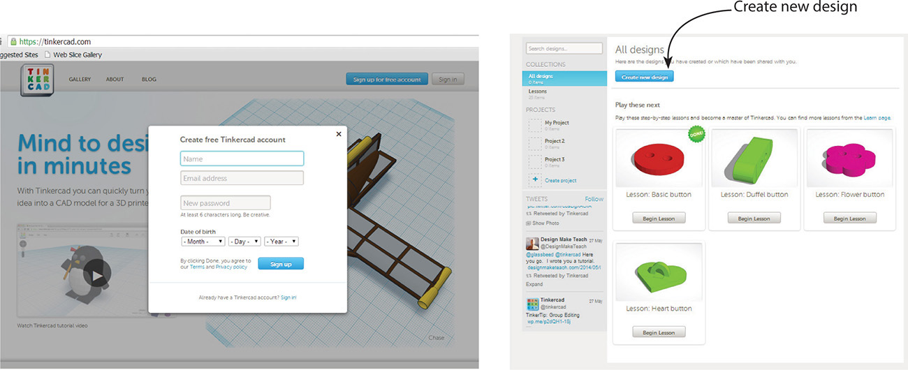
Figure 7-2 After creating a Tinkercad account, your dashboard will open.
The Tinkercad Interface
The Tinkercad interface, shown in Figure 7-3, consists of the Tinkercad graphic, a menu bar, navigation wheel, fit and zoom icons, grid adjustment settings, an arrow that exposes a library panel, and a workplane. Here’s a description of the items you’ll find there:
![]() Generated filename Tinkercad assigns a random name to your file. You can rename it through the Properties options box.
Generated filename Tinkercad assigns a random name to your file. You can rename it through the Properties options box.
![]() Menu bar The menu bar contains the following icons:
Menu bar The menu bar contains the following icons:
![]() Tinkercad graphic Click this to go to your dashboard.
Tinkercad graphic Click this to go to your dashboard.
• Design Contains utility functions, Properties options, download links, upload links to third-party service bureaus, and links to the Thingiverse and a gallery of shared models.
• Edit Contains the Copy, Paste, Duplicate, and Delete functions for parts within the file.
• Help Contains links to tutorial videos and other information.
• Undo Undoes each step, one at a time.
• Redo Redoes each step, one at a time.
• Adjust Contains the Align and Mirror functions. Align lets you select-snap the positions of multiple parts so their edges or centers line up. Mirror lets you reverse a part’s position.
• Group Holds selected parts of the model together so they can be moved together.
• Ungroup Returns selected grouped parts back to individual parts. Ungroup may need to be clicked multiple times to ungroup nested groups (groups inside larger groups).
• Navigation wheel Click the house icon to return the workplane to the default position. Click the arrows to move the workplane in those directions.
• Fit View to Selection Select something on the model and click this item. The select part will fill the screen. If nothing is selected, the whole model will fill the screen.
• Zoom buttons The plus sign gives you a closer view of the model; the minus sign gives you a farther-away view.
• Mouse The mouse is your other navigation tool. Rotate the scroll wheel to zoom in and out; hold it down to pan (slide the model around the screen); hold down the right button to turn (which orbits you around the model); hold the left button to move (drag) the model into a different location on the workplane.
• Question mark Click this item for a pop-up chart of navigation keys.
• Grid adjustments Snap Grid aligns the model with the nearest intersection, in increments of your choosing. Set it to Off to move the model freely. Edit Grid lets you choose units, the width and height of the squares, and a preset for a specific 3D printer (see Figure 7-4).
• Arrow This opens and closes the Library panel.
• Library panel This contains the parts collections: Shape Generators, Helpers, Geometric, Holes, Letters, Number, Symbols, and Extras. Figure 7-5a shows the collapsed libraries; click the icons at the top to quickly access a specific collection, handy when most of the collections are open. Figure 7-5b shows the specific collections.
• Workplane This is the flat, gridded surface on which all modeling is done. Unlike the workplane in other apps, it has no origin. Parts snap to workplanes, not to each other.

Figure 7-3 The Tinkercad interface

Figure 7-4 Grid adjustments. Here, a Makerbot and 1/8” snap are selected.

Figure 7-5 (a) The collapsed Libraries panel. (b) The Library panel’s collections.
Tinker Basics: Drag, Delete, Select, Move, and Save
Models are built by dragging parts (click a part and hold down the left mouse button) from the Library panel and altering them. Press a keyboard arrow key to move an item 1 mm. Abort a dragging operation with the ESC key. Otherwise, the ESC key has limited functionality here, so typically you’ll complete an operation and click Undo if you don’t want to keep it. To delete a part, click to highlight it and then press the DELETE key.
The SHIFT key serves several purposes. When moving a part, hold the SHIFT key down to keep the part aligned with the x or y axis. When using the arrow key to move a part, press SHIFT to move it 10 cm. When scaling a part, hold the SHIFT key down to keep the shape proportional along all axes. And when rotating a part, hold the SHIFT key down to snap the rotation at 45° increments.
Select a part by clicking it. Select multiple parts by clicking and holding down the SHIFT key. Alternatively, select multiple parts by dragging a crossing window around them with the mouse (click the left button, drag, and release). This window will select everything it touches, regardless of whether the part is entirely inside the window. A crossing window needs to be started on a workplane, not on a part. Clicking and dragging a part moves that part on the workplane.
Tinkercad saves your work automatically. It remembers everything you do; hence, it can undo steps even after you close and reopen the file. However, once you click Design | Save, you cannot redo past the point of that save. Future redos will affect changes made after the save.
Tinker a Building Block
Let’s tinker the building block shown in Figure 7-6. In Grid Properties, set Units to Inches, select the preset Makerbot Replicator 2, and set Snap Grid to 1/8”. Note the workplane now has the proportions of the Makerbot’s build plate.

Figure 7-6 A building block
Drag a cube from the menu panel’s Geometric library to the workplane (see Figure 7-7).
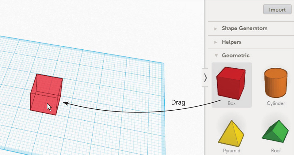
Figure 7-7 Drag a cube to the workplane.
Once the cube is on the workplane, move it by clicking anywhere on it and dragging it to the new location. Note that it is displayed as a three-point perspective. There is no orthographic (2D) mode. Because a 1/8” snap was set, the cube will snap to intersections at those increments.
Change the Block’s Size with Manipulators
Click the cube (see Figure 7-8). It will be outlined in blue, indicating that it’s highlighted and ready for editing. Manipulator icons also appear: three curved arrows, an arrowhead, and white and black grips. An Inspector box appears as well. It contains options to change the part’s color (highlight the part and click the color swatch to bring up a palette), to turn the part into a hole (highlight the part and click the hole swatch), and to lock all changes made so they can’t be inadvertently undone. Figure 7-9 shows the manipulators in use. They are:
![]() Curved arrows The curved arrows rotate and tilt the cube. The active arrow is black; the inactive ones are gray.
Curved arrows The curved arrows rotate and tilt the cube. The active arrow is black; the inactive ones are gray.
![]() Arrowhead The arrowhead moves the whole cube up and down.
Arrowhead The arrowhead moves the whole cube up and down.
![]() Grips The white grip in the middle is used to drag the block taller (drag up) and scale the block proportionately around its center (drag left or right and hold down the SHIFT key). The other white grips scale along two axes, but not around the center. Again, hold down the SHIFT key to scale proportionally when dragging them; otherwise, the proportions will change. The black grips scale along one axis. Hover the mouse over any grip to see the part’s dimensions (see Figure 7-10).
Grips The white grip in the middle is used to drag the block taller (drag up) and scale the block proportionately around its center (drag left or right and hold down the SHIFT key). The other white grips scale along two axes, but not around the center. Again, hold down the SHIFT key to scale proportionally when dragging them; otherwise, the proportions will change. The black grips scale along one axis. Hover the mouse over any grip to see the part’s dimensions (see Figure 7-10).

Figure 7-8 Click the cube to highlight it. This makes a thin blue outline, manipulator icons, and the Inspector box appear.
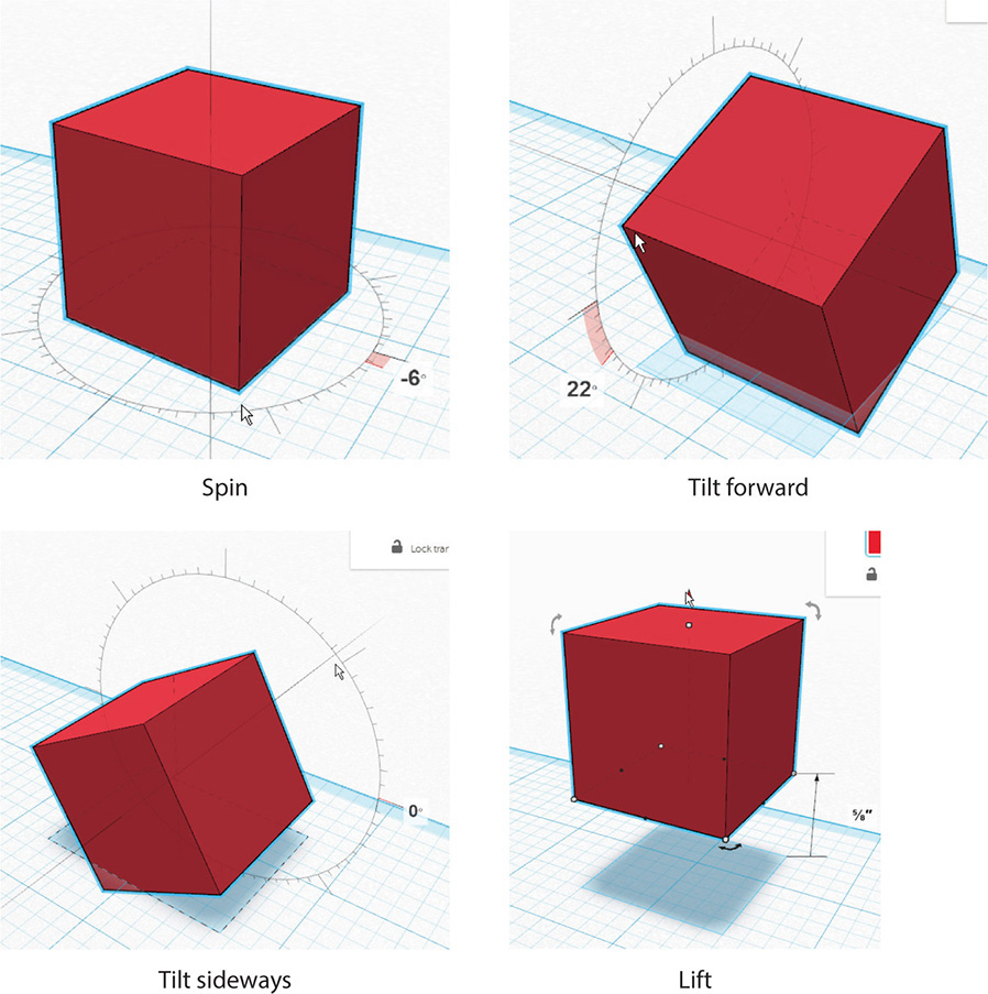
Figure 7-9 Move the cube with the manipulators.
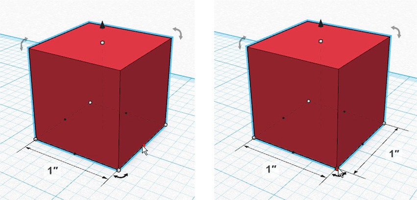
Figure 7-10 Click a white grip to see two dimensions; click a black button to see one dimension.
To change the block’s size, grab the lower-left white grip and drag that side left until the block is 2-1/2” long (see Figure 7-11). Grab the upper-right white grip and drag that side until the block is 1-1/4” deep. Then grab the top-middle white grip and drag it up until the block is 3/4” high.

Figure 7-11 Scale the block by dragging the white grips.
Snap Parts Together with the Workplane
All parts must go on a workplane. Although placing parts together without putting them first on a workplane is possible, it’s much harder. So drag a workplane from the Helper collection onto a part (it can go on a straight, angled, or round surface), and then drag any other Library part to that workplane. The part will snap to the plane. Parts already in the model can be snapped together with workplanes, too. Drag a workplane onto one part, and then drag another part to that workplane. All dimension numbers that appear on a part are relative to the plane it is on or snapped to.
Once a workplane is clicked onto a part, it becomes the active workplane. Helper workplanes are orange to distinguish them from the original blue workplane. To reactivate the original workplane, drag a new Helper workplane onto it.
Just to see how this works, drag a new workplane from the Helper collection onto the default workplane to make it active again (see Figure 7-12).
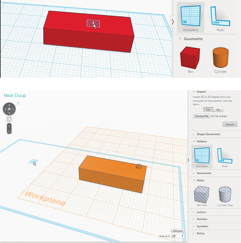
Figure 7-12 Make the default workplane active by dragging a Helper workplane onto it.
Make the Studs with the Cylinder Part
Here’s how to use a workplane and cylinder to make the block’s studs.
Bring in a Helper workplane on which to build the studs by clicking Helpers | Workplane and dragging the plane onto the top of the block (see Figure 7-13).

Figure 7-13 Drag a workplane from the Helper collection onto the top of the block.
Drag a cylinder onto the block by clicking the Geometric | Cylinder collection and dragging a cylinder on top of the workplane (see Figure 7-14). Click to select it, and then move the grips (hold the SHIFT key down to maintain proportions) until the cylinder is the desired size. For this project, I sized it 1/8” tall and 1/4” in diameter.
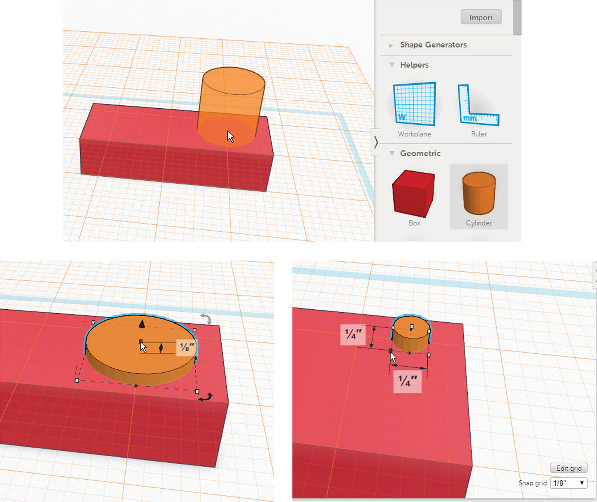
Figure 7-14 Drag a cylinder onto the block and use the grips to make it 1/8” tall and 1/4” in diameter.
Make a Hole with the Hole Part and Grouping
Round and square holes are made with the Cylinder Hole and Box Hole parts in the Hole collection. Drag a hole onto a part in the workspace. The hole will remain separate until it and the part are grouped together. You can turn any part into a hole by clicking it and then clicking the Hole graphic in the Inspector box.
To cut a round hole in the cylinder, first drag a workplane on top of the cylinder (left graphic in Figure 7-15). Then from the Holes collection, drag the Cylinder Hole onto that workplane, centered on the cylinder (right graphic in Figure 7-15). Since a 1/8” snap is set, the hole will snap to 1/8” grid line intersections. There should be a grid intersection at the center of the cylinder to snap to. Alternatively, if you just want to freely move the hole part, set the Snap Grid to Off.

Figure 7-15 Drag a workplane onto the block and then drag a hole part onto it.
Hold the SHIFT key down and drag the hole part’s center white grip inward to scale it smaller around its center. When it’s the desired diameter, drag the black arrowhead to make it taller, ensuring the hole part goes completely through the cylinder. Then select both the cylinder and hole either by dragging a crossing window around them with the mouse (click, drag, and release) or by clicking both parts while holding the SHIFT key down. Then click Group at the top of the screen. The hole part will disappear and in its place will be an actual hole cut through the cylinder (see Figure 7-16a).

Figure 7-16 (a) Scale the hole part, select it and the cylinder, and group them together to cut a hole through the cylinder. (b) Hole parts only cut to the depth they’re inserted.
Hole parts only cut to the depth that they’re inserted. If you pushed the hole part just a little bit into the cylinder instead of all the way through it, the result would be a hole burned into it rather than cut through it (see Figure 7-16b). This technique is how you could make a raised border.
Grouping holds loose parts together so they can be moved as one. And as you just saw, grouping a hole part with another part cuts a hole. Grouped parts can be edited independently by double-clicking them (two fast clicks) . They can be ungrouped any time by highlighting them and clicking Ungroup. Ungrouping the cylinder and hole will turn the hole back into a hole part. Models should be grouped together when finished so that individual parts won’t get inadvertently moved.
Copy and Smart Duplicate
You can copy a part by highlighting it and pressing CTRL-C (hold the CTRL key down and then press C). Then, click where on the workplane you want the copy to go and press CTRL-V. If a second part is highlighted before you press CTRL-V, the copy will snap to that part. If you want a second copy, you’ll need to highlight the part and press CTRL-C/CTRL-V again.
The Smart Duplicate feature automatically makes multiple duplicates and remembers their offset distances. To use this feature, select a part and press CTRL-D. This duplicates it and puts the duplicate over the original. Drag the duplicate off the original and place it where you want it. If you press CTRL-D again, a second copy will appear the same distance from the first as the first is from the original. Let’s give the Smart Duplicate feature a try:
1. Duplicate the stud by dragging a workplane on top of the block, selecting the stud, and then pressing CTRL-D. Drag the duplicate off the original and place it where you want it (see Figure 7-17).
2. Duplicate both studs by selecting the pair, pressing CTRL-D, and moving the duplicates. You can then select and duplicate all four to make eight studs total (see Figure 7-18).

Figure 7-17 Duplicate the stud by highlighting it, typing CTRL-D, and dragging the duplicate off the original.
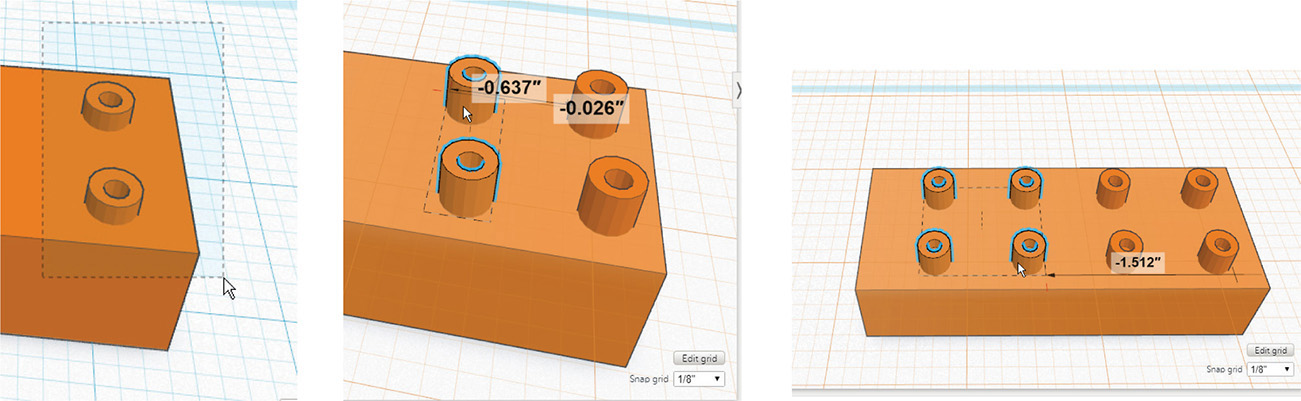
Figure 7-18 Duplicate the studs until there are eight total.
If the studs look too tall, adjust their height. Select them by clicking each one while holding down the SHIFT key, and then drag the manipulator arrow down until the studs are the desired height (see Figure 7-19). Finally, group the block and studs together by dragging a crossing window around them and clicking Group. This enables you to move all the parts as one unit. Done!

Figure 7-19 Make the studs shorter, if needed, by dragging the arrowhead down.
When you group multiple parts, they’ll take on one color, typically that of the farthest-left part. However, when you double-click individual parts to edit them, their original color reappears. Colors don’t have any use other than for presentation purposes, because the physical model will be the color of the printer filament.
The Ruler
The ruler is a tool that measures along two axes. It verifies existing sizes and distances and can be used to change a part’s size and location. Let’s demonstrate how it works on the block. Follow these steps:
1. Drag the ruler from the Helper menu and place it at the block’s lower corner (see Figure 7-20). If you want to place it on a top corner, drag a workplane on top of the block first and then drag the ruler to it. The ruler defaults to the upper-right quadrant, but clicking the circle cycles it through the other three quadrants. You can also drag the circle to move the ruler anywhere on the workplane. The ruler will snap to the grid unless the grid is set to Off.
2. Click anywhere on the block and the following ruler manipulators will appear: an X, dimension lines on all three axes, a black rotator arrow, and two arrowheads (see Figure 7-21a). Click the X to exit the ruler. Click the arrowheads to toggle between midpoint and corner. Midpoint adds a dimension line from one end of the block to the center, and corner shows a dimension from one end of the block to the other (see Figure 7-21b). Click the curved arrow to rotate the block (see Figure 7-21c); hold down the SHIFT key to rotate it in 45° increments.
3. The x,y coordinates (0,0) that appear near the rotator arrow mark the ruler’s origin (see Figure 7-22). Hover the mouse over each coordinate to make it active (it will turn red), overtype a number, and then click anywhere on the workplane. The block will slide that distance (see Figure 7-23). If instead of (0,0) there are other numbers, the block isn’t at the ruler’s origin. You can overtype those numbers with zeros if you want to place it there.
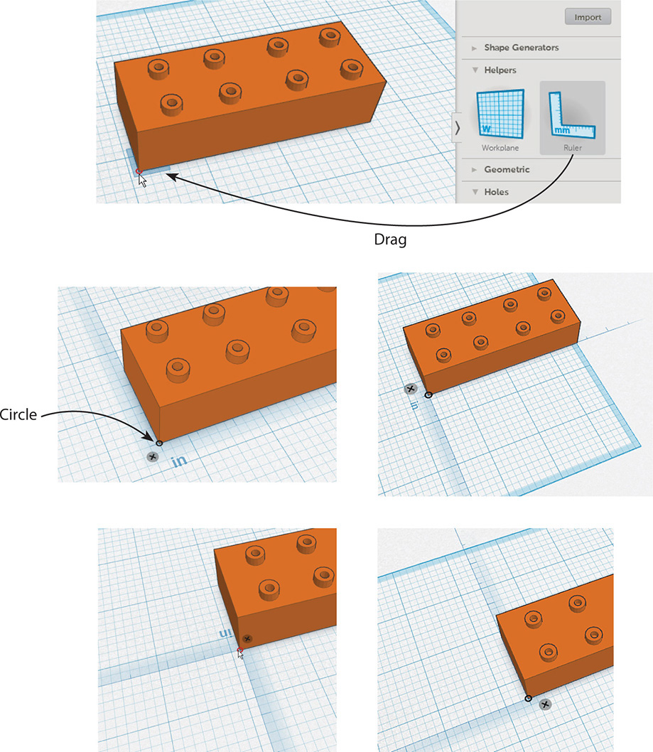
Figure 7-20 Drag the ruler to the block’s lower corner. Change its quadrant location by clicking the circle.

Figure 7-21 (a) Click the block to see its dimensions and manipulators. (b) Toggle between corner and midpoint to see different dimension placements. (c) Click the arrow to rotate the block.
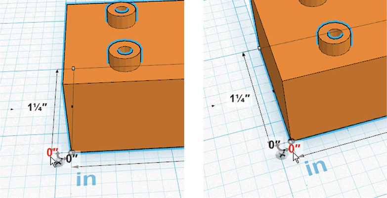
Figure 7-22 (0,0) is the ruler’s origin. Hover over each zero to select it. Select and overtype it if you want to change the block’s location on the workplane.
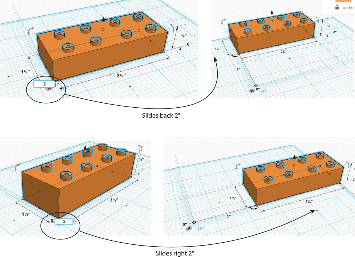
Figure 7-23 Overtype the 0, and the block will slide to the new coordinate location along the x or y axis.
Each dimension number—the distance between the endpoints’ arrowheads—can be clicked and overtyped. After overtyping, click the workplane, and the block will change size (see Figure 7-24).
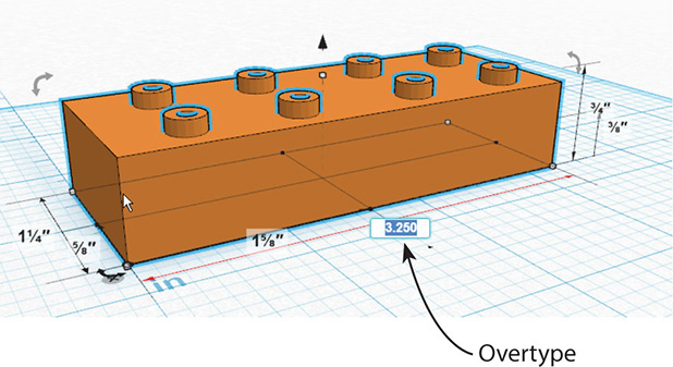
Figure 7-24 Overtype the dimension numbers to change the block’s size.
The Dashboard
When you exit the file by selecting Design | Close, your dashboard will appear (see Figure 7-25a). At the top is a vertical bar with links to editing your profile, the dashboard, the Tinkercad gallery (this is separate from the 123D gallery), video tutorials, a search field for the Tinkercad gallery, and a sign out link. On the left is a vertical bar that contains a search field for just your models (called “designs”), a link to thumbnails of your models, a list of your “projects” (the term for the model plus any file uploaded to accompany it), and a link to Tinkercad on Twitter.

Figure 7-25 (a) The Dashboard. (b) Hover the mouse in a thumbnail’s upper-left corner to see the Tinker This button and gear icon. (c) Click the thumbnail to see a larger image of the model and download options.
In the middle of the dashboard are thumbnails of all your models. Hover the mouse in the upper-left corner of a thumbnail to see a Tinker This button and gear icon (see Figure 7-25b). Click the gear icon to edit the model’s properties, duplicate it, move it to another project, or delete it. The Properties options include renaming the model, choosing its visibility (keep it private or display it in the Tinkercad gallery), and choosing a copyright license. The copyrights choices are from the Creative Commons, a nonprofit organization that promotes open education.
Click a thumbnail too see a larger image with download (export) options (see Figure 7-25c). The Tinker This button opens the file. Note the Creative Commons icons in the lower-right corner. Click them for information about this model’s copyright choices.
To share a Tinkercad file with a friend, just copy and e-mail its URL. Multiple people can view a file simultaneously, but only one can work on it; a pop-up will appear that asks whether the viewer wants to reclaim rights to work on it. To let friends make the file their own, upload it to the Tinkercad gallery, where they can duplicate it.
Download Options
When you click the Download for 3D Printing button shown in Figure 7-25c, you’ll get four options: .stl, .obj, .svg, .x3d colors, and .xrml colors. The .stl and .obj files can be imported into 123D Design, Meshmixer, and Make for further development. You’ll also get an .svg (2D) download option that provides a cross-section suitable for laser cutting, a feature similar to one in 123D Make. Minecraft fans can download a schematic file to import into MCEdit (the Minecraft editor). A link that has more instructions about that is at the end of this chapter.
Tinker a Stamp with the Align and Mirror Tools
For this project, we’ll tinker an ink stamp that says “Be Happy.” Set the units to inches and the snap to 1/16”. This small snap allows finer movement than larger snaps do.
To make the stamp base, drag a cube from the Geometric library. Make it a 4”-long and 1/2”-high block either by dragging its grips until the correct-size numbers appear or by putting the ruler on it and overtyping the existing dimensions with new ones. Then drag a workplane on top of the block (see Figure 7-27).
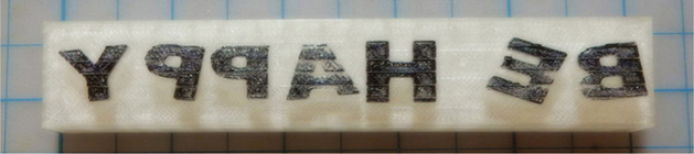
Figure 7-26 The printed stamp.
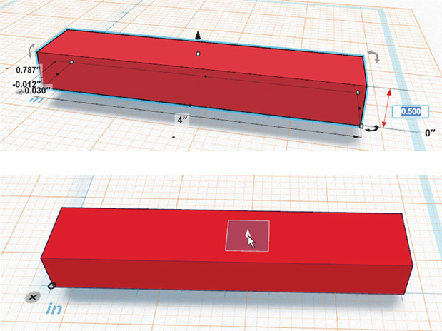
Figure 7-27 The cube is turned into a 4”×1/2” base with the ruler. Then a workplane is dragged on top of it.
Drag letters from the Letters library and line them up by snapping their undersides to the grid (see Figure 7-28). For interest, click each to highlight, then drag into random positions. Rotate some of the letters for extra interest.

Figure 7-28 Drag letters onto the base, move and rotate them.
To align the letters, first select them all by clicking each while holding down the SHIFT key. Using a crossing window would select the base along with them, although in this particular case it wouldn’t matter if the base got selected, too. Next, click Adjust | Align (see Figure 7-29). Handles will appear; hover the mouse over each for a preview of the alignment (see Figure 7-30). Then click on the one you want (see Figure 7-31). You might want to group the letters at this point to make operating on them together easier.

Figure 7-29 Select the letters and click Align.

Figure 7-30 When Align is clicked, handles appear; hover over them for previews of the alignment.

Figure 7-31 Click the alignment wanted.
Mirror the letters so they’ll appear properly when stamped. Select them all and click Adjust | Mirror (see Figure 7-32). Three handles appear; click one and the letters will mirror.
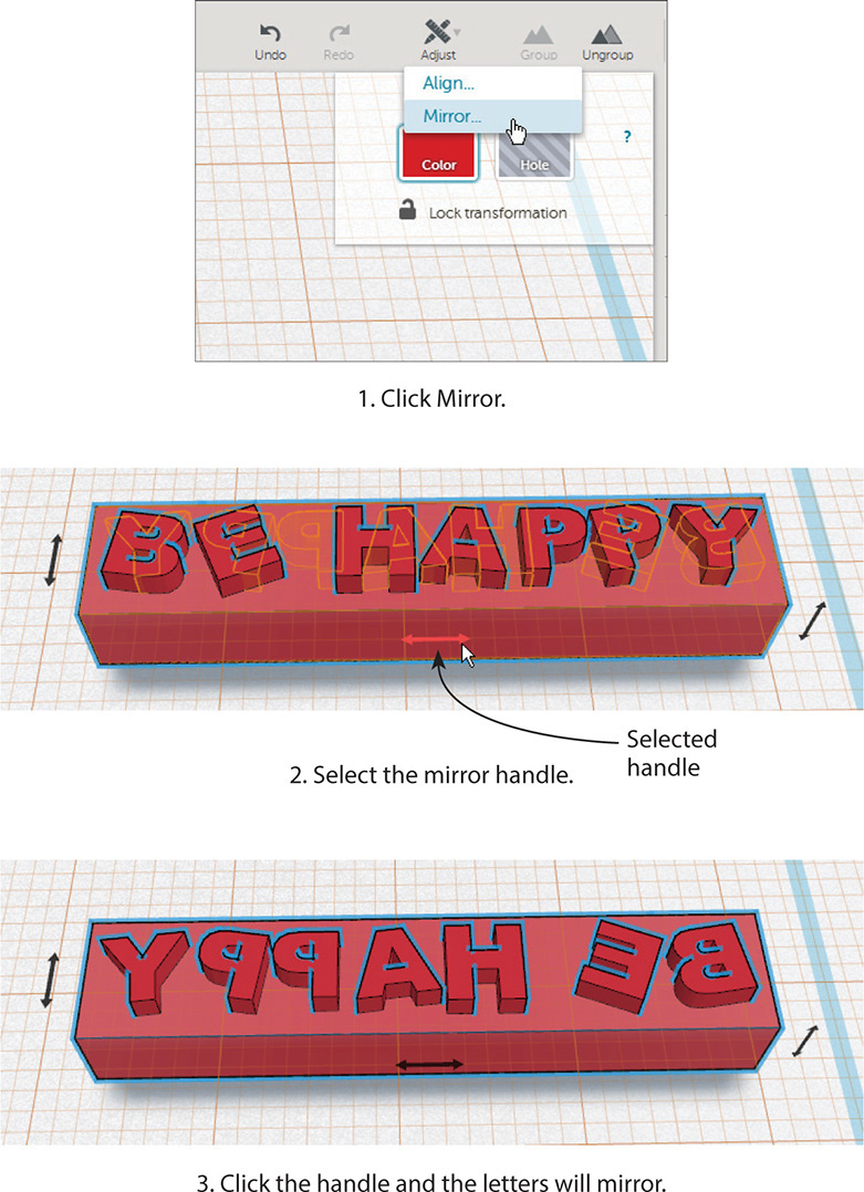
Figure 7-32 Mirroring the letters.
Finally, intersect the letters with the base. If you previously grouped both the letters and base together, ungroup them by selecting them and clicking Ungroup. Then group just the letters together and push them into the base (see Figure 7-33). Protrude them enough to make a clear stamp. Finally, adjust the letters’ height relative to the base, as shown in Figure 7-33.
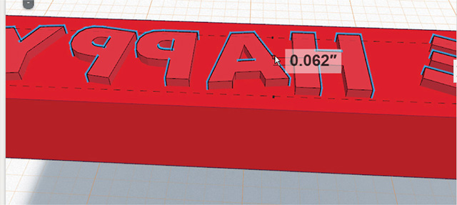
Figure 7-33 Push the grouped letters into the base to adjust their height.
The letters don’t need to protrude much from the base, just enough to make a clear stamp. If you’ve previously grouped the letters with the base, ungroup them by selecting the group and clicking Ungroup. The letters need to be grouped with each other, however, and then pushed down into the base.
To be fully functional, the stamp needs to be printed with a rubber-like material to absorb ink or be paired with a self-setting rubber product such as Sugru. When using the latter, you would push non-mirrored letters into the block instead of protruding them from it, and mold the Sugru over it.
Tinker a Ring with an Imported SVG File
In this project we’ll make the ring shown in Figure 7-34. To begin, set the grid properties to inches and set the snap to 1/16”. Now follow these steps:
1. Drag a torus from the Geometric library onto the workplane and rotate it 90° (see Figure 7-35). See the plane that appears in the center of the ring? Drag a cube out and snap to it.
2. Grab the small arrowhead at the top of the cube to move it to the top of the torus, and then drag down the white grip in the cube’s middle to make it thinner (see Figure 7-36). Next, drag the white grip inward while holding the SHIFT key to make it smaller and maintain its proportions.
3. Make an .svg file like the one shown in Figure 7-37. This is easily done in Inkscape, a free illustration program. Download it at www.inkscape.org. I used the calligraphy tool to sketch “Be Happy” and then saved the file as an .svg. Tinkercad can only import small files, so keep your sketch simple and under 10KB.
4. 
On the menu panel, click File | Import File. Navigate to the .svg file (its icon will probably look like the Firefox or Chrome graphic) and then click Import (see Figure 7-38). The file may import very large, so zoom out if you can’t see it properly. Note that the .svg file entered as an extrusion, and you can adjust it to any thickness desired.
5. Scale the .svg file by dragging the middle white grip inward while holding down the SHIFT key to maintain proportion. Drag a workplane onto the ring and then drag the .svg file onto it. You may need to fine-tune the scaling and placement (turn off the grid snap if needed). Then push the .svg file into the ring a bit with the arrowhead (see Figure 7-39).
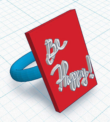
Figure 7-34 A ring made with an imported .svg file.

Figure 7-35 Drag a torus to the workplane and rotate it. Then snap a cube to the plane in its center.

Figure 7-36 Move the cube to the top of the ring and then adjust its size.

Figure 7-37 This sketch was made in Inkscape and saved as an .svg file.

Figure 7-38 Import the .svg file via File | Import File on the menu panel. Here it has imported very large.

Figure 7-39 Scale the .svg file, move it to the ring, and then push it into the ring.
If you want to adjust the ring’s size further, each part will have to be scaled separately, even when grouped. Remember to drag a workplane on the part before dragging the ruler out.
Tinker Other People’s Models
Building on other people’s models can save lots of time. Browse the Tinkercad gallery at www.tinkercad.com/things/. When you see something you like, click it and then click the Copy & Tinker button at the bottom (see Figure 7-40). This opens the model in a new file that will be saved to your dashboard. Be aware that its original history doesn’t copy with it.
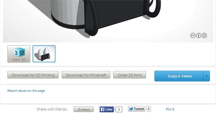
Figure 7-40 Find a model in the Tinkercad gallery, and then click the Copy & Tinker button to make it yours.
Import an STL File of a Phone Case and Customize It
How does a phone case with your name sound? Browse the 123D Gallery (www.123dapp.com/search/gallery) or www.thingiverse.com (see Figure 7-41) to find a blank one. Download its .stl file and import it into Tinkercad the same way you imported the .svg file: click Choose File, navigate to it, and then click Import (see Figure 7-42). Now you can make it your own! I’ll make this one my own by cutting my name into it. Here are the steps:
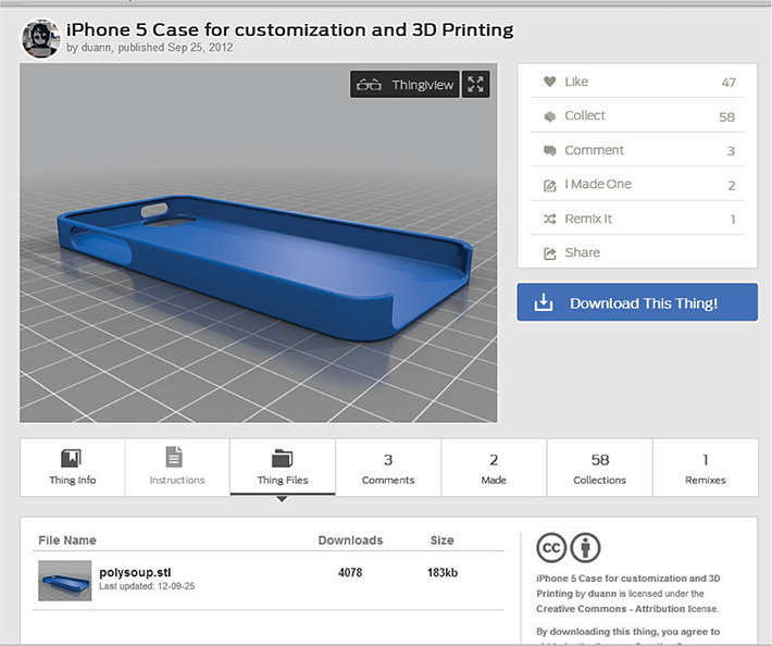
Figure 7-41 A phone case from Thingiverse.com.

Figure 7-42 Import the .stl file into Tinkercad.
Flip the case, drag a workplane onto top of it, and drag letters onto the workplane from the Letters library (see Figure 7-43). Set a 1/8” grid snap to make aligning the bottom of the letters to the grid easier.

Figure 7-43 Adding letters to the case.
Move the letters into place, as shown in Figure 7-44. Select them by clicking each while holding down the SHIFT key. You can group them at this point if you’d like, which will make operating on them as a whole easier. Next, rotate and drag them to the desired location; align to finesse them if needed.

Figure 7-44 Rotate the letters, move them into place, and align if necessary.
To cut the letters out, we first need to push them into the case (see Figure 7-45). They must intersect through the whole depth of the case, not just sit on top of it or pushed a little bit into it. Select all the letters (or the group of letters) and click Hole from the Inspector box. This turns the letters into letter hole parts. Group the hole parts with the case, and the hole parts turn into holes (see Figure 7-46).

Figure 7-45 Cutting the letters out.
Import an .Stl File Directly from the Web
You don’t have to download an .stl file before importing it into Tinkercad. You can import it with just an URL address (see Figure 7-47)! Find something you want from Thingiverse and open its page. Click on the Thing Files folder at the bottom of the page to make the .stl link appear. Then right-click on the .stl link and click Copy Link Address.

Figure 7-46 The customized phone case.

Figure 7-47 Importing an .stl file via its URL.
Back in Tinkercad, click on Import | URL and paste the link into the text field. Click the Import button and the .stl file will appear.
Manage Large Files by Removing Memory History
Tinkercad works best with small files. When a file becomes large and complex, it runs slowly. One way to deal with this is to erase the memory history. This can be done by duplicating the file because duplicate files don’t retain any memory prior to the duplication. Another way is to download the file, or a complicated part of it, as an .stl and reimport that .stl into the file or into a new file. All memory prior to the reimport will be lost, making the .stl, for all practical purposes, a primitive geometric form. Both these actions are done through the dashboard.
Tinkercad as an STL File Repairer
Mesh models often have holes or non-manifold edges (an edge shared by more than two polygons). This makes them non-printable. The 123D Meshmixer app fixes such problems, so all the apps except Tinkercad are sent to it for printing preparation. Tinkercad does not send its files there because it heals bad .stl files itself upon import. It will import any .stl file no matter how bad its mesh is, and turn it into a watertight one. A quick way to fix unprintable .stl files is to import them into Tinkercad and export them out again. Note, however, that the model might get changed a bit in the process. If you don’t like the result, or want more control over that result, import the .stl into Meshmixer and make the changes yourself. Know that Tinkercad does have a limit on polygon size. If your .stl doesn’t import, it’s probably too big.
Shape Generators
Shape Generators are parts that contain JavaScript programming. This enables you to edit them way beyond Tinkercad’s simple tools. Shape Generators are dragged out of the Library panel like any other part, and can intersect, be grouped with other parts, turned into holes, and anything else the native parts can do. They’re made by both the Tinkercad team and the user community. Although the Library panel has a nice selection (see Figure 7-48), you can find more in the Thingiverse (be sure to include “shape generator” in the search terms).
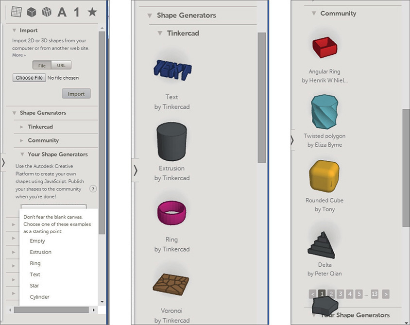
Figure 7-48 Shape Generator collections by the Tinkercad team and user community.
You don’t have to know JavaScript yourself to edit a Shape Generator. The programmer defines how it can be manipulated and provides a control panel for doing so. Figures 7-49 through 7-52 show four edited Shape Generators.
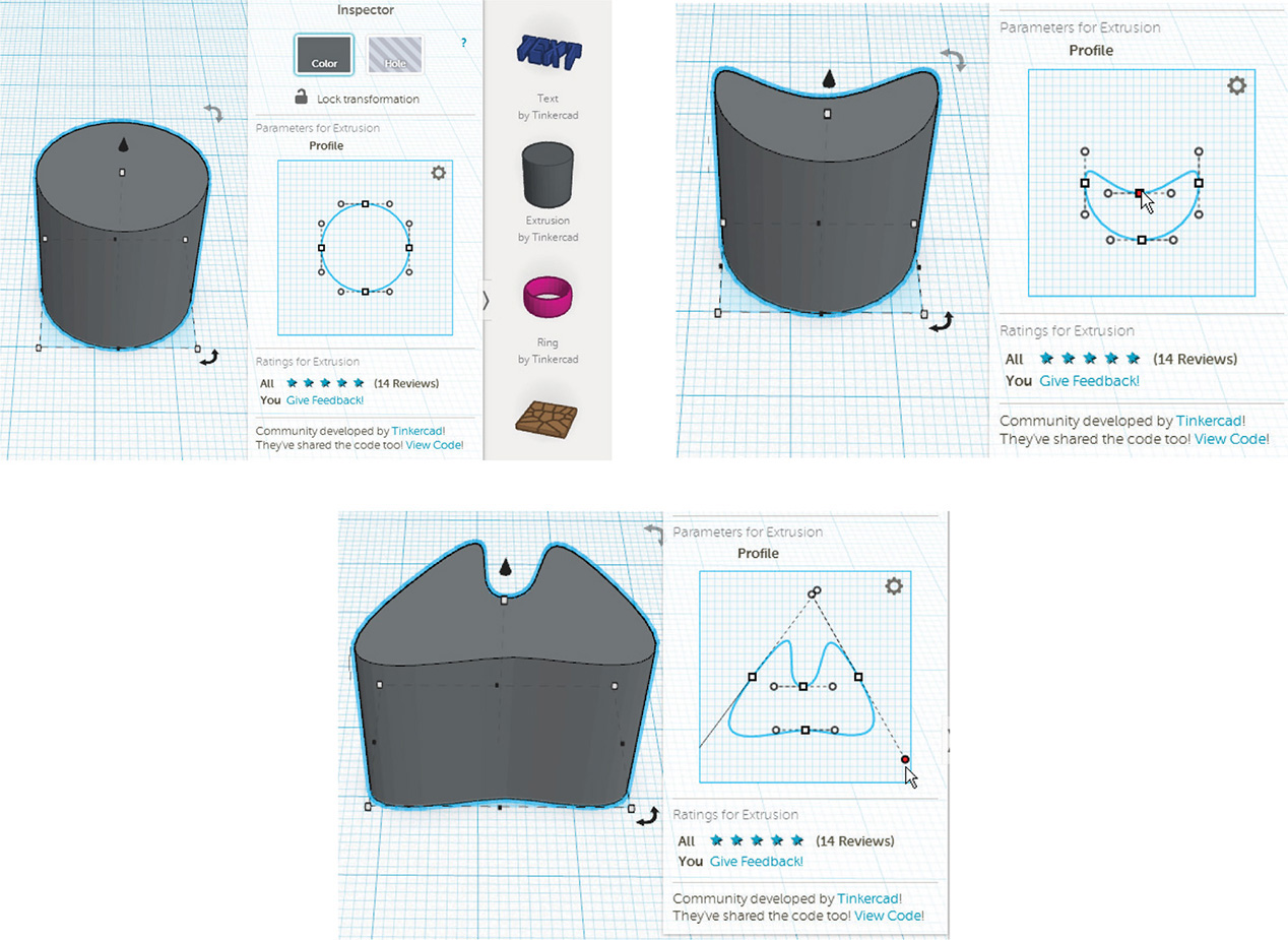
Figure 7-49 The Extrusion Generator can be made into just about any shape.
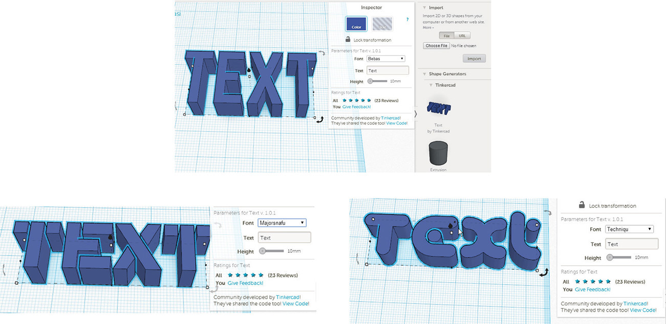
Figure 7-50 The Text Generator offers font choices.
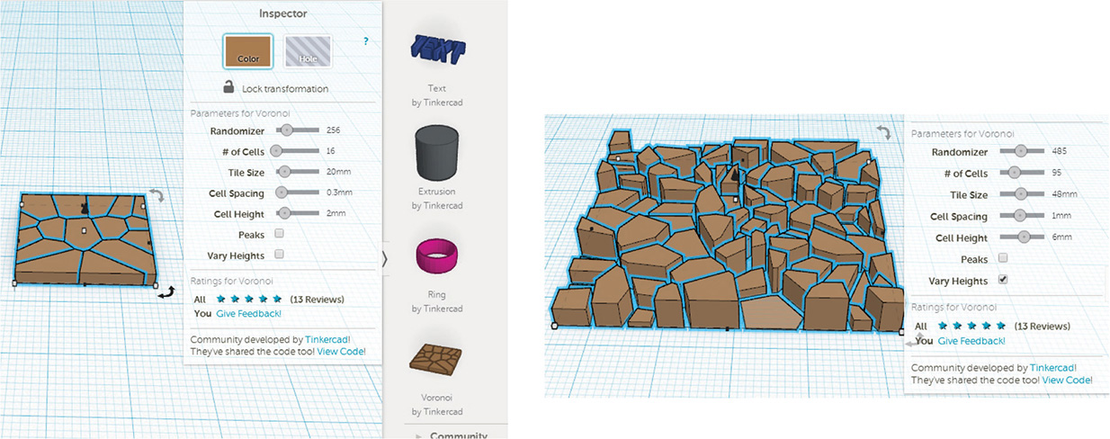
Figure 7-51 The Voronoi Generator creates organic shapes.
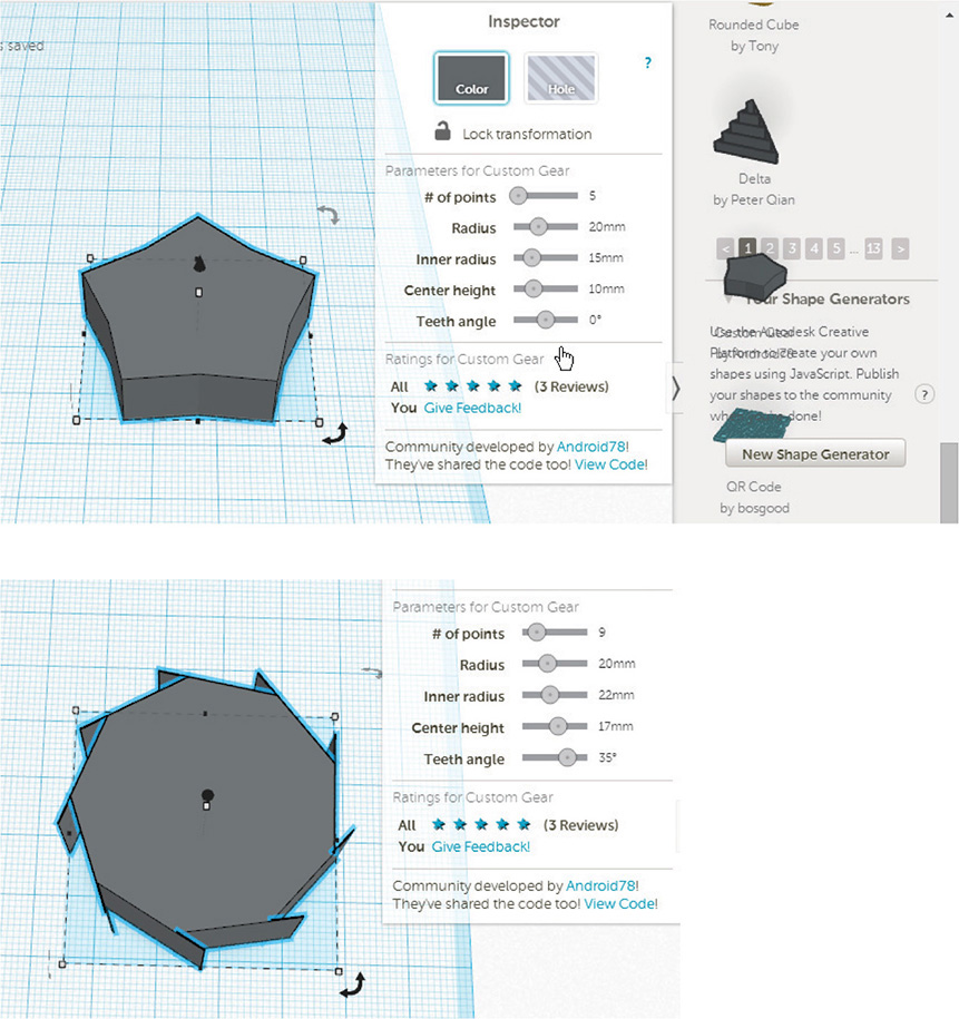
Figure 7-52 The Custom Gear Generator makes gears of all sorts.
Figure 7-53 shows a helix that’s in the community collection. I adjusted it with the control panel and made it taller by dragging the arrow manipulator. Then I dragged a cylinder out from the Geometric library, scaled it tall and thin, and placed it inside the helix for a perch that any cat would like to hang out on.
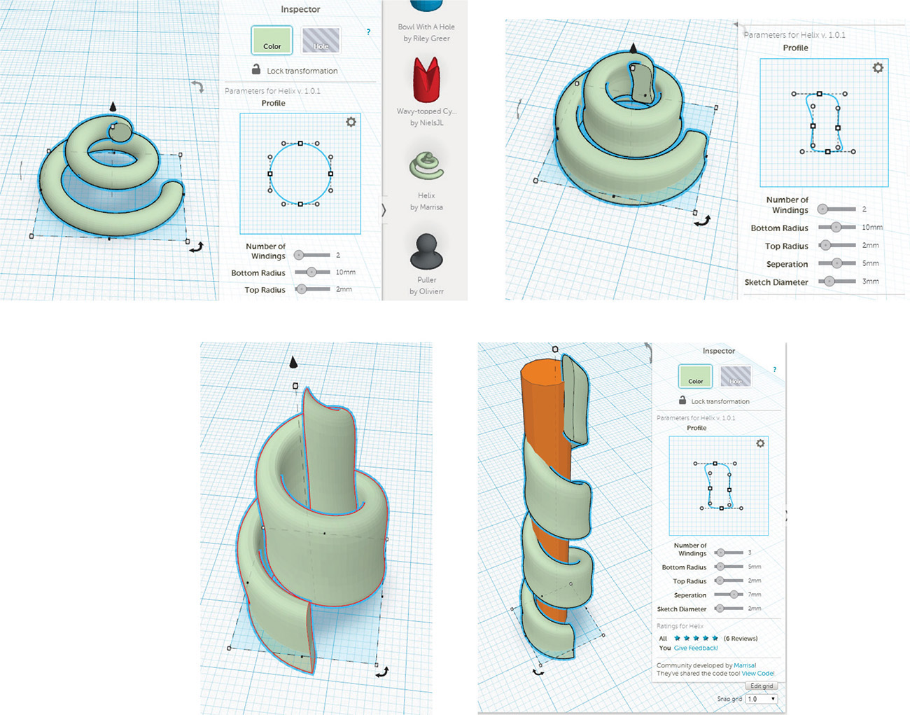
Figure 7-53 A cat perch made with a Shape Generator helix.
If you’re interested in making your own Shape Generators, a link with information is at the end of this chapter. Also, select Your Shape Generators | New Shape Generator and then click one of the shapes to see its code, which you are encouraged to edit (see Figure 7-54). Many Shape Generator programmers make their code accessible. Study it as another means of learning it.

Figure 7-54 The Your Shape Generators | New Shape Generator collection makes each shape’s code accessible for study and editing.
A creative use of parts, holes, and shape generators really extends what you can do with Tinkercad. For example, at https://tinkercad.com/things/la63cSw4tbV is a user-made Shape Generator called Easy Fillets that rounds off square corners (see Figure 7-55). Click the Tinker This button to make it your own. Make a square part with the Rectangle geometric shape, move an Easy Fillet to a corner, and adjust the radius if needed. Group the Easy Fillet and the part, click the workspace to exit, and the part now has a round corner (see Figure 7-56).

Figure 7-55 A user-made Shape Generator called Easy Fillets.

Figure 7-56 Using the Shape Generator to make a square corner round.
Summary
Tinkercad is a simple, powerful, web app designed especially for those with no solid modeling experience. Models, called “designs,” are made by pushing shapes together and using the hole, align, grouping, and mirroring tools on them. Shape Generators and the ability to import .stl files greatly expand this app’s capabilities. All Tinkercad files can be exported as .stl files, which enables them to be further developed in other programs.
Sites to Check Out
![]() Tinkercad help forum http://forum.123dapp.com/123d/products/123d_tinkercad
Tinkercad help forum http://forum.123dapp.com/123d/products/123d_tinkercad
![]() Tinkercad blog http://blog.tinkercad.com/
Tinkercad blog http://blog.tinkercad.com/
![]() Twitter handle @tinkercad
Twitter handle @tinkercad
![]() Keyboard shortcuts http://blog.tinkercad.com/keyboard-shortcuts/
Keyboard shortcuts http://blog.tinkercad.com/keyboard-shortcuts/
![]() Information about Creative Commons and its licenses www.creativecommons.org
Information about Creative Commons and its licenses www.creativecommons.org
![]() Information on Shape Generators http://blog.123dapp.com/2013/12/sketch-and-text
Information on Shape Generators http://blog.123dapp.com/2013/12/sketch-and-text
![]() Information on exporting Tinkercad files into Minecraft http://blog.tinkercad.com/?s=export
Information on exporting Tinkercad files into Minecraft http://blog.tinkercad.com/?s=export
![]() Shape Generator information for developers http://api.tinkercad.com/libraries/1vxKXGNaLtr/0/docs/index.html
Shape Generator information for developers http://api.tinkercad.com/libraries/1vxKXGNaLtr/0/docs/index.html