CHAPTER 8
Cut It! with 123D Make and the CNC Utility
SO YOU WANT TO MAKE a 3D item by assembling cut pieces of cardboard, acrylic, wood, or sheet metal? Then 123D Make is for you. Although Make files can be sent to a 3D printer, this app is primarily used to slice .stl and .obj models into manufacturable cutting patterns that can be read by computer-operated machines. It also generates a file that can be read by the Cricut Explore, an electronic device that cuts designs out of paper, card stock, poster board, vinyl, and fabric.
Cut patterns have diverse uses; for instance, they can be a craft kit, terrain model, piece of sculpture, or furniture prototype. Figure 8-1 shows examples from the 123D Gallery. The chairs are made from glued-together stacks, and the Snuffleupagus is made from folded panels; the bull’s stacked sheets include two dowels. Make even generates assembly instructions showing how the cut pieces go together.
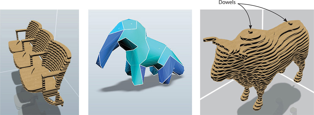
Figure 8-1 Examples of .stl files turned into sliced assemblies with 123D Make
Perhaps you just want to carve your ready-made pattern out of wood, and not by hand. Then the CNC Utility is for you. It turns a design into a file that a CNC (computer numeric controlled) machine can read. That’s a machine operated by a personal computer that holds the cutting tools as well as moves, cuts, drills, and shapes wood. It could be the same computer you did your drawings on.
In this chapter we’ll look at both apps, starting with Make. At www.123dapp.com/make you’ll find three platforms: iPhone/iPad, Web, and PC/Mac desktop. Download the desktop app because it has the most features.
Getting a Make-Importable File
First, you need a Make-importable file. 123D Make imports .stl and .obj files. They should be finished products because there are no tools for editing models in Make. In fact, if your .stl or .obj file won’t import into Make, it may be due to holes, manifold edges (edges shared by more than two polygons), or some other flaw that makes it nonprintable. In this case, import it into Meshmixer for analysis and repair (discussed in Chapter 9). Here’s how to get a Make-importable file from the different 123D apps (see Figure 8-2):
![]() 123D Design You can send a .123dx file directly from Design to Make. You can also select just a portion of the Design file and send it to Make through the glyph that appears when a model is selected. This enables different fabrication options on the model, such as stacked slices on one part and interlocked slices on another. Alternatively, export the .123dx file to an .stl file to your computer.
123D Design You can send a .123dx file directly from Design to Make. You can also select just a portion of the Design file and send it to Make through the glyph that appears when a model is selected. This enables different fabrication options on the model, such as stacked slices on one part and interlocked slices on another. Alternatively, export the .123dx file to an .stl file to your computer.
![]() 123D Catch The .3dp file is in your online 123D account. Click Models, select the specific model, and then click the Edit | Download button to download .stl and .obj files to your computer.
123D Catch The .3dp file is in your online 123D account. Click Models, select the specific model, and then click the Edit | Download button to download .stl and .obj files to your computer.
![]() 123D Meshmixer Export the .mix file to your computer as a binary (not ASCII) .stl file.
123D Meshmixer Export the .mix file to your computer as a binary (not ASCII) .stl file.
![]() Tinkercad Download the .stl file to your computer.
Tinkercad Download the .stl file to your computer.
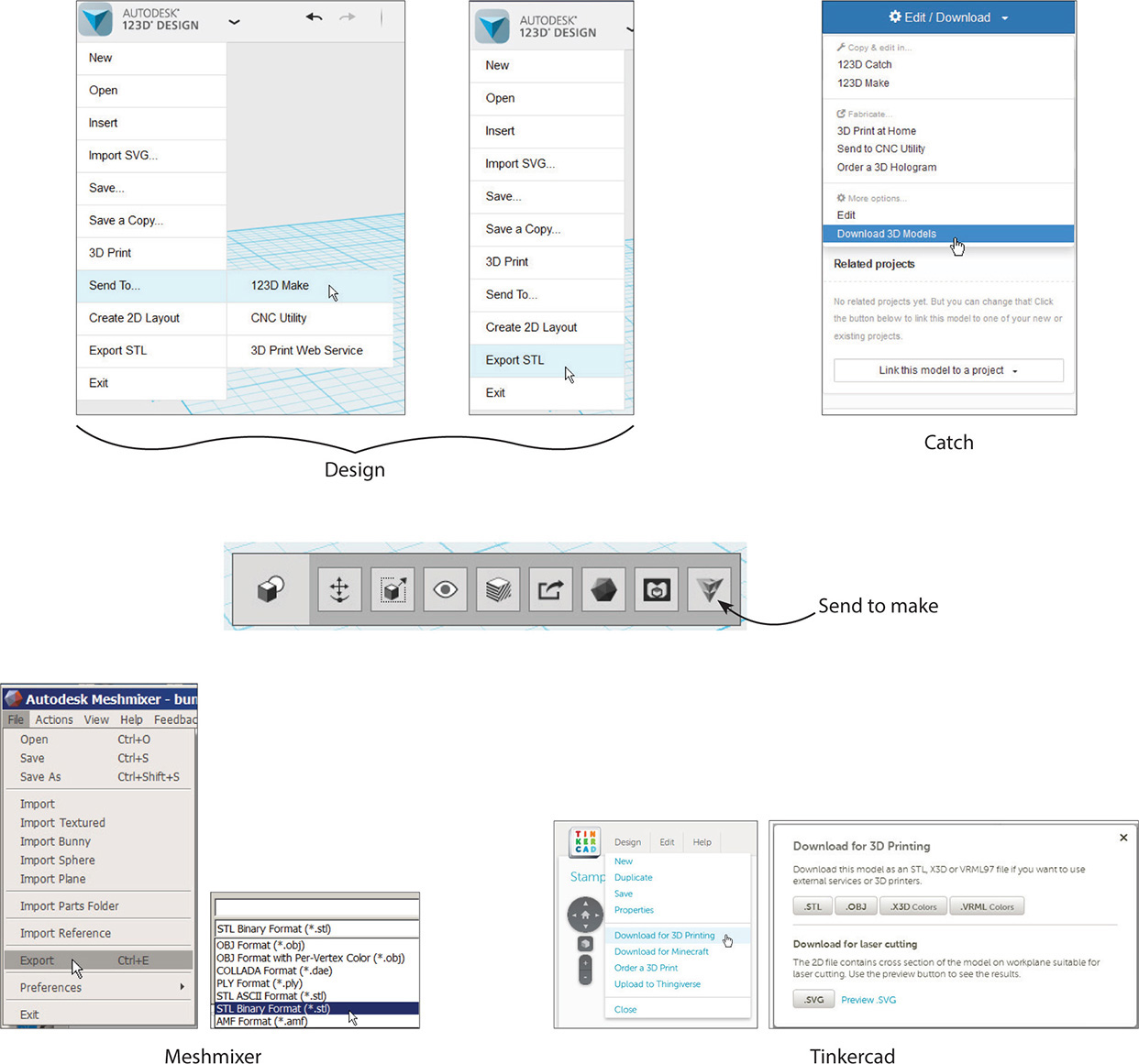
Figure 8-2 How to turn 123D app files into Make-importable files
The 123D Make Interface
Once you launch Make, you’ll see the interface shown in Figure 8-3. It consists of a workspace, menu bar at the top, and vertical panel on the left. The menu bar has a drop-down arrow that accesses a submenu (see Figure 8-4). It also has Undo and Redo arrows as well as links to your online account/resources (see Figure 8-5). There are also icons to rotate the model and see the changes made to it. Those are grayed out because we haven’t imported a model yet.
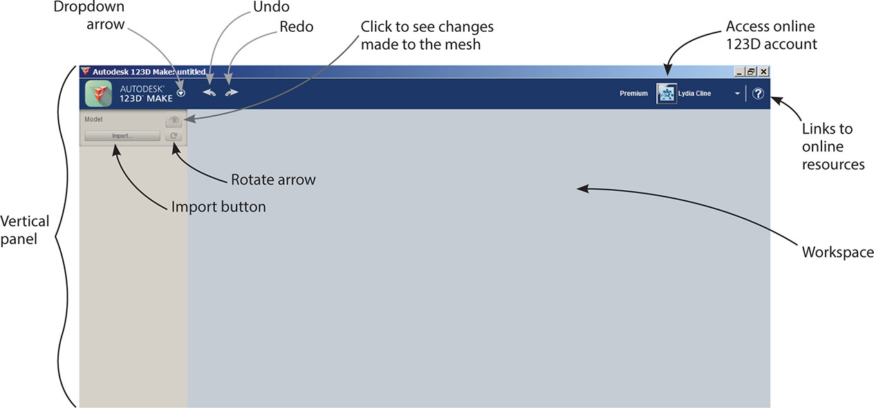
Figure 8-3 The Make interface

Figure 8-4 Click the drop-down arrow in the menu bar to see this submenu.
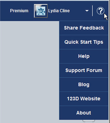
Figure 8-5 Links to your online account/resources are on the menu bar.
The menu bar’s submenu contains these functions:
![]() New This item closes the current file and makes the Import button appear.
New This item closes the current file and makes the Import button appear.
![]() Open Example Shapes This item brings up choices of premade files to experiment with.
Open Example Shapes This item brings up choices of premade files to experiment with.
![]() Open This item brings up a browser window where you can open a project from your computer, online 123D account, or the 123D Gallery (see Figure 8-6). You need to be logged in to access it.
Open This item brings up a browser window where you can open a project from your computer, online 123D account, or the 123D Gallery (see Figure 8-6). You need to be logged in to access it.
![]() Save Click here to save a .3dmk (Make) file to your computer or to your online 123D account.
Save Click here to save a .3dmk (Make) file to your computer or to your online 123D account.
![]() Save a Copy Click here to save a copy of the .3dmk file to your online 123D account. It will become the current file.
Save a Copy Click here to save a copy of the .3dmk file to your online 123D account. It will become the current file.
![]() Export Mesh This item turns the .3dmk file into an .stl or .obj file.
Export Mesh This item turns the .3dmk file into an .stl or .obj file.
![]() 3D Print This item sends the .3dmk file to Meshmixer for printing preparation.
3D Print This item sends the .3dmk file to Meshmixer for printing preparation.
![]() Exit This item closes the file and exits the app.
Exit This item closes the file and exits the app.

Figure 8-6 Click Open to navigate to a file on your computer, online account, or 123D Gallery.
Click the Import button on the vertical panel to bring up a navigation browser (see Figure 8-7). We’ll navigate to and import the glass head capture made in Chapter 5 (see Figure 8-8). If the model enters at an odd angle, as in the top graphic, it’s because the program it was imported from doesn’t share the same coordinate system as Make. Adjust it by clicking the rotate arrow in the vertical panel or by using navigation tools. To that end, note the ViewCube and navigation bar that now appear in the workspace (see Figure 8-9).

Figure 8-7 Click Import and browse to an .stl or .obj file.

Figure 8-8 An imported .stl file of a glass head. It imported at an odd angle and was straightened with navigation tools.

Figure 8-9 A ViewCube and navigation bar appear after a model is imported.
Navigate the Interface
You can move around the interface in one of three ways:
![]() By using the navigation bar The navigation bar contains tools for tumbling, panning, zooming, and framing the model. They are:
By using the navigation bar The navigation bar contains tools for tumbling, panning, zooming, and framing the model. They are:
• Tumble Click and drag to move the model at any angle around the workspace.
• Pan Click and drag to slide the model around the workspace.
• Zoom Click and drag the cursor up and down for a view that’s closer to or farther from the model.
• Look At Click to center the model and fill up the screen.
• Toggle Click to switch between perspective (3D) and orthographic (2D) views.
![]() By using the ViewCube The ViewCube shows the model’s orientation on the workspace. Click the ViewCube and drag to rotate it. The model will rotate along with the ViewCube. Click the View Cube’s sides to see the model orthographically (that is, as a 2D top, front, or side view). Hover the mouse over the ViewCube to make a house icon appear. Click that icon to return the model to a perspective view.
By using the ViewCube The ViewCube shows the model’s orientation on the workspace. Click the ViewCube and drag to rotate it. The model will rotate along with the ViewCube. Click the View Cube’s sides to see the model orthographically (that is, as a 2D top, front, or side view). Hover the mouse over the ViewCube to make a house icon appear. Click that icon to return the model to a perspective view.
![]() By using the mouse Right-click anywhere on the screen and drag the cursor to tumble the model (that is, move it at any angle around the workspace). Press down the scroll wheel to drag the cursor, which pans (slides) the model around the workspace. Roll the scroll wheel up and down to zoom in and out.
By using the mouse Right-click anywhere on the screen and drag the cursor to tumble the model (that is, move it at any angle around the workspace). Press down the scroll wheel to drag the cursor, which pans (slides) the model around the workspace. Roll the scroll wheel up and down to zoom in and out.
Options for settings also appear in the vertical panel after a model is imported. Note the button that says “head.stl.” Clicking it makes the file close and a browser for importing a new file appear.
Choose the Manufacturing Settings and Object Size
We need to select the sheet size the project will be cut from. Click the pencil button to access the Manufacturing Settings box shown in Figure 8-10, and scroll through the choices. If you’ll be using a laser-cutting service through 123dapp.com, choose preset P1, P2, or P3. To make a variation of a preset, click that preset to highlight it and then click the double-plus sign icon to duplicate it. Enter the new settings. To delete a preset, highlight it and click the minus sign icon.

Figure 8-10 Click the pencil button to access the Manufacturing Settings box. Then, choose a sheet dimensions preset or create your own.
This screen also has graphics at the bottom for adding your own presets, which is handy for nonstandard materials. Click the plus sign icon to add a new preset, then enter the units, slot offset, and length, width, and thickness of the material into the text fields.
Now select the model’s physical size. Choose its units and adjust the height, width, and length if needed. Clicking the Uniform Scale button scales the file in all directions. When it’s unchecked, you can scale the model differently along the three axes. Clicking the Original Size button reverts the file back to the size at import. Obviously, the larger the file is, the more slices that will be generated, and the more sheets you’ll need.
Construction Technique
Now the fun starts! At the bottom of the panel is the Construction Technique box. There you’ll find six types: Stacked Slices, Interlocked Slices, Curve, Radial Slices, Folded Panels, and 3D Slices.
Each technique has at least one option unique to it, but most options overlap between them. Click the drop-down arrow to select a technique (see Figure 8-11). The model will update to reflect it, with accompanying 2D graphics of slices laid out on sheets in the Cut Layer tab to the right. As you finesse the options, the slices automatically update. Be aware that slices and parts are not synonymous. A slice can consist of multiple parts.

Figure 8-11 Click the drop-down arrow in the Construction Technique box to see the choices.
Use Stacked Slices for the Make Process
Let’s go through the whole Make process, from choosing the technique to printing the file. We’ll use the Stacked Slices technique. Here are the steps to follow:
1. Click the Stacked Slices option technique. This makes cross-sectional slices for gluing and stacking on top of each other (see Figure 8-12). The Dowels option creates pegs that help align and hold the slices together, and it lets you choose their size, location, and shape (see Figure 8-13). Move a dowel by highlighting and dragging it; delete it by highlighting and pressing the DELETE key. Change the slice direction, as shown in Figure 8-14, by dragging the blue handle. The handle can only be dragged when it’s visible (dark blue), not hidden (muted) behind the model. Click the Model Issues button to see problems such as unconnected parts; they’ll show up in blue (see Figure 8-15).
Sometimes problems can only be fixed by changing the model somewhat. In that case, click the Modify Form icon. Three buttons will appear at the bottom of the screen: Hollow, Thicken, and Shrinkwrap (see Figure 8-16). Hollow shells out the model, reducing the amount of material needed to build it. Thicken widens cutouts that are too thin to fabricate. Shrinkwrap approximates and smoothes details that are too fine to cut out. It also closes holes, which is particularly useful on models made with 123D Catch. Select one, adjust its slider, and click Done.
Be aware that Shrinkwrap affects the whole model, not just a problem slice. Therefore, the end product may not look exactly like the model. Additionally, you should know the machine’s limitations; for instance, a router can’t make square corners. Appropriate clearances are needed, which is the space for parts to connect.
2. Click the Assembly Steps icon and choose the material (see Figure 8-17a). Drag the mouse along the slider at the bottom of the screen to watch an animation putting the parts together. To view an assembly sheet, click its thumbnail in the Assembly Reference panel (see Figure 8-17b). Move the sheet by clicking and dragging; scroll the mouse wheel to zoom in on a part; click the X in the upper-right corner to return to the model.
Study the graphics in the Cut Layout tab. They show how many sheets of material are needed, how many slices and parts there are, and where problems lie. Hyphenated labels, such as Z-3-2, describe the part’s axis (Z), the slice number (3), and part number (2). Blue outlines are the model’s outside edge; green outlines are cuts inside the model for hollows; yellow outlines are scored guides for placing parts during assembly.
The parts are arranged to use as much of each sheet as possible, and all are oriented the same direction. Currently, there is no other way to arrange them. If you want to change the arrangement—perhaps the wood grain faces the wrong direction—import the file into another vector program such as Inkscape or Illustrator and change it there.
3. Export the file by clicking the Get Plans icon, choosing the format (.eps, .pdf, or .dxf) and units, and clicking Export (see Figure 8-18). The file will be exported into a format ready to import into a CNC machine or Cricut. The .eps option creates a ZIP folder with separate files for each sheet. This option, as well as the .dfx option, puts text on one layer and profiles on another, which is useful when laser cutting. The .pdf option creates one file that puts all the slices on separate pages (see Figure 8-19). Its advantage is that it can be viewed with the ubiquitous Adobe Reader, whereas you may not have an program that can read .eps files.

Figure 8-12 The Stacked Slices option turns the form into cross-sectional slices.
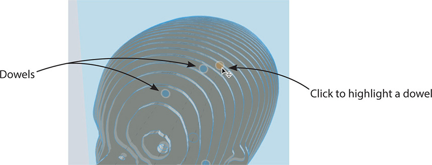
Figure 8-13 Adjust dowel locations by dragging them.
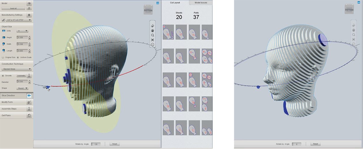
Figure 8-14 Change the slice direction by dragging the blue handle.

Figure 8-15 Click the Model Issues button to see problems. Here, the blue part is unconnected to the rest of the slice.

Figure 8-16 The Modify Form options may be able to fix problems inherent in the model.
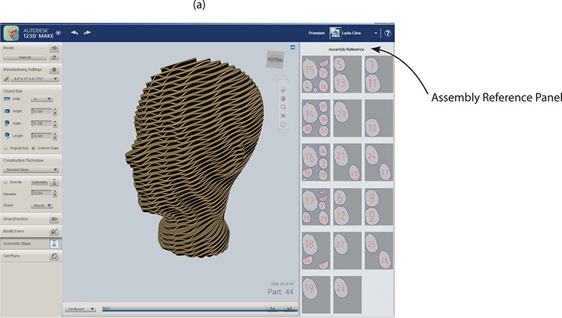

Figure 8-17 (a) Click the Assembly Steps icon to choose the material. (b) See an animation of how to put the parts together.
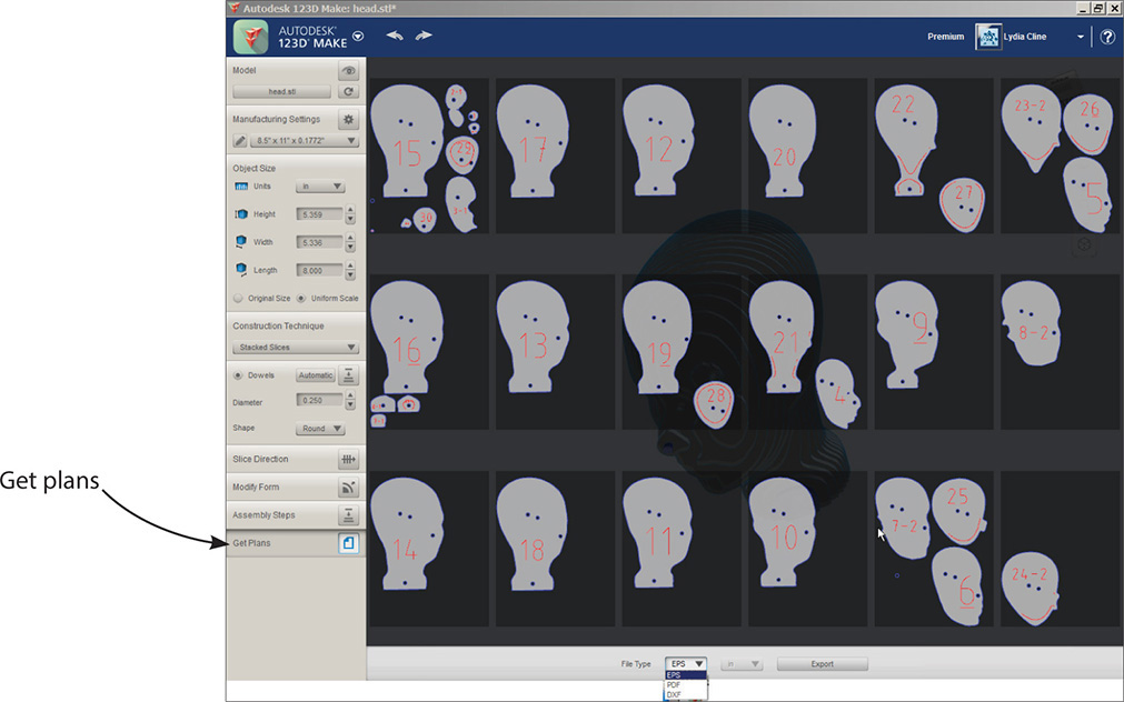
Figure 8-18 Click the Get Plans icon, choose a file format, and export it.
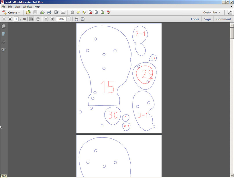
Figure 8-19 An exported .pdf file of the slices
Interlocked Slices
This technique slices the model into two stacks of slotted parts that lock together in a grid. It uses less material than the Stacked Slices technique. Problem slices show up in red (see Figure 8-20) and may be fixed by adjusting the options shown in Figure 8-21. Those options include letting you adjust the slice distribution, notches, and relief. You can distribute the slices by count, distance, or a custom setting. The 1st Axis field sets the number of slices in each direction, and the 2nd Axis fields set the distance between slices. Increase the numbers to give the model a more defined form or decrease them to use less material. Click the horizontal bars to bring up graphics that duplicate, delete, and evenly distribute the slices. Click any slice and drag it to change its position. Click the Evenly Distribute button after moving individual slices to evenly space them. To add a slice, highlight an existing one and click. A duplicate will appear next to it that follows the model’s contours. To remove a slice, highlight it and click Delete.

Figure 8-20 The Interlocked Slices technique. A problem slice is indicated in red and may be fixed by adding slices via the 1st Axis field.

Figure 8-21 Options for the Interlocked technique. Click the bars to bring up the Duplicate, Delete, and Evenly Distribute buttons.
Large parts can twist, making assembly difficult or impossible. Make’s default square-cornered slots may also cause assembly problems, depending on the design. Use the Notch Factor field to flair the slot by a specific amount relative to its width; use Notch Angle to set the angle relative to the slot’s direction (see Figure 8-22). A 45° angle often works. Ensure that notches of any time are wide enough to be cut out.
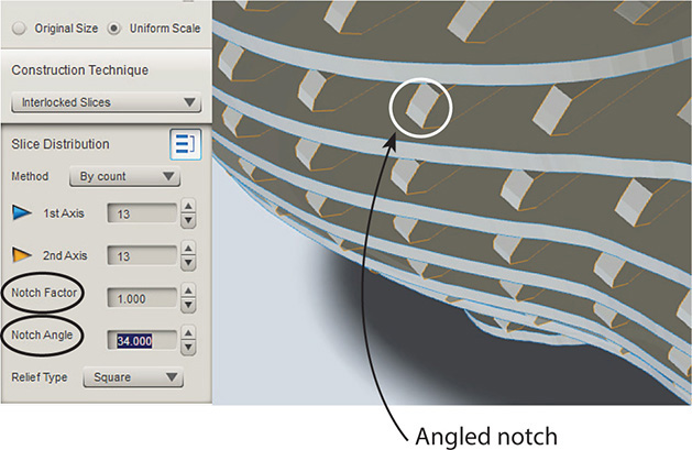
Figure 8-22 Notches are square by default but can be angled.
The term relief refers to the notch shape. The default relief type is square, but you can choose a relief type of horizontal, vertical, or dog bone, which is a shape with no inside rounded corners. You can further edit the relief by specifying the tool diameter. Go back to the Manufacturing Settings, make a new preset, and enter a number in the Tool Diameter field. Dog bones can’t be generated when the Tool Diameter is set to zero.
Curve
This technique cuts slices perpendicular to a curve (see Figure 8-23). All the curves are on one plane. It works best on flowing, organic shapes, such as animals. Options are similar to those of the Interlocked Slices technique. Additionally, you can bend the curve.
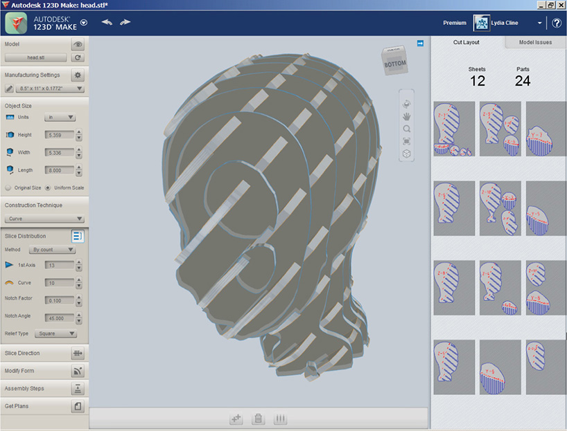
Figure 8-23 The Curve technique cuts slices perpendicular to a curve.
Radial Slices
This technique creates radiating slices from a central point. It’s best used on round, symmetrical objects. As you can see from its effect in Figure 8-24, not all designs are suited for all techniques. Here, the default generation (top) returned multiple problem slices. Adjusting the count, 1st axis, and slice direction fixed them (bottom left), but turning the model revealed a new, unconnected part (bottom right).

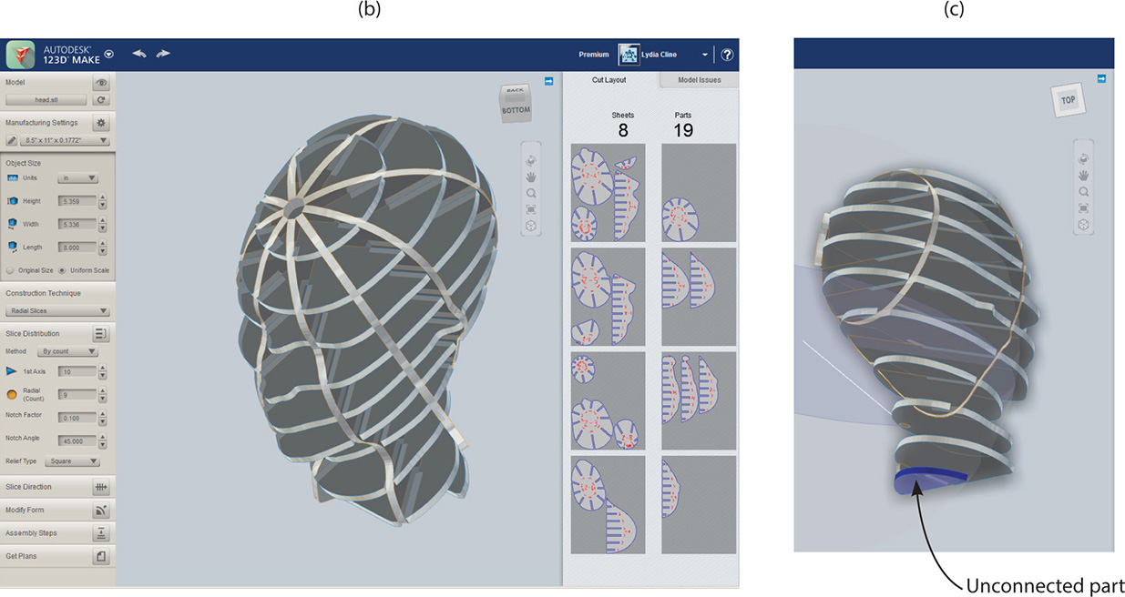
Figure 8-24 Slices in the Radial Slices technique emanate from a central point. This model displays multiple problem areas.
Folded Panels
This technique turns the model into 2D segments, or panels, of triangular meshes that are folded multiple times. Paper, cardboard, and sheet metal can be used with this technique.
Figure 8-25 (top) shows the default generated head. It has a lot of problem areas and a message that the parts are too large for the sheets. Clicking the Split Panels option turns every face into a panel, which fixes this but generates hundreds of parts. You can lower the vertex and face count to simplify the model (a process called “decimation”) to make assembly easier. Of course, this simplifies the model, too, as seen in the bottom graphic.. If you want to use the decimated model but preserve a copy of the file with its mesh intact, export it through the Export Mesh option in the menu bar (see Figure 8-26).

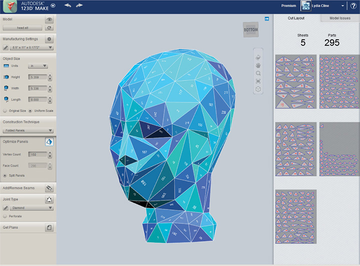
Figure 8-25 The top graphic shows multiple problem areas. The bottom graphic shows the model with split panels and lower vertex and face counts, which fixes the problems.

Figure 8-26 The menu bar’s Export Mesh option preserves the mesh.
Click the Add/Remove Seams icon and then click a panel edge to add fold lines that divide large panels into smaller ones or remove fold lines to combine small panels into bigger ones (see Figure 8-27). You can also turn fold lines into perforation lines. The perforations will be the thickness of the chosen material. Split Panels will deselect when you do this; click it again when finished if your model becomes covered with problem areas.
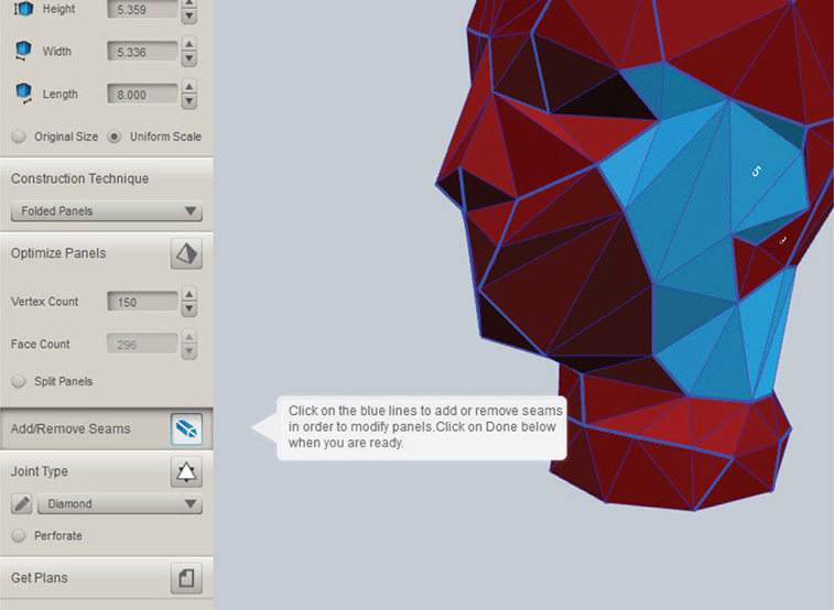
Figure 8-27 Click the Add/Remove Seams icon to make bigger or smaller panels.
Joints for Folded Panels Joints are tabs (which Make calls “ticks”) that connect the panels. There are 10 types, each shaped differently. All have finessing options (see Figure 8-28). If a model has lots of problem areas, changing the joint type often helps.
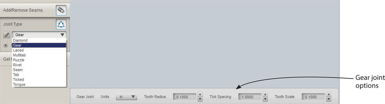
Figure 8-28 There are 10 joint types; the Gear joint and its options are displayed here.
Joint types are illustrated in Figure 8-29 and detailed in the following list:
1. Diamond Fold and glue/weld the triangular tabs.
2. Gear Fold and glue/weld the rectangular tabs (cut the dark area or areas out).
3. Laced Entwine the sheets together.
4. Multi-tab Fix the tabs together.
5. Puzzle Fit pieces together.
6. Rivet Pin tabs to one another.
7. Seam Sew tabs together (like a sewing pattern).
8. Tab Insert tabs into slots.
9. Ticked Connect tabs along the seams.
10. Tongue Insert a tab into slots.
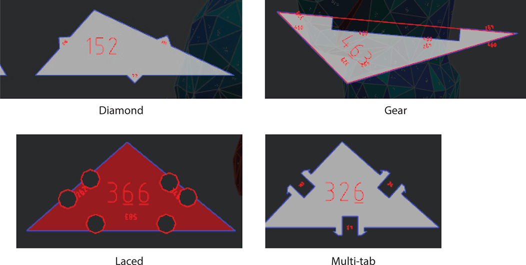
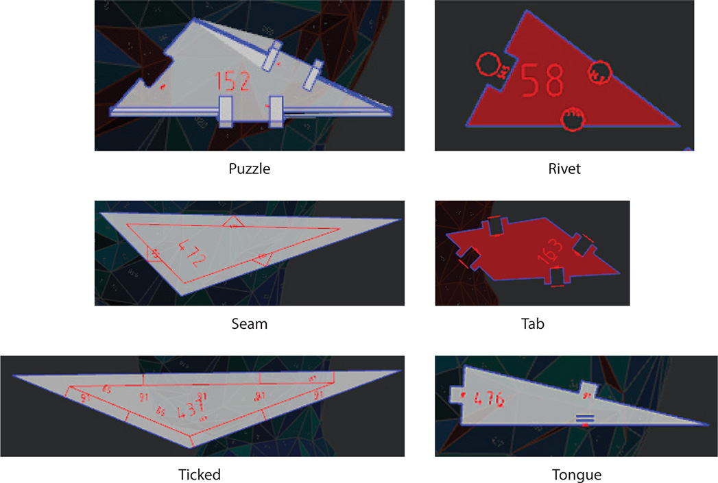
Figure 8-29 Folded panels have 10 joint options.
3D Slices
This technique slices the model. However, unlike Stacked Slices which merely step to create a form, 3D slices actually follow the form. That is, slices are made along all the x, y, and z axes (all three of the model’s physical dimensions). See Figure 8-30.

Figure 8-30 The 3D technique makes slices that follow the model’s form.
Save and Export the Model
You can save your work on your computer or to your online 123D account. When saving it online, as shown in Figure 8-31, you’ll be asked to describe it. You also choose between keeping it private and making it public, which displays it in the 123D Gallery. You can always edit these choices later. You can also export the model to your desktop as an .stl or .obj file (refer back to Figure 8-26).

Figure 8-31 Click the drop-down arrow on the menu bar to save the file. Saving to My Projects brings up a dialog box asking for more information.
Send the Model to a Service Bureau
At the www.123dapp.com site, click 3D Printing and then More Making Options (see Figure 8-32). Clicking Ponoko’s icon takes you to their site. Click Make at the top, click Make again, and then click Get Making (see Figure 8-33). After entering the project’s details, you’ll be quoted a price. The site has a tutorial video and a lot of information about their services. Know that the parts and slices will be mailed to you unassembled.
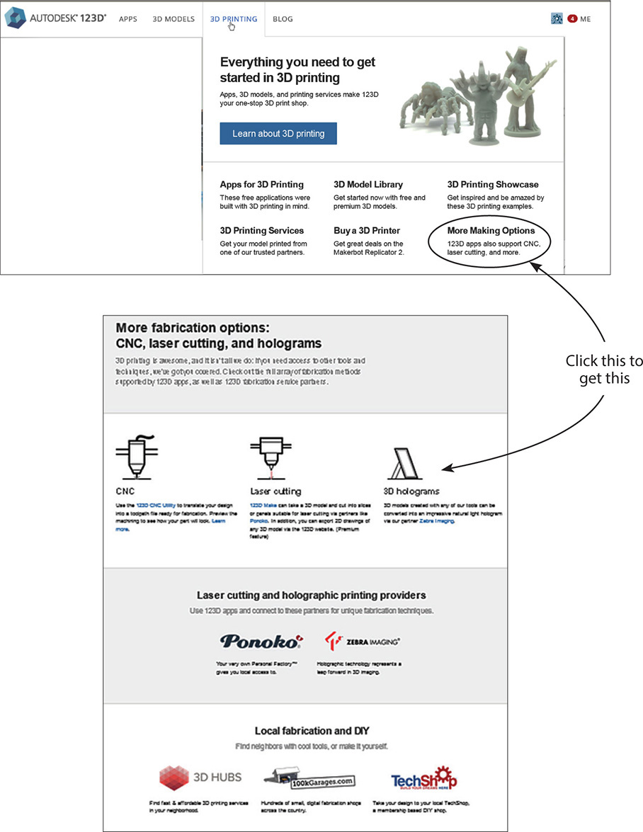
Figure 8-32 Service bureau options
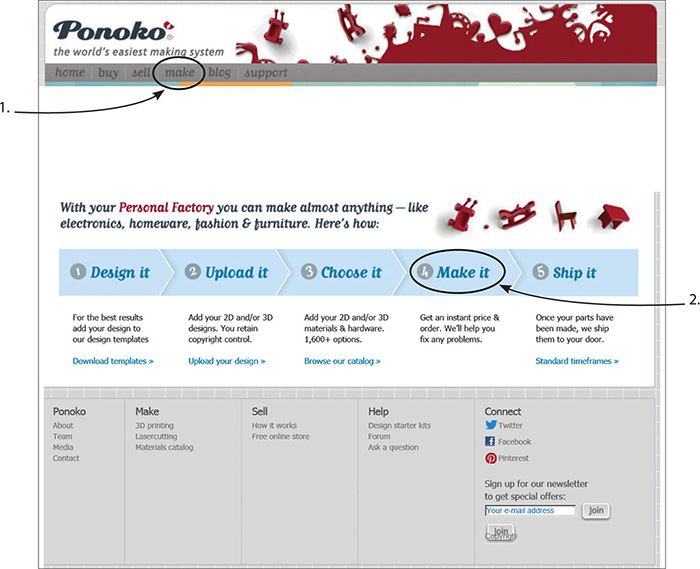
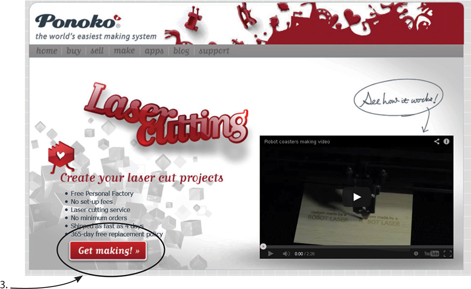
Figure 8-33 The order process at Ponoko
The CNC Utility
The CNC Utility is a web-based app for creating files that drive a CNC router. This is a tool that cuts sheets of wood, plastic, wax, cardboard, and foam (see Figure 8-34). The end result is a file of G-code, a language that computerized tools understand. G-code tells the tool where to move, how fast, and what path to take. You can then send this file to your personal router if you have one, or to an online service bureau or local hackerspace if you don’t.
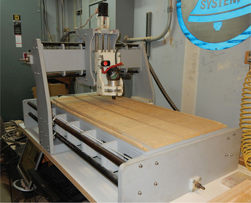
Figure 8-34 A CNC router is a tool that cuts sheets of wood, plastic, wax and foam. This router is in Hammerspace, a makerspace in Kansas City, MO.
There are built-in settings for the whole ShopBot line, a company whose CNC lathes and routers are standard equipment in woodworking shops. However, all CNC routers are supported, so you can make a setting for a different router.
Launching the CNC Utility
The CNC Utility can be launched from inside 123D Design (see Figure 8-35) or opened directly to import an .stl, .obj, .svg, or .eps file. Point the Chrome browser to http://apps.123dapp.com/cnc/ and click Start a CNC Project (see Figure 8-36). A browser will appear with which to navigate to a file in your online account, on your computer desktop, in the 123D Gallery, or to a premade example to play with. We’re going to import an .stl file of the “Be Happy” stamp that was made in Chapter 7 and stored on the computer desktop.

Figure 8-35 The CNC Utility can be launched from inside 123D Design.

Figure 8-36 At http://apps.123dapp.com/cnc/, click Start a CNC Project and then navigate to your file.
After the file is imported, a dialog box appears asking you to name and describe it (see Figure 8-37a). You have the option of keeping it private or making it public. It will then save to your online account. To return to it later, open the CNC Utility, navigate to your online account, click the My Projects tab (see Figure 8-37b), highlight the project’s thumbnail, and click Open Selected Project.

Figure 8-37 (a) The project must be named and saved before it can be worked on. (b) To return to the project later, navigate to your online 123D account, click the My Projects tab, and select its thumbnail.
The CNC Utility Interface
Once the project is saved, the workspace in Figure 8-38 appears.

Figure 8-38 The CNC Utility interface
The interface contains a workspace on which the project is edited, a menu bar, graphics for accessing your account and online resources, a ViewCube, a navigation bar, a graphic for choosing units, and a stock (material) ribbon. They are:
![]() Workspace This is a gridded surface on which the project is edited. The model appears on a default sheet of material.
Workspace This is a gridded surface on which the project is edited. The model appears on a default sheet of material.
![]() Menu bar The menu bar is shown in Figure 8-39. Here, you can access the following functions:
Menu bar The menu bar is shown in Figure 8-39. Here, you can access the following functions:
• Horizontal bars Click this icon for a submenu with the Open, Save, Save a Copy, Export Toolpath Files, Project Info, and Share Project functions (see Figure 8-40).
• Save Saves the project to your online account.
• Snap to Top Snaps the model to the top of the stock.
• Snap to Bottom Snaps the model to the bottom of the stock.
• Scale to Fit Scales the model uniformly to fit the stock.
• Stretch to Fit Stretches the model along one axis to fit the stock.
• Reset the Model Undoes all actions at once (there is no step-by-step undo function).
• Switch Active Plane Toggles between the bottom plane and the current plane.
• Precise Move Selects one or more objects to move.
• Precise Scale Selects one or more objects to scale.
• Precise Rotate Selects one or more objects to rotate.
![]() Graphics for accessing your account and resources These graphics provide links to your online account and sources of information and help (see Figure 8-41).
Graphics for accessing your account and resources These graphics provide links to your online account and sources of information and help (see Figure 8-41).
![]() ViewCube Click and drag the ViewCube to change its position. The model will change along with it. Click a side, such as Top or Bottom, to view the model orthographically (2D view).
ViewCube Click and drag the ViewCube to change its position. The model will change along with it. Click a side, such as Top or Bottom, to view the model orthographically (2D view).
![]() Navigation bar The navigation bar contains icons for moving around the workspace (see Figure 8-42).
Navigation bar The navigation bar contains icons for moving around the workspace (see Figure 8-42).
![]() Orbit Click and drag the mouse (hold down the left button) to move around the model at any height and angle. Alternatively, orbit by holding down the right mouse button and dragging.
Orbit Click and drag the mouse (hold down the left button) to move around the model at any height and angle. Alternatively, orbit by holding down the right mouse button and dragging.
![]() Pan Click and drag the mouse to slide the model around the screen. Alternatively, pan by holding the mouse’s scroll wheel down and dragging.
Pan Click and drag the mouse to slide the model around the screen. Alternatively, pan by holding the mouse’s scroll wheel down and dragging.
![]() Magnifying glass Click this to zoom the model around the cursor location.
Magnifying glass Click this to zoom the model around the cursor location.
![]() Square Click this to fill the screen with the model.
Square Click this to fill the screen with the model.
![]() Eye Toggle between perspective (3D) and orthographic (2D) views.
Eye Toggle between perspective (3D) and orthographic (2D) views.
![]() Unit Click this to choose inches (in), centimeters (cm), or millimeters (mm), as shown in Figure 8-43.
Unit Click this to choose inches (in), centimeters (cm), or millimeters (mm), as shown in Figure 8-43.
![]() Stock ribbon This horizontal bar, shown in Figure 8-44, has parts for choosing the machine and stock, altering the model size, and adding tabs (pieces that hold the model to the stock while it’s being carved). The Tool and Preview icons bring up sub-ribbons. Click the wrench/screwdriver icon to return to the main ribbon. Click on this to choose the project’s units.
Stock ribbon This horizontal bar, shown in Figure 8-44, has parts for choosing the machine and stock, altering the model size, and adding tabs (pieces that hold the model to the stock while it’s being carved). The Tool and Preview icons bring up sub-ribbons. Click the wrench/screwdriver icon to return to the main ribbon. Click on this to choose the project’s units.
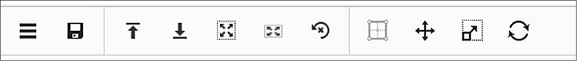
Figure 8-39 The menu bar
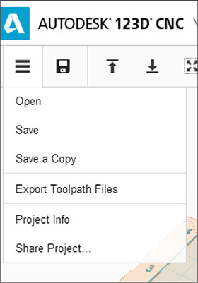
Figure 8-40 Click on the horizontal bars to access a submenu of utility functions.
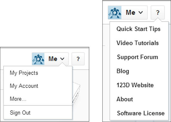
Figure 8-41 Click “Me” to access your 123D. Click “?” for links to video tutorials, the support forum, blogs, and other resources.
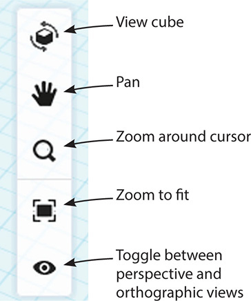
Figure 8-42 The navigation bar has icons for moving around the workspace.

Figure 8-43 Select the file’s units.

Figure 8-44 The stock ribbon contains sections for choosing options as well as icons that access sub-ribbons.
Steps for Creating a G-Code File
Here are the steps for setting up the model to create a G-code file:
1. Choose the machine, as shown in Figure 8-45. For this example, we’ll use the ShopBot Desktop, a tabletop router.
2. Choose the stock material and its dimensions, as shown in Figure 8-46. In the Stock field, click the drop-down menu and select Add. For this example, I chose plastic for the sheet material. The stamp is 4” long by 3/4” wide by 1/2” high, so I typed dimensions a bit larger than those and then clicked Save. Now when I click the Stock section, as shown in Figure 8-47, the pop-up box reflects the new material and size, as does the stock model in the workplane.
3. Tweak the model’s size if needed and adjust its position on the stock. To do this, click Model. This brings up text fields and arrowhead manipulators (see the left graphic on Figure 8-48). Change the size by dragging the manipulators or typing the new size. The model will scale proportionately along all axes unless you click the chain link; then you can scale along one axis. It’s best to finalize the model’s size in the app it was created in because if you need to reset it, you’ll lose any sizing done in this app.
Move the model on the stock by dragging the black arrows or typing a displacement distance in the Move field (the field will appear after you drag the model a bit with a manipulator). Place the model so that there’s some clearance between it and the stock’s edges and then snap it to the bottom of the stock (see the left graphic on Figure 8-48). Click anywhere on the workspace to exit.
4. Add tabs, as shown in Figure 8-49. These should extend from the edges of the stock to the edges of the model. Click the Tabs plus sign and move the mouse (don’t drag it) to the desired location. Click the mouse to place the tab. Click another tab onto the model and press the TAB key to rotate it 90°, as needed. Adjust the tab’s size by typing in the dialog box that appears when the tab is clicked into place. Highlight it in the dialog box and type in new dimensions if needed, or highlight it in the dialog box and click the trash can to delete the tab. Put tabs on all sides. Size-wise, they should have a shorter height than the model.
5. Set up the toolpaths (see Figure 8-50). Click the tool icon to make a sub-ribbon appear. Click the gear in each sub-ribbon part to access a menu, and click the drop-down arrows in the menus’ text fields to access (Figure 8-51b). A solid knowledge of CNC milling is needed to make the best choices.
6. Preview the toolpath by clicking the gray eye in each of the sub-ribbon’s parts. This generates a visible toolpath (see Figure 8-52). Black lines mean the tool is actively routing (cutting). Red lines mean the tool is traveling (stepping over). Study the toolpaths for errors before machining. Examples are black lines crossing through parts of the stock you don’t want cut and red lines moving through unrouted stock, which will damage the bit.
7. View the toolpath animation. This can help you find errors. Click the Preview graphic on the stock ribbon to get the sub-ribbon in the top graphic of Figure 8-53, and then click Preview Settings to bring up a dialog box. Click the options you want to see, and they’ll appear (bottom graphic).
Click the play button to see a simulation of the physical model getting cut (see Figure 8-54). Click the fast-forward button once to skip to the end of the rough pass, twice to skip to the end of the finish pass, and three times to skip to the end of the cut-out pass. Know that the physical model will be smoother than it looks in the animation.
8. From the menu bar, choose Export Toolpath Files (see Figure 8-55). Because multiple files are generated, make a folder on the local desktop for them. The whole folder needs to be copied to the PC that controls the CNC machine. This is typically done via a USB stick (thumb drive). There will be duplicates in the toolpath files. This is because .g is a generic G-code file and .sbp is a ShopBot G-code file. When setting up the CNC machine, check out the Readme.txt file for information that will need to be programmed into it (see Figure 8-56).
9. If you don’t have your own CNC machine, send the files to an online service bureau via the 123D website (see the process for this in the 123D Make discussion earlier in this chapter), or take them to a local hackerspace. Some are listed at the end of this chapter.
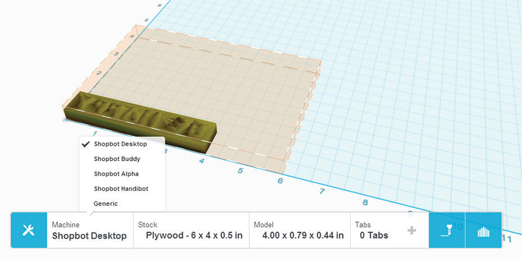
Figure 8-45 Choose the machine.

Figure 8-46 Steps for choosing the stock material and its dimensions

Figure 8-47 Click the Stock section to see the new entry. The stock model in the workplane reflects the new size.

Figure 8-48 Click the Model field to change the size, if needed, and its location on the stock. Then snap it to the bottom of the stock.

Figure 8-49 Adding tabs to the model.

Figure 8-50 The Toolpath sub-ribbon

Figure 8-51 Click the gear in the Rough Pass, Finishing Pass, and Cut Out Pass sections to access menu choices specific to each one. Then click the dropdown arrows in the Tools text field for submenu choices.

Figure 8-52 Click the gray eye in each part to generate toolpaths. Black (cutting) lines are on the letters; red (stepping) lines are above the letters. Here, toolpaths for each pass are shown.

Figure 8-53 Click the Preview graphic on the stock ribbon, click Preview Settings, and then select the options wanted. The bottom graphic shows the options checked and the picture generated.
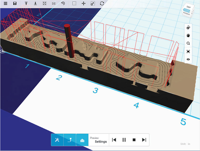
Figure 8-54 Click the play button to see a simulation of the physical model being cut.

Figure 8-55 Choose Export Toolpath Files to generate g-code.

Figure 8-56 The Readme.txt file contains information needed for programming the CNC machine.
Download an STL File of Your CNC Project
To get an .stl file of your CNC project, go to your online 123D account (see Figure 8-57). Click Models, click the appropriate thumbnail, and then click the Edit/Download button. Clicking the gear icon in the thumbnail view accesses a fabrication option (see Figure 8-58).
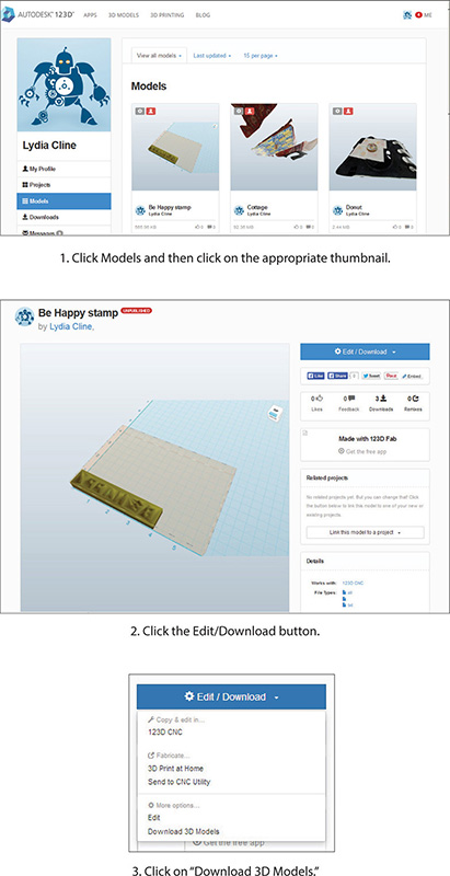
Figure 8-57 Downloading an .stl file from the online 123D account.

Figure 8-58 Click on the thumbnail’s gear to access an online fabrication option.
Summary
123D Make and the CNC Utility are powerful apps for projects made with cutting machines. You use Make to carve a model into parts for fabrication, whereas the CNC Utility generates files that a machine can read. The files can then be made locally or sent online to a third-party service bureau that can produce them for a fee.
Sites to Check Out
![]() FabLab, a community hackerspace www.fabfoundation.org/fab-labs/
FabLab, a community hackerspace www.fabfoundation.org/fab-labs/
![]() TechShop, a membership-based DIY studio with making tools http://techshop.ws/
TechShop, a membership-based DIY studio with making tools http://techshop.ws/
![]() GE’s traveling garage website www.ge.com/garages
GE’s traveling garage website www.ge.com/garages
![]() Service that matches people how have files with people how have equipment www.100kgarages.com
Service that matches people how have files with people how have equipment www.100kgarages.com
![]() Large custom manufacturing marketplace www.mfg.com
Large custom manufacturing marketplace www.mfg.com
![]() ShopBot tools website, where you can learn about their product line www.shopbottools.com
ShopBot tools website, where you can learn about their product line www.shopbottools.com
![]() Tormach tools website, where you can learn about their product line www.tormach.com
Tormach tools website, where you can learn about their product line www.tormach.com
![]() Cricut website, where you can learn about their product line and find lots of project ideas http://us.cricut.com
Cricut website, where you can learn about their product line and find lots of project ideas http://us.cricut.com
![]() Hackerspaces, a community-operated DIY studio with making tools http://hackerspaces.org
Hackerspaces, a community-operated DIY studio with making tools http://hackerspaces.org
![]() Make a piggy coffee table with a CNC router www.instructables.com/id/Piggy-Coffee-Table-CNC-Router/
Make a piggy coffee table with a CNC router www.instructables.com/id/Piggy-Coffee-Table-CNC-Router/
![]() Blog entry on Cricut projects http://blog.123dapp.com/2014/06/123d-make-3d-diy-projects-made-with-cricut
Blog entry on Cricut projects http://blog.123dapp.com/2014/06/123d-make-3d-diy-projects-made-with-cricut
![]() Learn more about CNC http://en.wikipedia.org/wiki/Numerical_control
Learn more about CNC http://en.wikipedia.org/wiki/Numerical_control
![]() Forum for ShopBot operators www.talkshopbot.com/forum/index.php
Forum for ShopBot operators www.talkshopbot.com/forum/index.php